True RESIDENTIAL User manual

TR-36RBF INSTALL GUIDE
07/28/2021TEC_TM_151 | REV. A | EN
36 INCH BUILT-IN BOTTOM FREEZER
INSTALL GUIDE AND USER'S MANUAL
TRUE RESIDENTIAL®
PRESERVE THE MOMENT®

TEC_TM_151 | REV. A | EN07/28/2021
TRUE RESIDENTIAL®
To ensure no part of the installation process has been overlooked, complete the checklist below.
Have all packaging materials been removed?
Are the anti-tip brackets securely installed and properly engaging the unit?
Has the unit been properly leveled? Do all leveling legs touch the floor?
Is the kickplate Installed?
Is the doorstop being installed (if needed)?
Does the customer understand the unit’s operation?
Has the customer been given the key and literature package?
Have all stainless steel surfaces been inspected for imperfections?*
Is the unit operating correctly? If not, is the unit plugged in? Is the control turned on?
*To be completed by either an installer with the customer or an authorized True dealer upon completion
of installation. Stainless steel doors, handles, and shelves are covered by a limited 30-day warranty for
cosmetic defects.
INSTALLATION CHECKLIST
NOTE: AS WE STRIVE FOR CONTINUOUS IMPROVEMENTS, FEATURES AND SPECIFICATIONS ARE
SUBJECT TO CHANGE WITHOUT NOTICE.

TR-36RBF INSTALL GUIDE
07/28/2021 Page 3 of 48TEC_TM_151 | REV. A | EN
TABLE OF CONTENTS
SAFETY INFORMATION AND OWNERSHIP 5
SAFETY WARNINGS & PRECAUTIONS 6
CORRECT DISPOSAL OF OLD REFRIGERATOR 7
OWNERSHIP 8
SERIAL LABEL LOCATION 8
SITE PREPARATION 9
ROUGH OPENINGS & PLAN VIEWS 10
ANTI-SWEAT FOAM END PANELS 12
ELECTRICAL SAFETY & INSTALLATION REQUIREMENTS 13
WATER SUPPLY REQUIREMENTS 15
INSTALLATION 16
ANTI-TIP BRACKET INSTALLATION 17
LEVELING 18
WATER FILTER INSTALLATION & PERFORMANCE DATA 19
KICKPLATE INSTALLATION 21
CABINET SETUP 22
DOOR INSTALLATION & REMOVAL 23
REFRIGERATOR STORAGE 24
FREEZER STORAGE 25
ICEMAKER 26
ELECTRONIC CONTROL OPERATION 28
USER INTERFACE 29
SET POINT MENU 30
ICE MENU 31
MODE MENU 32
SERVICE REPORT 33
LIGHT MENU 34
DOOR AJAR ALARM 35
SHOWROOM MODE 36
SYSTEM NOTIFICATIONS 37
GENERAL MAINTENANCE, CARE & CLEANING 38
STAINLESS STEEL CARE AND CLEANING 39
WATER FILTER REPLACEMENT 41
CONDENSER COIL CLEANING 42
SERIAL LABEL LOCATION 43
CONTACT INFORMATION 43
WARRANTY STATEMENT 46
WARRANTY 47

TRUE RESIDENTIAL®TEC_TM_151 | REV. A | EN07/28/2021Page 4 of 48
THE TRUE 36RBF
36 INCH BUILT-IN
BOTTOM FREEZER
STAINLESS SOLID DOOR
36 INCH BUILT-IN
BOTTOM FREEZER
STAINLESS GLASS DOOR
Commercial refrigeration refined for the home, envied in the industry,
and crafted –gorgeously– in America.

TR-36RBF INSTALL GUIDE
07/28/2021 Page 5 of 48TEC_TM_151 | REV. A | EN
PRESERVE THE MOMENT®
SAFETY INFORMATION AND OWNERSHIP
SAFETY WARNINGS & PRECAUTIONS
CORRECT DISPOSAL OF OLD REFRIGERATOR
OWNERSHIP
SERIAL LABEL LOCATION

TRUE RESIDENTIAL®TEC_TM_151 | REV. A | EN07/28/2021Page 6 of 48
You have selected one of the finest commercial
refrigeration units made. It is manufactured under
strict quality controls with only the best quality
materials available. Your TRUE cooler, when properly
maintained, will give you many years of trouble-free
service.
WARNING – Use this appliance for its intended
purpose as described in this Installation Manual.
REFRIGERANT SAFETY & WARNING
INFORMATION
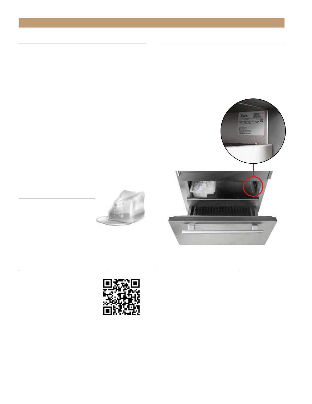
See the serial label inside the cabinet for the units
refrigeration type. For Hydrocarbon Refrigeration
(R290 only), see below:
DANGER – Risk of fire or explosion.
Flammable refrigerant used. DO NOT
use mechanical devices to defrost
refrigerator. DO NOT puncture refrigerant
tubing; follow handling instructions
carefully. To be repaired only by trained
service personnel.
DANGER – Risk of fire or explosion
(flammable refrigerant used), consult
repair manual/owner’s guide before
attempting to service this product. All
safety precautions must be followed.
Dispose of properly in accordance with
local and federal regulations. Follow all
safety precautions.
CAUTION – Keep all ventilation openings
clear of obstruction in the appliance
enclosure or in the structure housing the
appliance.
BASIC SAFETY & WARNING
PRECAUTIONS
• Take care during operation, maintenance or
repairs to avoid cuts or pinching from any part/
component of the cabinet.
• Units may pose a tipping hazard while uncrating,
during installation, or when moving the unit.
• Ensure the unit is properly installed and located
in accordance with the Installation Instructions
before use.
• This appliance is not to be used, cleaned or
maintained by persons (including children) with
reduced physical, sensory or mental capabilities
or lack of experience and knowledge, unless they
have been given supervision or instruction.
• DO NOT allow children to play with the appliance
or climb, stand, or hang on the unit’s shelves to
prevent damage to the refrigerator and personal
injury.
• DO NOT touch the cold surfaces in the freezer
compartment when hands are damp or wet. Skin
may stick to these extremely cold surfaces.
• Unplug the refrigerator before cleaning and
making repairs.
• Setting temperature controls to the 0 position or
powering off an electronic control may not remove
power from all components (e.g., light circuits,
perimeter heaters, and evaporator fans).
• DO NOT store or use gasoline, or other flammable
vapors and liquids, in the vicinity of this or any
other appliance.
• DO NOT store explosive substances such as aerosol
cans with a flammable propellant in this appliance.
• Keep fingers out of the "pinch point" areas;
clearances between the doors and cabinet are
necessarily small; be careful closing doors when
children are in the area.
• DO NOT use electrical appliances inside the food
storage compartments of the units unless the
appliances are of the type recommended by the
manufacturer.
NOTE: ALL SERVICING MUST BE PERFORMED BY A
QUALIFIED TECHNICIAN.
HOW TO MAINTAIN YOUR TRUE REFRIGERATOR TO RECEIVE THE MOST
EFFICIENT AND SUCCESSFUL OPERATION
SAFETY INFORMATION AND OWNERSHIP

TR-36RBF INSTALL GUIDE
07/28/2021 Page 7 of 48TEC_TM_151 | REV. A | EN
CABINET DISPOSAL WARNING
DANGER! RISK OF CHILD
ENTRAPMENT
PROPER DISPOSAL OF THE CABINET
Child entrapment and suffocation are not problems of
the past. Junked or abandoned refrigerators are still
dangerous, even if they will sit for "just a few days." If
you are getting rid of your old refrigerator, please follow
the instructions below to help prevent accidents.
Before throwing away your old refrigerator or freezer:
• Take off the doors.
• Leave the shelves in place so that children may not
easily climb inside.
DANGER – Risk of fire or explosion.
Flammable insulation and/or refrigerant
used. Dispose of all in accordance with
local and federal regulations. Follow all
safety precautions.
SAFETY INFORMATION AND OWNERSHIP

TRUE RESIDENTIAL®TEC_TM_151 | REV. A | EN07/28/2021Page 8 of 48
OWNERSHIP
To ensure that your unit works properly from the
first day, it must be installed properly. We highly
recommend a trained refrigeration mechanic and
electrician install your True equipment. The cost of a
professional installation is money well spent.
Before you start to install your TRUE unit, carefully
inspect it for freight damage. If damage is
discovered, immediately file a claim with the delivery
freight carrier.
TRUE is not responsible for damage incurred during
shipment.
For any questions about installation, please contact
your True dealer or True Residential Technical
Service at 844-746-9423 or TrueResidentialService@
TrueMfg.com. Please have your model and serial
number available.
NOTICE TO CUSTOMER
Loss or spoilage of products in
your refrigerator/freezer is not
covered by warranty. In addition
to following recommended
installation procedures, run the refrigerator/freezer
for 24 hours prior to usage to verify its proper
operation.
REGISTER YOUR PRODUCT
To qualify for TRUE’s extended
7–12 year parts only sealed
system warranty, you must
register your product* within 12
months of the unit’s installation
date. To register your unit,
complete and submit the form
at https://www.true-residential.com/product-registration.
For warranty details, please see page 47.
SERIAL LABEL LOCATION
The serial label is located on the upper right wall of the
freezer drawer. See fig. 1.
This label contains important information such as
your model name and serial number. Please have this
information on hand when contacting True so we can
better assist you with your service- or parts-related
inquiries.
SAFETY INFORMATION AND OWNERSHIP
FIG. 1.
Serial label location.
CONTACT INFORMATION
WARRANTY DEPARTMENT
Phone: 844-849-6179
TrueResidentialWarranty@truemfg.com
CUSTOMER SERVICE
Phone: 888-616-8783
info@true-residential.com
SERVICE DEPARTMENT
Phone: 844-746-9423
TrueResidentialService@truemfg.com
* Please note that ice machines do not qualify for this
extended warranty.

TR-36RBF INSTALL GUIDE
07/28/2021 Page 9 of 48TEC_TM_151 | REV. A | EN
ROUGH OPENINGS & PLAN VIEWS
ANTI-SWEAT FOAM END PANELS
ELECTRICAL SAFETY & INSTALLATION REQUIREMENTS
WATER SUPPLY REQUIREMENTS
PRESERVE THE MOMENT®
SITE PREPARATION

TRUE RESIDENTIAL®TEC_TM_151 | REV. A | EN07/28/2021Page 10 of 48
SITE PREPARATION
SITE PREPARATION
Due to the weight of this unit, True recommends
consulting a flooring expert prior to installation.
The flooring beneath the unit should be rated to
support ≥150 lbs/ft2(732.36 kg/m2).
ROUGH OPENINGS & PLAN VIEWS
TR-36RBF
Flush installation: The front face of the unit is flush
with the surrounding cabinets
Proud (standard) Installation: The front face of the
unit extends beyond the surrounding cabinets
NOTE: DIMENSIONS MAY VARY BY ± 1/8” (3.175 mm)
Rough Opening Dimensions
Flush Install Proud Install
Width 36-1/4”
(920.75 mm)
35-3/4”
(908.05 mm)
Depth 25-25/32”
(654.84 mm)
23-25/32”
(604.04 mm)
Height 84-1/4”
(2,139.95 mm)
84”
(2,133.6 mm)
ELECTRICAL AREA
WATER AREA

TR-36RBF INSTALL GUIDE
07/28/2021 Page 11 of 48TEC_TM_151 | REV. A | EN
SITE PREPARATION
ROUGH OPENINGS & PLAN VIEWS
TR-36RBF / TR-36RBF
Flush installation: The front face of the unit is flush
with the surrounding cabinets
Proud (standard) Installation: The front face of the
unit extends beyond the surrounding cabinets
NOTE: DIMENSIONS MAY VARY BY ± 1/8” (3.175 mm)
Rough Opening Dimensions
Flush Install Proud Install
Width 72-1/4”
(1,835.15 mm)
71-3/4”
(1,822.45 mm)
Depth 25-25/32”
(654.84 mm)
23-25/32”
(604.04 mm)
Height 84-1/4”
(2,139.95 mm)
84”
(2,133.6 mm)
ELECTRICAL AREA
WATER AREA

TRUE RESIDENTIAL®TEC_TM_151 | REV. A | EN07/28/2021Page 12 of 48
SITE PREPARATION
ANTI-SWEAT FOAM END PANELS
When installing two or more True units side-by-side, be sure to leave at least a 5/8” (15.88 mm) gap
between the cabinets, or install foam pads between the cabinets and on any side with 0” clearance,
to prevent moisture from developing on applications.
If installing anti-sweat foam end panels, True recommends applying a panel to each of the units
being joined together. To order foam pads, contact our parts department at 844-849-6226 or
TrueResidentialParts@TrueMfg.com.
NOTE: DIMENSIONS MAY VARY BY ± 1/8” (3.175 mm)

TR-36RBF INSTALL GUIDE
07/28/2021 Page 13 of 48TEC_TM_151 | REV. A | EN
SITE PREPARATION
ELECTRICAL SAFETY
Power Supply: 115VAC, 60hz
Circuit Breaker: 15 Amp
Receptacle: 3-Prong Grounding-Type
• For all built-in models, the electrical supply should
be located within the indicated shaded area shown
in the figure below.
• Be sure to follow the National Electrical Code, as
well as local codes and ordinances, when installing
the receptacle.
• A ground fault circuit interrupter (GFCI) is not
recommended and may cause interruption of
operation.
• The power cord from this appliance is equipped
with a grounding plug which minimizes the
possibility of electric shock hazard.
• The wall outlet and circuit should be checked by a
licensed electrician to be sure the outlet is wired
with the correct polarity and properly grounded.
• If the outlet is a standard 2-prong outlet, it is your
personal responsibility and obligation to have it
replaced with a properly grounded wall outlet.
• DO NOT, under any circumstances, cut or remove
the ground prong from the power cord. For personal
safety, this appliance must be properly grounded.
• The refrigerator/freezer should always be plugged
into a dedicated electrical circuit. This provides
the best performance and prevents building wiring
circuits from overloaded, which could cause a fire
hazard from overheated wires.
• NEVER USE AN ADAPTER PLUG!
An adapter plug alters the original
equipment manufacturer (OEM)
plug configuration when connecting
it to a power source. True will not warranty any
refrigerator/freezer that has been connected
to an adapter plug.
• NEVER USE AN EXTENSION CORD! An
extension cord is any component that
adds length to the OEM power cord
when connecting it to a power source.
True will not warranty any refrigerator/freezer that
has been connected to an extension cord.
• Before your new unit is connected to a power
supply, check the incoming voltage. If the recorded
voltage is less than the rated voltage for operation
(+/-5%) and amp rating, correct immediately. Refer
to the serial label for this voltage requirement.
• NEVER unplug your refrigerator/freezer by pulling
on the power cord. Always grip the plug firmly and
pull straight from the outlet.
• When moving the refrigerator/freezer for any reason,
take care to no roll over or damage the power cord.
• Immediately repair or replace all power cords
that have become frayed or otherwise damaged.
DO NOT use a power cord that shows cracks or
abrasion damage along its length or at either end.
• If the supply power cord is damaged, replace it
with OEM components. To avoid hazard, this should
be done by a licensed service provider or similarly
qualified person.
ELECTRICAL AREA
NOTE: DIMENSIONS MAY VARY BY ± 1/8” (3.175 mm)

TRUE RESIDENTIAL®TEC_TM_151 | REV. A | EN07/28/2021Page 14 of 48
SITE PREPARATION
POWER CORD
INSTALLATION
Fully seat the power cord into the cabinet receptacle
until it locks in position. See fig. 1.
REMOVAL
Depress the red button. See fig. 2.
FIG. 1.
Fully insert the power
cord into the receptacle.
FIG. 2.
Push the red button to
remove the plug.

TR-36RBF INSTALL GUIDE
07/28/2021 Page 15 of 48TEC_TM_151 | REV. A | EN
SITE PREPARATION
FIG. 1.
Water line connection. Fitting included, PEX not included
Plumbing Requirements
Water Supply
1/4” PEX tubing (1/4” O.D. lines and
fittings not included)
NOTE: Copper line is not recommended.
Flow Rate 0.5 gpm / 1.89 lpm
Operating Pressure 30 psi (207 kPa)—100 psi (689 kPa)
Incoming Water
Temperature 33-100°F (0.6-38°C)
WATER SUPPLY REQUIREMENTS
The unit comes with 20” (508 mm) of polyethylene
tubing with a 1/4” O.D. push connector for customer
attachment.
Before installing your unit, prepare the water supply
line. Please see plumbing requirements in the
plumbing requirements table.
• Purge the water line prior to final connection to
the unit. This removes any debris present in the
line.
• Only connect to a potable water supply!
• Do not connect to a hot water supply!
• Install the water filter before turning on the
water supply to the icemaker. See “Water Filter
Installation” (page 19).
• A copper line is not recommended for this
application.
• Check all water line fittings for leaks.
• Tape the supply line to the floor before moving
the unit into its final installation location.
• In the water connection area (see the rough
opening illustration), tape the water line to the
floor.
WATER AREA
NOTE: DIMENSIONS MAY VARY BY ± 1/8” (3.175 mm)

TRUE RESIDENTIAL®TEC_TM_151 | REV. A | EN07/28/2021Page 16 of 48
INSTALLATION
ANTI-TIP BRACKET INSTALLATION
LEVELING
WATER FILTER INSTALLATION & PERFORMANCE DATA
KICKPLATE INSTALLATION
PRESERVE THE MOMENT®

TR-36RBF INSTALL GUIDE
07/28/2021 Page 17 of 48TEC_TM_151 | REV. A | EN
WARNING – To avoid a hazard from
appliance instability, install the anti-
tip bracket in accordance with the
instructions below.
BEFORE YOU BEGIN
Consult a flooring expert to confirm that the flooring
where the unit will be installed is rated for at least 150
pounds per square foot.
1. Measure and mark the depth of the bracket’s
placement in the installation location.
• Flush installation: 24-31/32” (634 mm)
• Proud installation: 22-31/32” (584 mm)
2. Place and center the bracket at the measured
depth.
3. With the bracket as a guide, drill pilot holes into the
wall and/or floor.
NOTE: FOR INCREASED STABILITY, SECURE THE
BRACKET TO AS MANY JOISTS AND/OR STUDS AS
POSSIBLE.
4. With the provided hardware, secure the anti-tip
bracket.
5. Adjust the rear leveling rollers 1/4 turn clockwise.
6. Slide the unit into place and hook the anti-tip
bracket into the castor assembly slots.
INSTALLATION
ANTI-TIP BRACKET KIT:
• One (1) anti-tip bracket (Figure 1.1)
• Four (4) masonry 3/16” screws
• Eight (8) wood #12 – 2” screws
• Twelve (12) 1/4” washers
FOR ALL FULL SIZE RESIDENTIAL MODELS, THE ANTI-
TIP BRACKET ENGAGES WITH THE REAR LEVELING
LEGS TO SECURE THE UNIT. FOLLOW THESE STEPS
TO SECURE THE BRACKET BEFORE MOVING THE
UNIT INTO FINAL OPERATING POSITION.
1. Determine final location of the unit. For a FLUSH
install, measure back 24-31/32” (Dimension A)
from the surrounding cabinetry. For a PROUD
install, measure back 22-31/32” (Dimension B)
from the surrounding cabinetry. For either type of
install, place the anti-tip bracket centered in the
rough opening.
2. Using the bracket as a guide, drill pilot holes into the
wall/floor. It is recommended to secure the bracket
to as many floor joists and wall studs as possible.
3. Using the provided screws and washers, secure the
bracket to the wall/floor. Adjust the rear rollers to
just above their lowest position and move the unit to
its final position. Raise the rear rollers a minimum
of 1/8” to engage the bracket.
FIGURE 1.1 - ANTI-TIP BRACKET
987036
5.19.17 AL
TRUE RESIDENTIAL REFRIGERATION
UPRIGHT ANTI-TIP BRACKET INSTALLATION
30 INCH UNIT
22 31/32"
583mm
PROUD INSTALL
24 31/32"
634mm
FLUSH INSTALL
9 9/32"
236mm
9 9/32"
236mm
C
LC
L
TR-30REF-R-SG-A
R
NOTE: DIMENSIONS MAY VARY BY ± 1/8”
WARNING: To avoid a hazard due to instability of
the appliance, it must be fixed in accordance with
the instructions.
AVERTISSEMENT: Pour éviter tout risque dú a
l´instabilité del l´appareil, vous devez le fixer
conformément aux instructions.
ANTI-TIP BRACKET INSTALLATION
KIT INCLUDES
• (1) One anti-tip bracket
• (4) Four 3⁄16” masonry screws
• (8) Eight #12-2” wood screws
• (12) Twelve 1/4” washers
TOOLS REQUIRED
• Tape measure
• Marking utensil
• 1/8” drill bit
• 7/16” socket
• Phillips bit driver
• Drill or ratchet
36RBF UNIT TOP VIEW
= Center Line
–-– = Bracket Location
NOTE: DIMENSIONS MAY VARY BY ± 1/8” (3.175 mm)

TRUE RESIDENTIAL®TEC_TM_151 | REV. A | EN07/28/2021Page 18 of 48
INSTALLATION
FIG. 1.
Leveling leg adjustment locations.
LEVELING
It is important that your unit is level. This ensures the
doors align and seal correctly and drain pans do not
spill over.
1. Place a level on the interior floor on the unit. Check
the level back-to-front and side-to-side. See fig. 1
for leveling adjustment locations.
2. Adjust the front leveling legs as needed with pliers
or an adjustable wrench.
3. Adjust the rear leveling legs as needed with a 7/16”
socket. Turn clockwise to raise the rear of the unit.
Front leg adjustment
Rear leg adjustment

TR-36RBF INSTALL GUIDE
07/28/2021 Page 19 of 48TEC_TM_151 | REV. A | EN
INSTALLATION
WATER FILTER INSTALLATION &
PERFORMANCE DATA
The water filter filters sediment and removes
unpleasant taste and odor. Install the provided water
filter before using the icemaker. The unit will not make
ice until the water filter is installed.
1. Remove the kickplate. See fig. 1.
2. Insert the provided water filter (see fig. 2) and
rotate the filter clockwise. See figs. 3 and 4.
3. Reinstall the kickplate.
WATER FILTER PERFORMANCE DATA
• This system has been tested according to NSF/ANSI
Standard 42, 53, 372, 401, P473 and CSA B483.1
for reduction of the substances listed below. The
concentration of the indicated substances in water
entering the system was reduced to a concentration
less than or equal to the permissible limit for
water leaving the system, as specified in NSF/
ANSI Standards 42, 53, 372, 401, P473 and CSA
B483.1.
• Systems certified for cyst reduction may be used
on disinfected waters that may contain filterable
cysts. The system conforms to NSF/ANSI 42, 53,
372, 401,P473 and CSA B483.1 for the specific
performance claims as verified and substantiated
by test data. Conforms to NSF/ANSI 53 for VOC
reduction. See below for individual contaminants
and reduction performance.
NOTE: TESTING WAS PERFORMED UNDER
STANDARD LABORATORY CONDITIONS, ACTUAL
PERFORMANCE MAY VARY.
• System to be used with municipal or well water
sources treated and tested on regular basis to
ensure bacteriological safe quality. Do not use with
water that is microbiologically unsafe or of unknown
quality without adequate disinfection before or after
the system.
• It is essential that the manufacturer’s
recommended installation, maintenance and filter
replacement requirements be carried out for the
product to perform as advertised. Manufactured by
Aquamor, LLC, Temecula, CA.
FIG. 4.
Installed water filter.
FIG. 3.
Insert the water filter and rotate it clockwise.
FIG. 2.
Locate the provided water filter shipped in the ice bucket.
FIG. 1.
Pull the kickplate from the cabinet.

TRUE RESIDENTIAL®TEC_TM_151 | REV. A | EN07/28/2021Page 20 of 48
INSTALLATION
Filter Specifications
Flow Rate 0.5 gpm / 1.89 lpm
Operating
Temperature 33-100°F (0.6-38°C)
Operating Pressure 30-100 psi (kPa)
Capacity 300 gal (1,136 L) or six months
Contaminant and Reduction Performance
A-1, G-1, G-2, G-3, G-4, L-1, L-2, L-3, L-4, L-5,
M-1, M-2, S-1, S-2, S-4, W-2, W-3, W-4
Performance Data Sheet
Aquamor • 42188 Rio Nedo • Temecula, California 92590 • www.aquamorusa.com • 866-218-8473
Flow Rate: 0.5 gpm / 1.89 lpm
Operating Temperature: 33 - 100°F (0.6°C - 38°C)
Operating Pressure: 30 psi (207 kPa) - 100 psi (689 kPa)
Capacity: 300 gallons (1,136 L) or six months
Filter Specifications
This system has been tested according to NSF/ANSI Standard 42, 53, 372, 401, P473 and CSA B483.1 for reduction of the substances listed
below. The concentration of the indicated substances in water entering the system was reduced to a concentration less than or equal to the
permissible limit for water leaving the system, as specified in NSF/ANSI Standards 42, 53, 372, 401, P473 and CSA B483.1.
Systems certified for cyst reduction may be used on disinfected waters that may contain filterable cysts. The system conforms to NSF/ANSI 42, 53, 372, 401,
P473 and CSA B483.1 for the specific performance claims as verified and substantiated by test data. Conforms to NSF/ANSI 53 for VOC reduction. See above
for individual contaminants and reduction performance. Note: Testing was performed under standard laboratory conditions, actual performance may vary.
System to be used with municipal or well water sources treated and tested on regular basis to ensure bacteriological safe quality. Do not use with water that
is microbiologically unsafe or of unknown quality without adequate disinfection before or after the system.
It is essential that the manufacturer’s recommended installation, maintenance and filter replacement requirements be carried out for the product to perform
as advertised. Manufactured by Aquamor, LLC, Temecula, CA.
CHLORINE >97% 2.0 mg/L 1.0 mg/L
ALACHLOR* >98% 0.050 0.001
Asbestos 99.98% 189 MFL 99%
ATRAZINE* >97% 0.100 0.003
BENZENE* >99% 0.081 0.001
BISPHENOL 99.1% 2.058 mg/L <0.300ng/L
BROMODICHLOROMETHANE (TTHM)* >99.8% 0.300 0.015
BROMOFORM (TTHM)* >99.8% 0.300 0.015
CARBOFURAN (Furadan)* >99% 0.19 0.001
Carbon Tetrachloride >95% 0.014 0.005
CHLORDANE >99.5% 0.04 +/-10% 0.002
CHLOROBENZENE (Monochlorobenzene)* >99% 0.077 0.001
CHLOROPICRIN* 99% 0.015 0.0002
CHLOROFORM (TTHM)* (surrogate chemical) >99.8% 0.300 0.015
2, 4-D* 98% 0.110 0.0017
CYST
(Giardi; Cryptosporidium; Entamoeba; Toxoplasma)
>99.95%
MINIMUM 50,000/L
Cryptosporidium (see CYST)
>99.95% MINIMUM 50,000/L
DBCP (see Dibromochloropropane)* >99% 0.052 0.00002
1,2-DCA (see 1,2-DICHLOROETHANE)* 95% 0.088 0.0048
1,1-DCE (see 1,1-DICHLOROETHYLENE)* >99% 0.083 0.001
DIBROMOCHLOROMETHANE
(TTHM; Chlorodibromomethane)*
>99.8% 0.300 0.015
DIBROMOCHLOROPROPANE (DBCP)* >99% 0.052 0.00002
o-DICHLOROBENZENE (1,2 Dichlorobenzene)* >99% 0.080 0.001
p-DICHLOROBENZENE (para-Dichlorobenzene) >98% 0.040 0.001
1,2-DICHLOROETHANE (1,2-DCA)* 95% 0.088 0.0048
1,1-DICHLOROETHYLENE (1,1-DCE)* >99% 0.083 0.001
CIS-1,2-DICHLOROETHYLENE* >99% 0.170 0.0005
TRANS-1,2- DICHLOROETHYLENE* >99% 0.086 0.001
1,2-DICHLOROPROPANE (Propylene Dichloride)* >99% 0.080 0.001
CIS-1,3- DICHLOROPROPYLENE* >99% 0.079 0.001
DINOSEB* 99% 0.170 0.0002
EDB (see ETHYLENE DIBROMIDE)* >99% 0.044 0.00002
ENDRIN 99% 0.053 0.00059
Entamoeba (see CYSTS) 99.95%
MINIMUM 50,000/L
ESTRONE 96.9% 0.1388 mg/L <0.020 mg/L
ETHYLBENZENE* >99% 0.088 0.001
ETHYLENE DIBROMIDE (EDB)* >99% 0.044 0.00002
Furadan (see CARBOFURAN)* >99% 0.19 0.001
Giardia Lamblia (see CYST) >99.95%
MINIMUM 50,000/L
HALOACETONITRILES (HAN)*
BROMOCHLOROACETONITRILE 98% 0.022 0.0005
DIBROMOACETONITRILE 98% 0.024 0.0006
HALOACETONITRILES (HAN)*
DICHLOROACETONITRILE 98% 0.0096 0.0002
TRICHLOROACETONITRILE 98% 0.015 0.0003
% of Influent Max
Contaminant reduction Concentration Allowable
99.95% REDUCTION
REQUIREMENT
99.95% REDUCTION
REQUIREMENT
99.95% REDUCTION
REQUIREMENT
99.95% REDUCTION
REQUIREMENT
HALOKETONES (HK):*
1,1-DICHLORO-2-PROPANONE 99% 0.0072 0.0001
1,1,1-TRICHLORO-2-PROPANONE 96% 0.0082 0.0003
HEPTACHLOR* >99% 0.25 0.00001
HEPTACHLOR EPOXIDE* 98% 0.0107 0.0002
HEXACHLOROBUTADIENE (Perchlorobutadiene)* >98% 0.044 0.001
HEXACHLOROCYCLOPENTADIENE* >99% 0.060 0.000002
IBUPROFEN 96.7% 0.432 mg/L <0.060 mg/L
LEAD (pH 6.5) >99.3% 0.15 +/- 10% 0.010
LEAD (pH 8.5) >99.3% 0.15 +/- 10% 0.010
LINDANE* >99% 0.055 0.00001
METHOXYCHLOR* >99% 0.050 0.0001
Methylbenzene (see TOLUENE)* >99% 0.078 0.001
Mercury (pH 6.5) 74.9% 0.0059 0.002
Mercury (pH 8.5) 97.8% 0.0061 0.002
Monochlorobenzene (see CHLOROBENZENE)* >99% 0.077 0.001
NAPROXEN 95.3% 0.130 mg/L <0.020 mg/L
NONYLPHENOL 97.1% 2.058 mg/L <0.200 mg/L
POLYCHLORINATED BIPHENYLS
(PCBs, Aroclor 1260)
>99.9% 0.01 +/- 10% 0.0005
PCE (see Tetrachloroethylene) >96% 0.014 0.005
PENTACHLOROPHENOL* >99% 0.096 0.001
Perchlorobutadiene
(see HEXACHLOROBUTADIENE)*
>98% 0.044 0.001
PFOA 98.0% 0.0005 mg/L <0.00007 mg/L
PFOS 98.0% 0.001 mg/L <0.00007 mg/L
Phenytoin 94.7% 0.2173 mg/L <.030 mg/L
Propylene Dichloride
(see 1,2 -DICHLOROPROPANE)*
>99% 0.080 0.001
SIMAZINE* >97% 0.120 0.004
STYRENE (Vinylbenzene)* >99% 0.150 0.0005
1,1,1-TCA (see 1,1,1 - TRICHLOROETHANE)* 95% 0.084 0.0046
1,2,4-Trichlorobenze >99% 0.215 0.07
TCE (see TRICHLOROETHYLENE)* >99% 0.180 0.0010
1,1,2,2- TETRACHLOROETHANE* >99% 0.081 0.001
TETRACHLOROETHYLENE* >99% 0.081 0.001
TOLUENE (Methylbenzene)* >99% 0.078 0.001
TOXAPHENE >92.9% 0.015 +/- 10% 0.003
2,4,5-TP (Silvex)* 99% 0.270 0.0016
Toxoplasma (see CYST) >99.95%
MINIMUM 50,000/L
TRIBROMOACETIC ACID* 0.042 0.001
1,1,1-TRICHLOROETHANE (1,1,1-TCA)* 95% 0.084 0.0046
1,1,2-TRICHLOROETHANE* >99% 0.150 0.0005
TRICHLOROETHYLENE (TCE)* >99% 0.180 0.0010
TRIHALOMETHANES (TTHM)
(Chloroform; Bromoform;
Bromodichloromethane; Dibromochloromethane)
>99.8% 0.300 0.015
Unsym-Trichlorobenzene
(see 1,2,4-TRICHLOROBENZENE)
* >99% 0.160 0.0005
Vinylbenzene (see STYRENE)* >99% 0.150 0.0005
XYLENES (TOTAL)* >99% 0.070 0.001
% of Influent Max
Contaminant reduction Concentration Allowable
99.95% REDUCTION
REQUIREMENT
This manual suits for next models
1
Table of contents
Other True Freezer manuals
Popular Freezer manuals by other brands

LG
LG GR-B379PLQ owner's manual

Indel Webasto Marine
Indel Webasto Marine BI29 Dual Installation and operation manual

Gorenje
Gorenje FH401IW Instructions for use

Miele
Miele KFN 29683 D obsw Operating and installation instruction

Kernau
Kernau KFCF 1401 W User instruction

Beko
Beko HS221520F Instructions of use