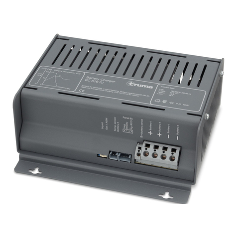
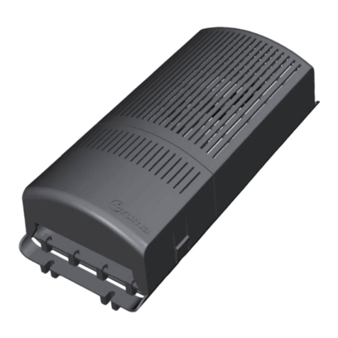
Truma BC 10 User manual

Einbauanweisung Seite 2
Im Fahrzeug mitzuführen!
Installation instructions Page 11
To be kept in the vehicle!
Instructions de montage Page 20
À garder dans le véhicule !
Istruzioni di montaggio Pagina 29
Da tenere nel veicolo!
Inbouwhandleiding Pagina 38
In het voertuig meenemen!
Monteringsanvisning Side 47
Skal medbringes i køretøjet!
Monteringsanvisning Sida 56
Skall medföras i fordonet!
Mover® PowerSet
Ladegerät BC 10

2
Inhaltsverzeichnis
Verwendete Symbole ............................................................ 2
Einbauanweisung
Glossar .................................................................................. 3
Sicherheitshinweise .......................................................... 3
Verwendungszweck .............................................................. 4
Netzanschluss ....................................................................... 4
Abmessungen / Gewicht (Ladegerät BC 10) ......................... 5
Lieferumfang: ........................................................................ 5
Anschlussschema .............................................................. 6
Platzwahl ............................................................................. 7
Anschlüsse .......................................................................... 7
Easy clicK® Polklemmen ....................................................... 7
Anschluss Ladegerät ............................................................ 8
Anschluss Temperaturfühler ................................................. 8
Einbau des Batterietrennschalters und Anschluss
der Batterie ............................................................................ 9
Inbetriebnahme ................................................................ 10
Netzbetrieb auf Fähren ....................................................... 10
Generatorbetrieb ................................................................. 10
Mover® PowerSet
Verwendete Symbole
Einbau und Reparatur des Gerätes dürfen nur vom
Fachmann durchgeführt werden.
Symbol weist auf mögliche Gefahren hin.
Hinweis mit Informationen und Tipps.

3
Vor Anschluss und Inbetriebnahme des Gerätes unbe-
dingt die Einbau- und Gebrauchsanweisung lesen!
Glossar
AGM-Batterie Blei-Säure-Batterie, bei der der
Elektrolyt in einem Mikroglasvlies
(Absorbed Glass Mat) festgelegt ist.
Batterie OPTIMA® YT S entspricht einer AGM-Batterie.
Sicherheitshinweise
Beim Gebrauch von elektrischen Geräten sind zum
Schutz vor elektrischem Schlag, Verletzung und Brand-
gefahr folgende grundsätzliche Sicherheitsmaßnahmen zu be-
achten. Lesen und beachten Sie diese Hinweise, bevor Sie
das Gerät benutzen.
Aufstellen
Achten Sie darauf, dass die Geräte sicher aufgestellt werden
und nicht herabfallen oder umstürzen können. Legen Sie
Leitungen stets so, dass keine Stolpergefahr entsteht. Setzen
Sie Elektrogeräte nicht dem Regen aus. Betreiben Sie Elektro-
geräte nicht in feuchter oder nasser Umgebung. Betreiben Sie
Elektrogeräte nicht in der Nähe von brennbaren Flüssigkeiten
oder Gasen. Stellen Sie Ihre elektrischen Geräte so auf, dass
Kinder keinen Zugriff darauf haben.
In diesem Gerät sind Bauteile eingebaut, die einen
Funken oder Lichtbogen erzeugen können!
Die Montage und der Anschluss von elektrischen Geräten
muss grundsätzlich durch geeignetes Fachpersonal erfolgen!
Stellen Sie sicher, dass die Stromzufuhr getrennt ist! Netz-
stecker ziehen!
Benutzen Sie zum Anschluss des Gerätes nur die mitgeliefer-
ten Teile sowie die vorgeschriebenen Leitungsquerschnitte
und Sicherungen!
Benutzen Sie nur geeignetes und einwandfreies Werkzeug.
Schließen Sie das Gerät nur gemäß des mitgelieferten An-
schlussplanes an!
Einbauanweisung

4
Schutz vor elektrischem Schlag
Betreiben Sie nur Geräte deren Gehäuse und Leitungen un-
beschädigt sind. Achten Sie auf sichere Verlegung der Kabel.
Ziehen Sie nicht an den Kabeln.
Den elektrischen Anschluss der Geräte über einen
Fehlerstromschutzschalter 30 mA Nennfehlerstrom ab-
sichern und nur so betreiben. Die jeweils geltenden örtli-
chen Installationsvorschriften beachten.
Gebrauch
Benutzen Sie keine elektrischen Geräte entgegen dem, vom
Hersteller angegebenen Verwendungszweck.
Instandsetzung
Nehmen Sie keine Instandsetzungsarbeiten oder Veränderun-
gen am Gerät vor. Wenden Sie sich an Ihren Händler oder an
den Truma Service (siehe Serviceheft oder www.truma.com).
Verwendungszweck
Das Ladegerät dient ausschließlich dem Laden von 12 V
Bleiakkumulatoren, bestehend aus 6 Einzelzellen (z. B. Auto-
batterie), mit einer Kapazität von 20 – 200 Ah. Es ist universell
einsetzbar und für Dauerbetrieb und Parallelbetrieb ausgelegt.
Das bevorzugte Einsatzgebiet des Ladegerätes sind Batterien
mit Gel-, AGM- oder Flüssigelektrolyt. Das Gerät ist für den
Einbau in Caravans bestimmt.
Netzanschluss
Der Anschluss des Versorgungsnetzes an das Gerät muss in
Übereinstimmung mit den jeweils geltenden nationalen Instal-
lationsvorschriften vorgenommen werden.
Der elektrische Anschluss 230 V darf nur vom Fachmann (in
Deutschland z. B. nach VDE 0100, Teil 721 oder IEC60364-7-721)
durchgeführt werden. Die hier abgedruckten Hinweise sind
keine Aufforderung an Laien, den elektrischen Anschluss her-
zustellen, sondern dienen dem von Ihnen beauftragten Fach-
mann als zusätzliche Information!
Das Netzkabel an die Netzverteilung des Caravans anschlie-
ßen bzw. den Netzstecker in die Steckdose einstecken.
Alle Anschlüsse auf festen Sitz prüfen.
5
Abmessungen / Gewicht (Ladegerät BC 10)
Gehäuse
Kunststoff Schutzart IP65
Länge
230 mm
Breite
95 mm
Höhe
50 mm
Gewicht
0,75 kg
Lieferumfang:
1 Ladegerät BC 10
4 Ladegerät-Befestigungsschrauben
1 Gebrauchsanweisung
1 Einbauanweisung
1Comfort Connect - Ringöse
1 Comfort Connect - Klemme
2 Easy clicK® Polklemmen
1 Temperaturfühler für Batterie (Kabellänge 1,6 m)
1 Beipack Temperaturfühler (Flausch- und Hakenband)
1 Batterietrennschalter
1 Beipack Batterietrennschalter (2 Kabelschuhe 6 mm²
Schrauben und Muttern)

6
Anschlussschema
9±1 Nm
ON
Schlüssel
entnehmen /
stecken
OFF
Ø 25 mm
Batterie Steuerung
1
2
34
5
6
7
8
910
≥ 10 mm
4
5
3b
3a
Bild 1
1 Ladegerät BC 10
2 Temperaturfühler mit Anschlusskabel
3 Easy clicK® Polklemmen
3a Comfort Connect - Ringöse
3b Comfort Connect - Klemme
4 Sicherung
5 Batterietrennschalter
6 Steuerung Mover® XT / XT2 / XT L / XT4
7 Steuerung Mover® SE R / TE R / SR oder Master für TE R4
8 Steuerung Mover® Slave TE R4
9 Massekabel ≥ 10 mm² (Minuspol Batterie / Chassis)
nicht im Lieferumfang enthalten
10 Montage Batterietrennschalter

7
Platzwahl
Der Aufstellungsort soll sauber, trocken und gut belüftet sein.
Bei Betrieb kann sich das Gehäuse auf ca. 75 °C erwärmen.
Halten sie daher einen Mindestabstand von 100 mm ein.
Der für das Gerät bereitgestellte Raum darf nachfolgende Ab-
messungen nicht unterschreiten, da der Mindestabstand von
rundum 100 mm gewährleistet sein muss.
Länge: 430 mm / Breite: 300 mm / Höhe: 150 mm
Der Einbauraum für das Gerät muss oben und seitlich mit Lüf-
tungsöffnungen versehen sein, die eine Gesamtöffnung von
100 cm² ergeben.
Flüssigelektrolytbatterien müssen in einer separaten Box mit
einer Entlüftung nach außen aufgestellt werden. Eine separate
Box ist bei Gel- und AGM-Batterien nicht notwendig. Die Ins-
tallationsvorschriften des Batterieherstellers beachten.
Das Gerät mit den vier mitgelieferten Befestigungsschrauben
sicher befestigen.
Gerät so montieren, dass es zum separaten Laden ent-
nommen und mit dem Comfort Connect - Klemme an
eine externe Batterie angeschlossen werden kann.
Das Gerät ist für den Betrieb in einer Umgebungstemperatur
bis 40 °C ausgelegt. Steigt die Geräteinnentemperatur durch
mangelnde Luftzirkulation oder zu hohe Umgebungstempera-
tur, so reduziert sich der Ladestrom automatisch stufenweise.
Anschlüsse
Vor dem Anschließen oder Trennen von Leitungen sind
die Versorgungsleitungen von Batterie und Netz zu trennen!
Nur vorgeschriebene Leitungsquerschnitte und Sicherungs-
stärken verwenden!
Easy clicK® Polklemmen
(rot = Pluspol, blau = Minuspol)
Zum schnellen Verbinden und Lösen von Batterieanschlüssen
von Hand. Passend für alle Anschlüsse nach DIN und SAE
Bild 2
Für den Anschluss des Ladekabels (Comfort Connect-
Ringöse) wird das Kabel mit den Ringösen an die
Polklemmen angeschraubt. Wird das Ladekabel nicht verwen-
det, Schutzkappe aufstecken.

8
Anschluss Ladegerät
Verbinden Sie das Ladegerät gemäß Anschlussplan (Bild 1)
mit der Batterie. Achten Sie auf den richtigen Anschluss der
Pole.
Die Minus-Ladestromleitung (schwarz) an den Minuspol und
die Plus-Ladestromleitung (rot) an den Pluspol der Batterie
anschließen.
Es wird empfohlen den Minuspol der Batterie mit dem Fahr-
zeugchassis zu verbinden – Mindestquerschnitt 10 mm².
Wird das Mover® PowerSet mit der autarken Elektroinstallati-
on des Fahrzeugs verschaltet, muss der Minuspol der Batte-
rie mit dem Fahrzeugchassis verbunden werden – Mindest-
querschnitt 10 mm².
Anschluss Temperaturfühler
Bringen Sie den beiliegenden Temperaturfühler mittig im
Bereich des Pluspols, am Gehäuse der Batterie an (Klebestel-
le zuvor reinigen). Hierzu entfernen Sie die Schutzfolie des
selbstklebenden Klettbandes (Hakenband mit Aussparung)
und drücken dieses kräftig auf die gewünschte Position an der
Batterie. Platzieren Sie den Fühler mittig in der Aussparung
und fixieren ihn mit dem zweiten Klettband (Flauschband).
Stecken Sie das Kabel des Temperaturfühlers an den Tempe-
raturfühleranschluss des Gerätes an (2-poliger Anschluss).
Bild 3

9
Einbau des Batterietrennschalters und
Anschluss der Batterie
Den Batterietrennschalter an geeigneter Stelle (Nähe Batterie)
in die Plusleitung zwischen Batterie und Steuerung einbauen.
– Für den Einbau ist ein Loch mit Ø 25 mm erforderlich.
– Schlüssel gegen den Uhrzeigersinn bis zur Endstellung
drehen und herausnehmen.
– Batterietrennschalter durch das Loch stecken und je nach
Untergrund mit geeigneten Schrauben sicher befestigen.
– Plusleitung der Batterie auftrennen und Kabelschuhe (im
Set enthalten) auf beide Enden des aufgetrennten Kabels
aufcrimpen.
– Den Schlüssel wieder einstecken und auf „OFF“ stellen.
Die Kabel mit den Kabelschuhen am Batterietrennschalter
anschrauben. Anschlussreihenfolge: Kabelschuh, Federring,
Mutter.
Nehmen Sie die weitere Montage gemäß der, jeweils
dem Gerät beigelegten, Einbauanweisung vor.
Sicherungen unbedingt nahe dem Pluspol der Batterie
anbringen!
Ø 25 mm
– +
Batterietrennschalter
Steuerung
Mover®
Batterie
≥10 mm²
ON
Schlüssel
entnehmen /
stecken
OFF
Batterie Steuerung
Bild 4

10
Inbetriebnahme
Zur Inbetriebnahme siehe die dem Gerät beiliegende
Gebrauchsanweisung.
Das Ladegerät ist in Betrieb sobald die Netzverbindung herge-
stellt ist.
Vor dem Unterbrechen oder Schließen von Gleichstromver-
bindungen, z. B. Ladestromkabel an der Batterie, ist das Gerät
netzseitig abzuschalten. Netzstecker ziehen!
Batterien mit Zellenschluss dürfen nicht geladen wer-
den. Explosionsgefahr durch Knallgasentwicklung!
Netzbetrieb auf Fähren
Die Netzspannung auf Fähren kann starken Schwankungen
unterworfen sein. Verbinden Sie daher das Gerät nicht mit
dieser Spannung.
Generatorbetrieb
Bitte beachten Sie die in der Betriebsanleitung des Herstellers
vorgegebene Handhabung. Der Generator muss die 230 V
Netzanschlusswerte einhalten. Schließen Sie das Gerät erst
dann an den Generator an, wenn dieser stabil läuft und tren-
nen Sie das Gerät von diesem, bevor Sie ihn abschalten. Die
in der Anlauf- und Abstellphase entstehenden Spannungsspit-
zen könnten das Gerät schädigen.

11
Table of contents
Symbols used ...................................................................... 11
Installation instructions
Glossary ............................................................................... 12
Safety instructions ........................................................... 12
Intended use ........................................................................ 13
Mains connection ................................................................ 13
Dimensions / Weight (BC 10 Charger) ................................ 14
Scope of delivery: ................................................................ 14
Connecting diagram ......................................................... 15
Selecting a location ......................................................... 16
Connections ...................................................................... 16
Easy clicK® terminal clamps ............................................... 16
Connecting the charger ....................................................... 17
Connecting the temperature sensor .................................... 17
Installing the battery cut-off switch and
connecting the battery ........................................................ 18
Start-up .............................................................................. 19
Mains operation on ferries .................................................. 19
Generator operation ............................................................ 19
Mover® PowerSet
Symbols used
The device must only be installed and repaired by an
expert.
Symbol indicates a possible hazard.
Note containing information and tips.

12
Before connecting and starting up the device, please be
sure to read the installation and operating instructions.
Glossary
AGM battery Lead-acid battery in which the elec-
trolyte is held in an Absorbed Glass
Mat.
Battery OPTIMA® YT S corresponds to an AGM battery.
Safety instructions
When using electrical devices, the following basic safe-
ty measures must be taken to provide protection from
electric shock, injury and the risk of fire. Please read and note
these instructions before using the device.
Set-up
Please ensure that the equipment is properly set up and can-
not fall over or fall down. Always route cables so that they do
not create a trip hazard. Do not leave electrical devices out in
the rain. Do not operate electrical devices in a damp or wet
environment. Do not operate electrical devices in the vicinity
of flammable liquids or gases. Position your electrical devices
out of the reach of children.
This device contains components that can generate a
spark or an arc!
The installation and connection of electrical devices must al-
ways be carried out by suitable electrical experts!
Make sure that the power supply has been disconnected. Pull
out the mains plug.
When connecting the device, only use the parts provided and
the specified line cross-sections and fuses.
Only use suitable tools that are in perfect condition.
Only connect the device as shown in the connection diagram
provided.
Installation instructions

13
Protection from electric shock
Do not use devices with damaged housings or cables. Please
ensure that the cables are properly routed. Do not pull on the
cables.
The electrical connection of the devices must be pro-
tected by a residual current device with a rated sensitiv-
ity of 30 mA, and must only be operated in this way. Any rel-
evant applicable local installation instructions must be
followed.
Usage
Please do not use the electrical device for any purpose other
than the one stipulated by the manufacturer.
Repairs
Do not make any repairs or modifications to the device.
Please contact your dealer or Truma Service (see service
booklet or www.truma.com).
Intended use
The battery charger must only be used to charge 12 V lead
batteries consisting of 6 individual cells (e.g. car battery) with
a capacity of 20 – 200 Ah. It is all-purpose and designed for
continuous and parallel operation. The battery charger is pri-
marily intended for charging gel, AGM or liquid electrolyte
batteries. The device is intended for installation in caravans.
Mains connection
The mains power supply must be connected to the device in
accordance with the relevant applicable national installation
instructions.
The 230 V electrical connection must always be made
by an expert (in accordance with VDE 0100, part 721 or
IEC60364-7-721, for example, in Germany). The instructions
shown here do not constitute a request to non-experts to
make the electrical connection, but serve as additional infor-
mation for an expert who is employed to do the work!
Connect the mains cable to the caravan’s power distributor or
plug the mains plug into the socket.
Check that all connections are firmly attached.

14
Dimensions / Weight (BC 10 Charger)
Housing
Plastic, protection class IP65
Length
230 mm
Width
95 mm
Height:
50 mm
Weight
0.75 kg
Scope of delivery:
1BC 10 charger
4Charger fastening screws
1Set of operating instructions
1Set of installation instructions
1Comfort Connect ring eyelet
1Comfort Connect clamp
2Easy clicK® terminal clamps
1 Temperature sensor for battery (cable length 1.6 m)
1 Temperature sensor accessory kit (hook and loop tape)
1 Battery cut-off switch
1 Battery cut-off switch accessory kit (2 cable eyelets 6 mm²
bolts and nuts)

15
Connecting diagram
9±1 Nm
ON
Take out /
insert key
OFF
Ø 25 mm
Battery Contr
ol unit
1
2
34
5
6
7
8
910
≥ 10 mm
4
5
3b
3a
Fig. 1
1 BC 10 charger
2 Temperature sensor with connector cable
3 Easy clicK® terminal clamps
3a Comfort Connect ring eyelet
3b Comfort Connect clamp
4 Fuse
5 Battery cut-off switch
6 Mover® XT / XT2 / XT L / XT4 control unit
7 Mover® SE R / TE R / SR control unit, or Master for TE R4
8 Mover® Slave TE R4 control unit
9 Earth cable ≥ 10 mm² (battery negative terminal / chassis)
not included
10 Battery cut-off switch assembly

16
Selecting a location
The installation site should be clean, dry and well ventilated.
The housing can heat up to approx. 75°C during operation, so
clearance of at least 100 mm must be left around the device.
In order to provide the minimum all-round clearance of
100 mm, the space provided for the device must have the
following minimum dimensions.
Length: 430 mm / width: 300mm / height: 150 mm
The space in which the device is installed must have venti-
lation openings at the top and the sides with a total opening
size of 100 cm².
Liquid electrolyte batteries must be installed in a separate box
with ventilation leading to the outside. A separate box is not
required for gel or AGM batteries. Pay attention to the battery
manufacturer’s installation instructions.
Attach the device securely using the four fastening screws
provided.
Install the device in such a way that it can be taken out
for separate charging and connected to an external bat-
tery using the Comfort Connect clamp.
The device is designed for use at ambient temperatures of up
to 40°C. If the internal temperature of the device increases
because of lack of air circulation or an ambient temperature
that is too high, the charging current is automatically reduced
in stages.
Connections
The supply lines from the battery and mains must be
disconnected before any cables are connected or dis-
connected. Only use the prescribed line cross-sections and
fuse strengths!
Easy clicK® terminal clamps
(red = positive terminal, blue = negative terminal)
Allow batteries to be connected and disconnected quickly by
hand. Suitable for all DIN and SAE connections
Fig. 2
In order to connect the charging cable (Comfort Connect
ring eyelet), the cable is screwed onto the terminal
clamps with the ring eyelets. If the charging cable is not used,
fit the protection cap.

17
Connecting the charger
Connect the charger to the battery as shown in the connec-
tion diagram (Fig.1). Ensure that the polarity is correct.
Connect the negative charging current cable (black) to the
negative terminal of the battery and the positive charging
current cable (red) to the positive terminal.
It is advisable for the negative terminal of the battery to be
connected to the vehicle chassis – minimum cross-section
10 mm².
If the Mover® PowerSet is connected to the independent elec-
trical installation of the vehicle, the negative terminal of the
battery must be connected to the vehicle chassis – minimum
cross-section 10 mm².
Connecting the temperature sensor
The provided temperature sensor must be attached to the bat-
tery housing in the centre of the area of the positive terminal
(having first cleaned the area to which it is to be attached).
Remove the protective film from the self-adhesive Velcro tape
(hook tape with cut-out) and press it firmly onto the desired
location on the battery. Place the sensor in the middle of
the cut-out and fasten in place with the second Velcro tape
(loop tape). Plug the cable from the temperature sensor in-
to the temperature sensor connection on the device (2-pin
connection).
Fig. 3

18
Installing the battery cut-off switch and
connecting the battery
Install battery cut-off switch in a suitable location (near the
battery) in the positive lead between the battery and the con-
trol unit.
– A hole with a Ø of 25 mm is required for installation.
– Turn key anticlockwise until it reaches the end position and
remove.
– Insert the battery cut-off switch through the hole and attach
securely using screws that are suitable for the underlying
surface.
– Cut the positive lead of the battery and crimp the cable eye-
lets (included in the set) onto both ends of the cut cable.
– Insert key again and turn to “OFF”. Bolt the cables with the
cable eyelets onto the battery cut-off switch. Connecting
order: Eyelet connector, spring washer, nut.
Proceed with installation as described in the installation
instructions supplied with the device concerned.
Fuses must be fitted near the positive terminal of the
battery. Fig. 4
Ø 25 mm
– +
Battery cut-o switch
Mover® control unit
Battery
≥10 mm²
ON
Take out /
insert key
OFF
Battery Control unit

19
Start-up
For start-up, see the operating instructions supplied with the
device.
The charger starts to operate as soon as it is connected to the
mains.
Switch the device off at the mains before interrupting or clos-
ing any DC connections, such as the charging cable on the
battery. Pull out the mains plug!
Batteries with short-circuits must not be charged.
Danger of explosion as a result of oxyhydrogen gas
emissions!
Mains operation on ferries
The mains voltage on ferries may fluctuate considerably.
Thedevice should therefore not be connected to this voltage.
Generator operation
Please use in accordance with the manufacturer’s operating
instructions. The generator must comply with the 230 V mains
supply values. Do not connect the device to the generator
until the latter is running steadily, and disconnect the device
from the generator before switching the latter off. Voltage
spikes in the start-up and shut-down phases may damage the
device.

20
Table des matières
Symboles utilisés ................................................................. 20
Instructions de montage
Glossaire .............................................................................. 21
Informations concernant la sécurité ............................. 21
Utilisation ............................................................................ 22
Raccordement au réseau ................................................... 22
Dimensions / poids (chargeur BC 10) .................................. 23
Volume de livraison : ........................................................... 23
Schéma de connexion ..................................................... 24
Choix de l'emplacement .................................................. 25
Connexions ........................................................................ 25
Bornes polaires Easy clicK® ................................................ 25
Raccordement chargeur ...................................................... 26
Raccordement sonde de température ................................ 26
Montage de l’interrupteur coupe-batterie
et raccordement de la batterie ........................................... 27
Mise en service ................................................................. 28
Fonctionnement sur secteur sur les ferries ......................... 28
Fonctionnement sur générateur .......................................... 28
Mover® PowerSet
Symboles utilisés
Le montage et la réparation de l’appareil doivent être
effectués uniquement par un spécialiste.
Ce symbole indique des risques possibles.
Remarque avec informations et conseils.
Table of contents
Languages:
Other Truma Batteries Charger manuals

Truma
Truma BC 616 IU User manual

Truma
Truma APC 310 User manual

Truma
Truma SC 3 User manual

Truma
Truma BC 630 IU User manual

Truma
Truma BC 430 IU User manual

Truma
Truma BC 860 IU User manual

Truma
Truma BC 416 IU User manual

Truma
Truma SDC 10 Operating instructions

Truma
Truma BC 616 IU Operating instructions
Popular Batteries Charger manuals by other brands

Boston Scientific
Boston Scientific Vercise DB-64125 Handbook

Cradlepoint
Cradlepoint PS6SMC70UE user guide

Motomaster
Motomaster 011-1504-0 instruction manual

Conceptronic
Conceptronic OZUL04BE Quick installation guide

Motorola solutions
Motorola solutions IMPRES 2 NNTN8845 Instruction leaflet

Voltech
Voltech BC-1240P-1 user manual