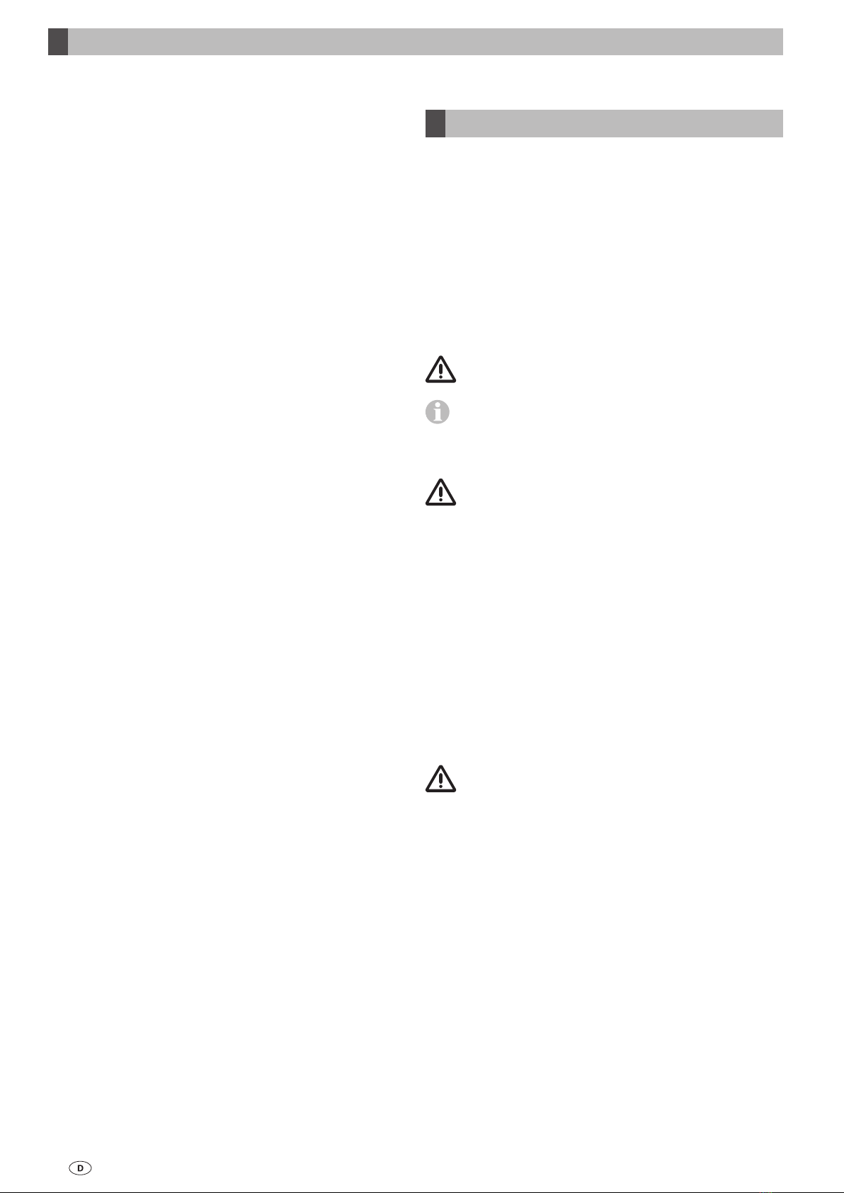
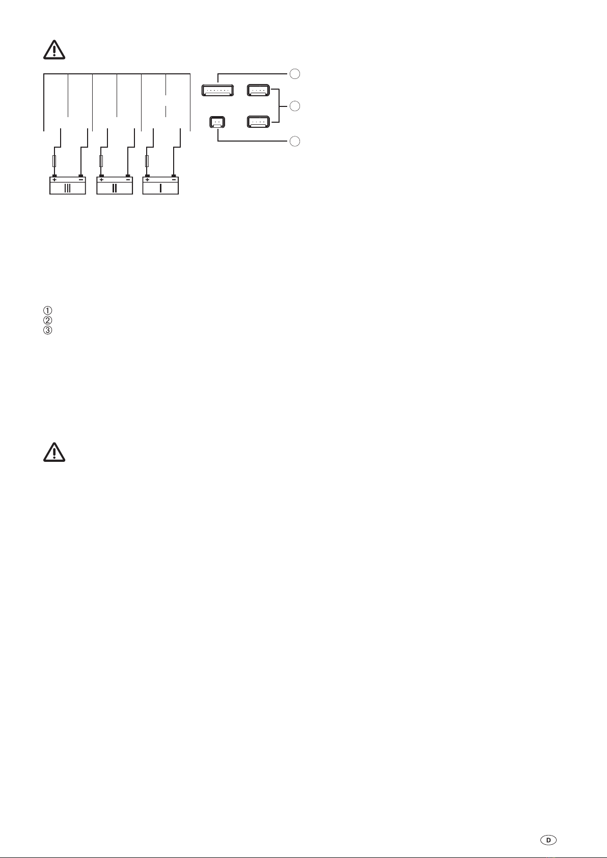
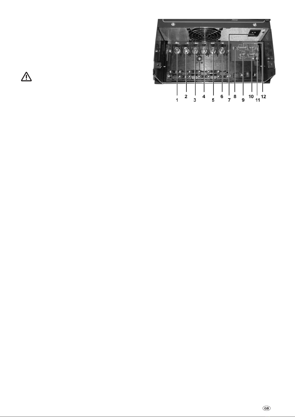
Truma BC 860 IU User manual

Komfort für Unterwegs
Gebrauchsanweisung Seite 2
Einbauanweisung
Operation instructions Page 8
Installation instructions
Mode d‘emploi Page 14
Instructions de montage
Istruzioni per l‘uso Pagina 20
Istruzioni di montaggio
Gebruiksaanwijzing Pagina 26
Inbouwhandleiding
Brugsanvisning Side 32
Monteringsanvisning
Instrucciones de uso Página 38
Instrucciones de montaje
Bruksanvisning Sida 44
Monteringsanvisning
Battery Charger BC 860 IU

2
Vor Anschluss und Inbetriebnahme des Gerätes unbe-
dingt die Einbau- und Gebrauchsanweisung lesen!
Glossar
AGM-Batterie Blei-Säure-Batterie, bei der der
Elektrolyt in einem Mikroglasvlies
(absorbed glass mat) festgelegt ist.
Batterie OPTIMA® YT S entspricht einer AGM-Batterie.
Verwendete Symbole
Symbol weist auf mögliche Gefahren hin.
Hinweis mit Informationen und Tipps.
Sicherheitshinweise
Beim Gebrauch von elektrischen Geräten sind zum
Schutz vor elektrischem Schlag, Verletzung und Brand-
gefahr folgende grundsätzliche Sicherheitsmaßnahmen zu
beachten. Lesen und beachten Sie diese Hinweise, bevor Sie
das Gerät benutzen.
Aufstellen
Achten Sie darauf, dass die Geräte sicher aufgestellt werden
und nicht herabfallen oder umstürzen können. Legen Sie
Leitungen stets so, dass keine Stolpergefahr entsteht. Setzen
Sie Elektrogeräte nicht dem Regen aus. Betreiben Sie Elektro-
geräte nicht in feuchter oder nasser Umgebung. Betreiben Sie
Elektrogeräte nicht in der Nähe von brennbaren Flüssigkeiten
oder Gasen. Stellen Sie Ihre elektrischen Geräte so auf, dass
Kinder keinen Zugriff darauf haben.
Schutz vor elektrischem Schlag
Betreiben Sie nur Geräte deren Gehäuse und Leitungen un-
beschädigt sind. Achten Sie auf sichere Verlegung der Kabel.
Ziehen Sie nicht an den Kabeln.
Den elektrischen Anschluss der Geräte über einen
Fehlerstromschutzschalter 30 mA Nennfehlerstrom
absichern und nur so betreiben. EVU-Vorschriften beachten.
Gebrauch
Benutzen Sie keine elektrischen Geräte entgegen dem, vom
Hersteller angegebenen Verwendungszweck.
Instandsetzung
Nehmen Sie keine Instandsetzungsarbeiten oder Verände-
rungen am Gerät vor. Wenden Sie sich an Ihren Händler oder
an den Truma Service (siehe Serviceheft oder www.truma.com).
Zubehör
Benutzen Sie nur Zubehörteile und Zusatzgeräte die vom Her-
steller geliefert oder empfohlen werden.
Inhaltsverzeichnis
Gebrauchsanweisung
Glossar .................................................................................. 2
Verwendete Symbole ............................................................ 2
Sicherheitshinweise .......................................................... 2
Verwendungszweck .............................................................. 3
Bestimmungswidriger Gebrauch .................................... 3
Beschreibung ...................................................................... 3
Anschlüsse .......................................................................... 3
Ladevorgang ....................................................................... 3
Wartung ............................................................................... 4
Entsorgung ............................................................................ 4
Technische Daten ............................................................... 4
Abmessungen / Gewicht ....................................................... 4
Ladekennlinie ...................................................................... 4
Fehlersuchanleitung .......................................................... 4
Zubehör ................................................................................ 5
Truma Hersteller Garantieerklärung ............................... 5
Einbauanweisung
Sicherheitshinweise .......................................................... 6
Aufstellen ............................................................................ 6
Anschluss ............................................................................ 6
Leitungslängen und -querschnitte ........................................ 6
Anschlussplan .................................................................... 7
Inbetriebnahme .................................................................. 7
Netzbetrieb auf Fähren ......................................................... 7
Generatorbetrieb .................................................................. 7
Ladeautomat BC 860 IU
Gebrauchsanweisung

3
Anschlüsse
Bild 1: Anschlüsse
1 Ausgang + Ladeleitung Batterie III
2 Ausgang - Ladeleitung Batterie III
3 Ausgang + Ladeleitung Batterie II
4 Ausgang - Ladeleitung Batterie II
5 Ausgang + Ladeleitung Batterie I – MASTER –
6 Ausgang - Ladeleitung Batterie I – MASTER –
7 Kaltgerätesteckeranschluss 230 V ~
8 Taster keine Funktion
9 Anschluss für Temperaturfühler
10 Anschluss für CAN BUS
11 Umschalter Gel- bzw. AGM (OPTIMA® YT S ) /
Flüssigelektrolytbatterie
12 Anschluss für Ladekontroll-Panel
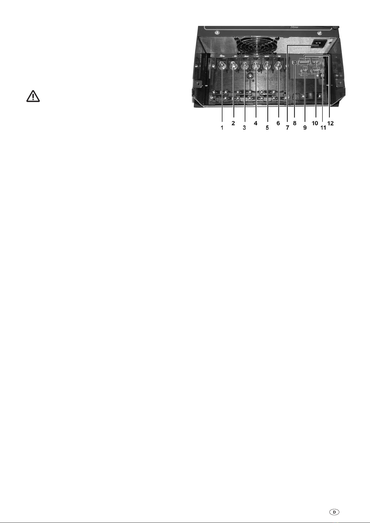
Ladevorgang
Nur wenn die Batterie richtig angeschlossen ist und eine Min-
destspannung von 1,5 V anliegt, wird der Ladestrom freigege-
ben. Es können bis zu 3 Batterien gleichzeitig angeschlossen
werden, der Gesamtladestrom (max. 60 A) darf dabei nicht
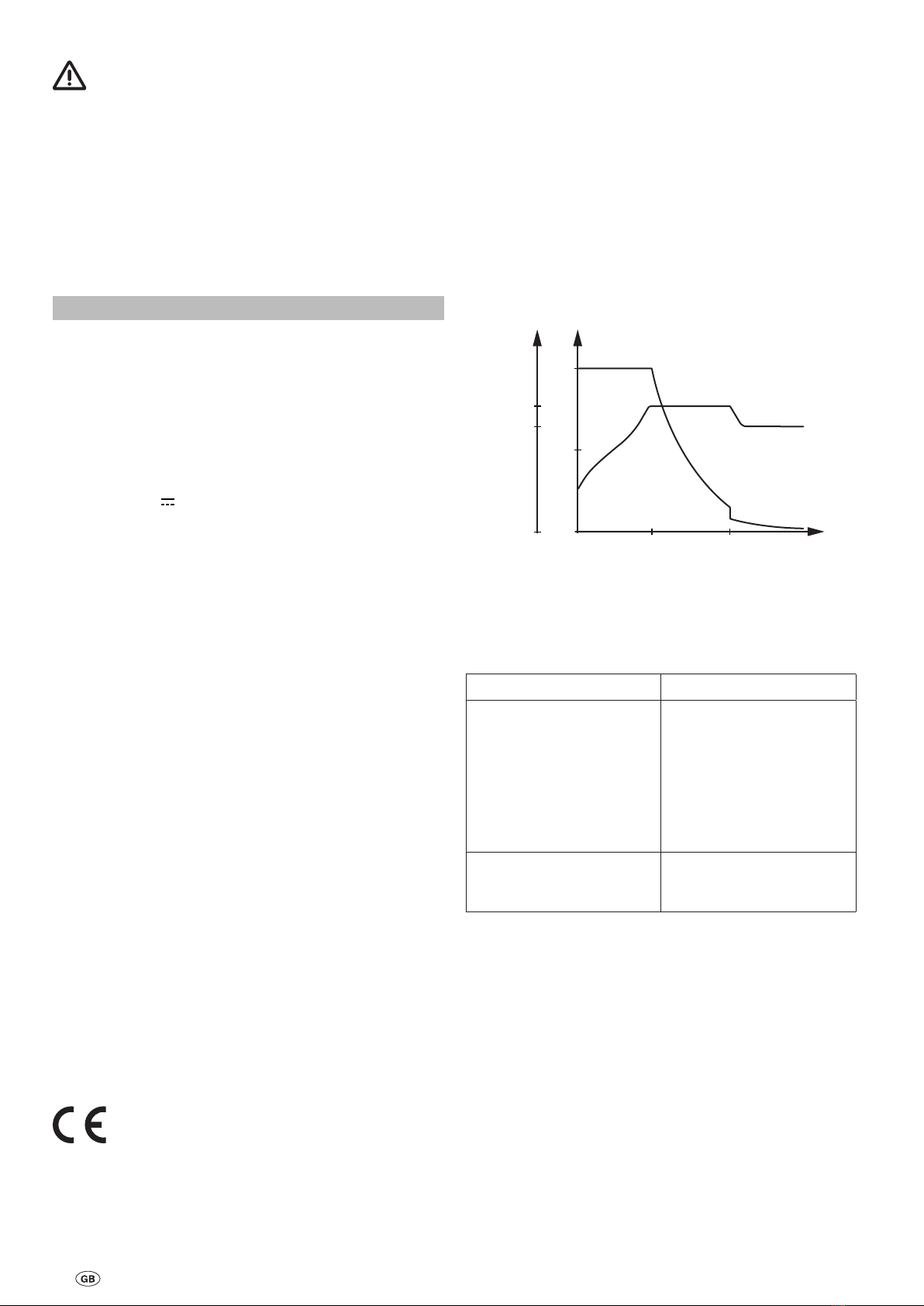
überschritten werden. Der Ladevorgang erfolgt gemäß der
Ladekennlinie unter geringster Verlustleistung (Ladekennlinie
siehe Bild 2).
Hauptladephase
(alle Spannungswerte bezogen auf 20 °C Batterietemperatur)
Ladung mit maximalem konstanten Ladestrom bis annähernd
14,4 V Batteriespannung erreicht sind. Sinkt in diesem Bereich
der Hauptladephase der Ladestrom bedingt durch den Batte-
rieinnenwiderstand und Leitungswiderstände unter 90 % des
Nennstromes ab, wird die Nachladephase gestartet.
Nachladephase
(alle Spannungswerte bezogen auf 20 °C Batterietemperatur)
Die Ladespannung wird über eine Zeitdauer von zehn Stun-
den bei Gel-Batterien / AGM bzw. vier Stunden bei Flüssige-
lektrolytbatterien konstant auf 14,4 V gehalten. Nach Ablauf
dieser Zeit erfolgt eine Umschaltung in die Erhaltungslade-
phase. Steigt während dieser Zeit der Strom auf über 90 %
des Nennstromes und sinkt dabei die Batteriespannung für
einen Zeitraum von mehr als 15 Minuten bei Flüssigelektro-
lytbatterien und mehr als zwei Stunden bei Gel-Batterie und
AGM unter 13,2 V, so erfolgt eine Umschaltung zurück in die
Hauptladephase.
Erhaltungsladephase
(alle Spannungswerte bezogen auf 20 °C Batterietemperatur)
Die Ladespannung ist auf 13,8 V eingestellt. Der Ladestrom
sinkt dabei auf den für die Batterie zur Ausgleichsladung
notwendigen Wert ab. Steigt der Ladestrom bedingt durch
Verbraucher auf seinen Nennwert und sinkt die Batteriespan-
nung für mindestens zwei Minuten unter 13,2 V, so schaltet
das Gerät wieder in die Hauptladephase zurück.
Parallelbetrieb
Wird während der Nachladephase oder der Erhaltungslade-
phase Verbraucherstrom entnommen, so wird dieser sofort
nachgeladen.
Verwendungszweck
Der Ladeautomat dient ausschließlich dem Laden von 12 V
Bleiakkumulatoren, bestehend aus 6 Einzelzellen (z. B. Auto-
batterie), mit einer Kapazität von 200 – 600 Ah. Er ist universell
einsetzbar und für Dauerbetrieb und Parallelbetrieb ausgelegt.
Das bevorzugte Einsatzgebiet des Ladeautomaten sind Batte-
rien mit Gel-, AGM oder Flüssigelektrolyt. Das Gerät ist für den
Einbau in Caravans, Motorcaravans und Boote bestimmt.
Bestimmungswidriger Gebrauch
Nicht für 6 V Batterien, oder nichtaufladbare Batterien
verwenden!
Der Ladeautomat darf nicht zum Laden von 6 V Bleiakkumu-
latoren verwendet werden. Werden Batterien mit einer Nenn-
spannung von 6 V mit dem Ladeautomat geladen, so setzt die
Gasung sofort ein. Es entsteht explosives Knallgas.
Der Ladeautomat darf nicht zum Laden von nichtaufladbaren
Batterien und / oder Nickel-Cadmium-Batterien verwendet
werden.
Beim Laden dieser Batteriearten, mit dem Ladeautomat, kann
die Hülle explosionsartig aufplatzen.
Beschreibung
Der Ladeautomat ist ein Produkt modernster, mikroprozes-
sorgesteuerter Ladetechnik. Diese Technik ermöglicht hohe
Leistung bei geringem Gewicht und kleinen Abmessungen.
Durch Verwendung hochwertiger Elektronik arbeitet er mit
einem hohen Wirkungsgrad. Das automatische Laden erfolgt
schonend und ohne schädliches Überladen der Batterie. So
wird die Lebensdauer der Batterie wesentlich verlängert. Nach
Herstellen des Batterieanschlusses und des Netzanschlusses
ist der Ladeautomat in Betrieb.
Der Ladeautomat ist für Dauerbetrieb und Parallelbetrieb
konzipiert. Verbraucher können ständig angeschlossen blei-
ben, dazugeschaltet oder weggeschaltet werden. Es werden
gleichzeitig die Verbraucher versorgt und die Batterie geladen.
Der Verbraucherstrom soll hierbei kleiner als der max. Lade-
strom sein, da sonst keine Ladung der Batterie erfolgt.
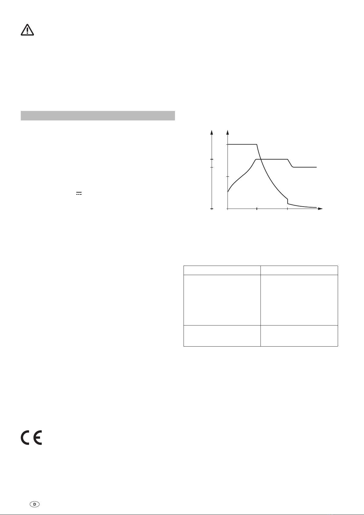
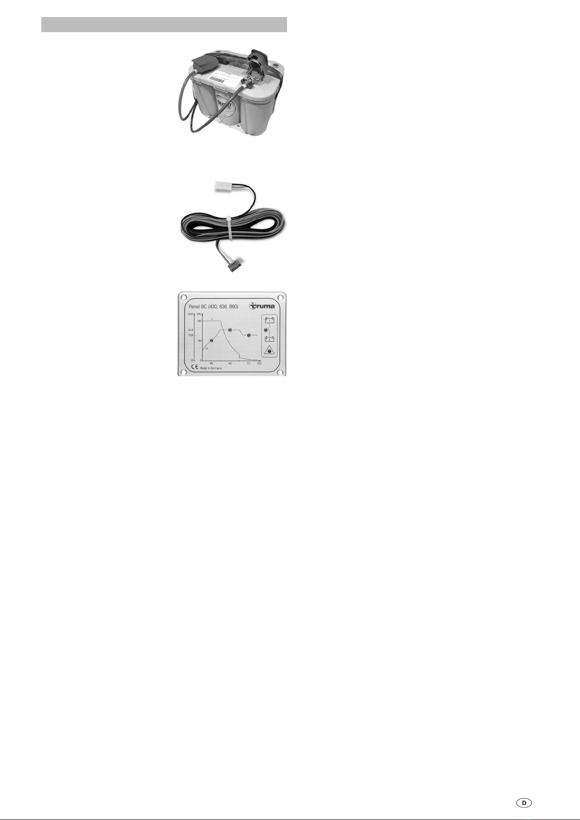
Unter Verwendung eines Ladekontroll-Panels, z. B. dem
Truma Panel BC (430, 630, 860) können die einzelnen Lade-
phasen sowie eventuelle Störungen des Ladeautomaten
angezeigt werden.
Wird der Ladeautomat zusammen mit einem Temperaturfühler
für die Batterie I (MASTER) betrieben so regelt der Ladeauto-
mat die Ladespannung automatisch in Abhängigkeit der Bat-
terietemperatur. Hierdurch wird eine besonders effektive und
schonende Ladung der Batterie erreicht. Ohne Verwendung
eines Temperaturfühlers regelt der Ladeautomat den Ladevor-
gang wie bei einer Batterietemperatur von 20 °C.
Das Gerät ist für den Betrieb in einer Umgebungstemperatur
bis 50 °C ausgelegt. Steigt die Geräteinnentemperatur durch
mangelnde Luftzirkulation oder zu hohe Umgebungstempe-
ratur über 50 °C, so reduziert sich der Ladestrom automatisch
auf 2/3, über 70 °C schaltet das Gerät aus.

4
Abmessungen / Gewicht
Gehäuse
Aluminium lackiert, belüftet
Länge
400 mm
Breite
290 mm
Höhe
110 mm
Gewicht
4,5 kg
Ladekennlinie
HL = Hauptladephase
NL = Nachladephase
EL = Erhaltungsladung
13,8
0
U[V]
14,4
0
50
100
I[%]
I
U
t[h]ELNLHL
Bild 2: Ladekennlinie (prinzipieller Verlauf)
Technische Änderungen vorbehalten.
Fehlersuchanleitung
Fehler Behebung
Die Batterie wird nicht
geladen. Prüfen Sie alle Anschlüsse
vom Ladeautomaten zur
Batterie, achten Sie dabei auf
die richtige Polung. Stecken
Sie den Kaltgerätestecker am
Gerät aus und wieder ein.
Prüfen Sie die Sicherungen
und den Netzanschluss.
Der maximale Ladestrom
wird nicht erreicht. Das Gerät wird zu warm,
sorgen Sie für bessere Belüf-
tung des Gerätes.
Sollten diese Maßnahmen nicht zur Störungsbehe-
bung führen, wenden Sie sich bitte an das Truma
Servicezentrum.
Wartung
Vor allen Wartungsarbeiten am Gerät unbedingt die
Stromzufuhr unterbrechen.
Reinigen Sie das Gerät und die Lüftungsschlitze mit einem tro-
ckenen, fusselfreien Tuch.
Entsorgung
Das Gerät ist gemäß den administrativen Bestimmungen des
jeweiligen Verwendungslandes zu entsorgen. Nationale Vor-
schriften und Gesetze (in Deutschland ist dies z. B. die Altfahr-
zeug-Verordnung) müssen beachtet werden.
Technische Daten
Spannungsversorgung
Wechselspannung 230 V / 50 Hz, einphasig
Bereich ca. 97 V – 250 V / 50 – 60 Hz
Ausgangsstrom
Ladestrom max. 60 A, arithmetischer Mittelwert, elektronisch
geregelt entsprechend der Ladekennlinie IUoU.
Verteilt auf die Ausgänge 1…3, in Abhängigkeit vom Ladezu-
stand der angeschlossenen Batterien.
Ausgangsspannung
Gleichspannung 12 V
Ladevorgang
Automatisch
Schaltautomatik (Hauptladevorgang)
AUS bei Batteriespannung 14,4 V, Ladestrom < 54 A
Schaltautomatik (Nachladephase)
10 Stunden konstant 14,4 V bei Gel-Batterien / AGM.
4 Stunden konstant 14,4 V bei Flüssigelektrolytbatterien.
Schaltautomatik (Erhaltungsladung)
Erhaltungsladung konstant 13,8 V
Temperaturabhängige Regelung (optional)
Die Werte der Schaltautomatik beziehen sich auf eine Batte-
rietemperatur von 20 °C. Unter Verwendung des Temperatur-
fühlers an der Batterie I variieren diese Werte in Abhängigkeit
von der Batterietemperatur.
Hohe Temperatur –> Absenkung der Schwellwerte.
Niedere Temperatur –> höhergestellte Schwellwerte.
Anwendung
Parallelbetrieb, allgemeiner Ladebetrieb.
Temperatur
Umgebungstemperatur von -25 °C bis +50 °C.
Bei Betrieb kann sich das Gehäuse auf ca. 75 °C erwärmen.
Kühlung
Durch temperaturgesteuerten Lüfter.
Ausführung
Gemäß den Bestimmungen des VDE und des
Gerätesicherheitsgesetzes.
Verwendung
Zum Laden von Batterien mit 12 V Nennspannung und einer
Kapazität von 200 – 600 Ah.

5
Zubehör
Quickpower Polklemmen
Zum schnellen Verbinden und
Lösen von Batterieanschlüs-
sen von Hand. Passend für alle
Anschlüsse nach DIN und SAE
(Art.-Nr. C11000-02100).
Temperaturfühler für Batterie I – MASTER –
Ermöglicht eine temperaturgeführte Batterieladung
Temperaturfühler mit
2 m Anschlusskabel und
Befestigungsmaterial
(Art.-Nr. C11000-00700).
Temperaturfühler mit
6 m Anschlusskabel und
Befestigungsmaterial
(Art.-Nr. C11000-00800).
Ladekontroll-Panel
Panel BC (430, 630, 860) zur
Anzeige der Ladephasen, der
Parallelschaltung von Starter-
und Versorgungsbatterie und
Störungen im Ladebetrieb
in Verbindung mit dem Lade-
automaten BC 630 IU.
Panel BC (430, 630, 860) mit
7-poligem Steuerkabel 5 m
und Befestigungsschrauben
(Art.-Nr. C14301-03).
Truma Hersteller Garantieerklärung
1. Garantiefall
Der Hersteller gewährt Garantie für Mängel des Gerätes, die
auf Material- oder Fertigungsfehler zurückzuführen sind. Da-
neben bestehen die gesetzlichen Gewährleistungsansprüche
gegen den Verkäufer fort.
Der Garantieanspruch besteht nicht:
– für Verschleißteile und bei natürlicher Abnutzung,
– infolge Verwendung von anderen als Truma Originalteilen in
den Geräten,
– infolge Nichteinhaltung der Truma Einbau- und
Gebrauchsanweisungen,
– infolge unsachgemäßer Behandlung,
– infolge unsachgemäßer Transportverpackung.
2. Umfang der Garantie
Die Garantie gilt für Mängel im Sinne von Ziffer 1, die inner-
halb von 24 Monaten seit Abschluss des Kaufvertrages zwi-
schen dem Verkäufer und dem Endverbraucher eintreten. Der
Hersteller wird solche Mängel durch Nacherfüllung beseitigen,
das heißt nach seiner Wahl durch Nachbesserung oder Ersatz-
lieferung. Leistet der Hersteller Garantie, beginnt die Garan-
tiefrist hinsichtlich der reparierten oder ausgetauschten Teile
nicht von neuem, sondern die alte Frist läuft weiter. Weiterge-
hende Ansprüche, insbesondere Schadensersatzansprüche
des Käufers oder Dritter sind ausgeschlossen. Die Vorschriften
des Produkthaftungsgesetzes bleiben unberührt.
Die Kosten der Inanspruchnahme des Truma Werkskunden-
dienstes zur Beseitigung eines unter die Garantie fallenden
Mangels – insbesondere Transport-, Wege-, Arbeits- und
Materialkosten – trägt der Hersteller, soweit der Kundendienst
innerhalb von Deutschland eingesetzt wird. Kundendienstein-
sätze in anderen Ländern sind nicht von der Garantie gedeckt.
Zusätzliche Kosten aufgrund erschwerter Aus- und Einbau-
bedingungen des Gerätes (z. B. Demontage von Möbel- oder
Karosserieteilen) können nicht als Garantieleistung anerkannt
werden.
3. Geltendmachung des Garantiefalles
Die Anschrift des Herstellers lautet:
Truma Gerätetechnik GmbH & Co. KG,
Wernher-von-Braun-Straße 12,
85640 Putzbrunn.
In Deutschland ist bei Störungen grundsätzlich das Truma
Servicezentrum zu benachrichtigen; in anderen Ländern
stehen die jeweiligen Servicepartner zur Verfügung (siehe
Truma Serviceheft oder www.truma.com). Beanstandungen
sind näher zu bezeichnen. Ferner ist die ordnungsgemäß aus-
gefüllte Garantie-Urkunde vorzulegen oder die Fabriknummer
des Gerätes sowie das Kaufdatum anzugeben.
Zur Vermeidung von Transportschäden darf das Gerät nur
nach Rücksprache mit dem Truma Servicezentrum Deutsch-
land oder dem jeweiligen Servicepartner im Ausland versandt
werden. Andernfalls trägt das Risiko für evtl. entstehende
Transportschäden der Versender.
Im Garantiefall übernimmt das Werk die Kosten der Einsen-
dung und Rücksendung. Liegt kein Garantiefall vor, gibt der
Hersteller dem Kunden Bescheid und nennt die vom Hersteller
nicht zu übernehmenden Reparaturkosten; in diesem Fall
gehen auch die Versandkosten zu Lasten des Kunden.

6
Sicherheitshinweise
In diesem Gerät sind Bauteile eingebaut, die einen
Funken oder Lichtbogen erzeugen können!
Der Anschluss des Versorgungsnetzes an das Gerät muss in
Übereinstimmung mit den jeweils geltenden nationalen Instal-
lationsvorschriften vorgenommen werden.
Die Montage und der Anschluss von elektrischen Geräten
muss grundsätzlich durch geeignetes Fachpersonal erfolgen!
Stellen Sie sicher, dass die Stromzufuhr getrennt ist! Netz-
stecker ziehen!
Benutzen Sie zum Anschluss des Gerätes nur die mitgeliefer-
ten Teile sowie die vorgeschriebenen Leitungsquerschnitte
und Sicherungen!
Benutzen Sie nur geeignetes und einwandfreies Werkzeug.
Schließen Sie das Gerät nur gemäß des mitgelieferten An-
schlussplanes an!
Aufstellen
Den im Umkarton befindlichen Beipack (Zubehör) entnehmen
und auf Vollständigkeit prüfen:
1 Gebrauchs- und Einbauanweisung
1 Netzkabel 1 m, mit offenem Ende
3 Streifensicherungen 60 A
3 Sicherungshalter für Streifensicherung
6 Kabelschuhe M6 16 mm² (Anschlussklemmen)
6 Kabelschuhe M5 16 mm² (Streifensicherungshalter)
4 Befestigungsschrauben
4 Unterlegscheiben
Das Gerät ist vor Feuchtigkeit und Nässe geschützt aufzustellen.
Der Aufstellungsort muss sauber, trocken und gut belüftet
sein. Bei Betrieb kann sich das Gehäuse auf ca. 75 °C erwärmen.
Halten sie daher einen Mindestabstand von 100 mm ein und
achten Sie darauf, dass die Lüftungsschlitze nicht verdeckt
werden.
Der für das Gerät bereitgestellte Raum darf nachfolgende Ab-
messungen nicht unterschreiten, da der Mindestabstand von
rundum 100 mm gewährleistet sein muss.
Länge: 600 mm / Breite: 490 mm / Höhe: 210 mm
Der Einbauraum für das Gerät muss oben und seitlich mit Lüf-
tungsöffnungen versehen sein, die eine Gesamtöffnung von
100 cm² ergeben.
Flüssigelektrolytbatterien müssen in einer separaten Box mit
einer Entlüftung nach außen aufgestellt werden. Eine separate
Box ist bei Gel- und AGM-Batterien nicht notwendig. Die In-
stallationsvorschriften des Batterieherstellers beachten.
Das Gerät darf liegend (horizontal), hängend (vertikal) aber
nicht überkopf eingebaut werden.
Das Gerät mit den vier mitgelieferten Befestigungsschrauben
sicher befestigen.
Achten sie darauf, dass die Lüftungsschlitze frei bleiben!
Der Mindestabstand muss rundum 100 mm betragen!
Unzureichende Belüftung kann zur Überhitzung des Gerätes
führen!
Anschluss
Vor dem Anschließen oder Trennen von Leitungen sind
die Versorgungsleitungen von Batterie und Netz zu
trennen! Nur vorgeschriebene Leitungsquerschnitte und Si-
cherungsstärken verwenden!
Leitungslängen und -querschnitte
Stromkreis Leitungs-
länge Leitungs-
querschnitt
Plus
Ladestromleitung rot bis 3 m
über 3 m 16 mm²
25 mm²
Minus
Ladestromleitung blau
Anschluss Batterien
Verbinden Sie das Ladegerät gemäß Anschlussplan (Bild 3)
mit den Batterien. Achten Sie auf die Leitungsquerschnitte
und den richtigen Anschluss der Pole.
Die Minus-Ladestromleitung für die Batterie I – MASTER –
(blau 16 mm²) an den Minusausgang am Gerät und den
Minuspol der Batterie I anschließen.
Die Plus-Ladestromleitung für die Batterie I – MASTER –
(rot 16 mm²) an den Plusausgang für Batterie I am Gerät
und den Pluspol der Batterie I anschließen.
Den Vorgang für den Anschluss der Batterien II und III
wiederholen!
Ladekontroll-Panel
Falls Sie ein Ladekontroll-Panel verwenden, stecken Sie dieses
am Anschluss Panel BC (7-polig) am Gerät an.
Temperaturfühler
Falls Sie einen Temperaturfühler für die Batterie I verwenden,
kleben Sie den Temperaturfühler an die Stirnseite der Batterie I
(Versorgungsbatterie). Hierzu entfernen Sie die Schutzfolie am
Klebepunkt des Temperaturfühlers und drücken ihn kräftig auf
die gewünschte Position an der Batterie I (siehe Beschreibung
Temperaturfühler). Stecken Sie das Kabel des Temperaturfüh-
lers an den Temperaturfühleranschluss des Gerätes an
(2-poliger Anschluss).
Umschalter Batterietyp
Stellen Sie den verwendeten Batterietyp (Flüssigelektrolyt
oder Gel / AGM) Ihrer Batterien am Umschalter ein.
Netzanschluss
Schließen Sie das Netzkabel an die Netzverteilung Ihres
Bootes, Reisemobiles oder Wohnwagens an. Grün/gelbe
Leitung an Schutzerde!
Prüfen Sie alle Anschlüsse auf sicheren Sitz.
Stellen Sie als letztes die Netzverbindung über den Kaltgerä-
testecker 230 V des Netzkabels her.
–
–
–
–
Einbauanweisung

7
Anschlussplan
Sicherungen unbedingt nahe der Pluspole der Batterien
anbringen!
MASTER
+ + +
- - -
RT 16 mm²
BL 16 mm²
BL 16 mm²
BL 16 mm²
RT 16 mm²
RT 16 mm²
60 A*
60 A*
60 A*
MASTER
CAN BUS
CAN BUS
LK-Panel
Temp. sensor
Battery 3
1
2
Bild 3: Anschlussplan
* Sicherung im Lieferumfang enthalten.
Die Sicherungen dienen ausschließlich dem Leitungsschutz.
Bei Leitungslängen über 3 m siehe „Leitungslängen und
-querschnitte“.
BL = blau
RT = rot
Ladekontroll-Panel (optional)
CAN BUS (optional)
Temperaturfühler Batterie I (optional)
Inbetriebnahme
Der Ladeautomat ist in Betrieb sobald die Netzverbindung
hergestellt ist.
Vor dem Unterbrechen oder Schließen von Gleichstromver-
bindungen, z. B. Ladestromkabel an der Batterie, ist das Gerät
netzseitig abzuschalten. Netzstecker ziehen.
Batterien mit Zellenschluss dürfen nicht geladen werden.
Explosionsgefahr durch Knallgasentwicklung!
Voraussetzungen
Die Batterie muss eine Nennspannung von 12 V und eine
Mindestkapazität von 200 Ah haben. Batterien unter dieser
Mindestkapazität werden nur unzureichend geladen. Batterien
mit einer zu hohen Kapazität werden zu langsam geladen.
Ladevorgang
Das Laden der Batterie erfolgt automatisch. Nach zwischen-
zeitlichem Netzausfall wird automatisch der Hauptladevorgang
neu gestartet. Der Hauptladevorgang wird beendet, wenn die
Batteriespannung 14,4 V erreicht. Nach Ablauf der Nachla-
dephase erfolgt die Umschaltung auf Erhaltungsladung von
konstant 13,8 V.
Parallelbetrieb
Bei Parallelbetrieb soll der Verbraucherstrom kleiner als der
maximale Ladestrom von 60 A sein. Nur so ist sichergestellt,
dass die Batterien aufgeladen werden, obwohl Verbraucher
versorgt werden.
Netzbetrieb auf Fähren
Die Netzspannung auf Fähren kann starken Schwankungen
unterworfen sein. Verbinden Sie daher das Gerät nicht mit
dieser Spannung.
Generatorbetrieb
Bitte beachten Sie die in der Betriebsanleitung des Herstellers
vorgegebene Handhabung. Der Generator muss die 230 V
Netzanschlusswerte einhalten. Schließen Sie das Gerät erst
dann an den Generator an, wenn dieser stabil läuft und tren-
nen Sie das Gerät von diesem, bevor Sie ihn abschalten. Die in
der Anlauf- und Abstellphase entstehenden Spannungsspitzen
könnten das Gerät schädigen.

8
Please be sure to read the instructions for installation
and use before attempting to connect and use this
device!
Glossary
AGM-battery Lead acid battery, in which the elec-
trolyte is set in an absorbed glass mat.
Battery OPTIMA® YT S corresponds to an AGM-battery.
Symbols used
Symbol indicates a possible hazard.
Comment including information and tips.
Safety instructions
To protect you from electrical shocks, injury or burns
the following basic safety principles must be observed
when using electrical devices. Please read and follow these
instructions before using the device.
Installation
Ensure that the devices are positioned safely and cannot fall
down or over. Always position the cables to ensure they do
not pose a tripping hazard. Do not expose electrical devices to
rain. Do not operate electrical devices in damp or wet environ-
ments. Do not operate electrical devices close to flammable
liquids or gases. Position the devices so that they are out of
the reach of children.
Protection against an electrical shock
Only operate devices whose casings and cables are undam-
aged. Ensure the cables are installed safely. Do not pull on the
cables.
Only operate the device if it has been secured with
a 30 mA fault-current circuit breaker. Observe the
EVU-regulations.
Use
Do not use electrical devices for purposes other than those
stated by the manufacturer.
Repairs
Do not repair or modify the device. Please contact your dealer
or the Truma Service (see service manual or www.truma.com).
Accessories
Only use accessories and additional devices that are supplied
or recommended by the manufacturer.
Operating instructions
Automatic Charger BC 860 IU
Table of contents
Operating instructions
Glossary ................................................................................ 8
Symbols used ....................................................................... 8
Safety instructions ............................................................ 8
Application purpose .............................................................. 9
Improper use ....................................................................... 9
Description .......................................................................... 9
Connections ........................................................................ 9
Charging process ............................................................... 9
Maintenance ..................................................................... 10
Disposal ............................................................................... 10
Technical Data .................................................................. 10
Dimensions / weight ........................................................... 10
Charging reference line ................................................... 10
Troubleshooting ............................................................... 10
Accessories ....................................................................... 11
Manufacturer’s terms of warranty ................................ 11
Installation instructions
Safety instructions .......................................................... 12
Installation ......................................................................... 12
Connection ........................................................................ 12
Cable lengths and cross-sections ....................................... 12
Wiring diagram ................................................................. 13
Commissioning ................................................................. 13
Mains supply mode on ferries ............................................ 13
Generator mode .................................................................. 13

9
Connections
Fig. 1: Connections
1 Output + charging line battery III
2 Output - charging line battery III
3 Output + charging line battery II
4 Output - charging line battery II
5 Output + charging line battery I – MASTER –
6 Output - charging line battery I – MASTER –
7 Low heat device socket connection 230 V ~
8 Button has no function
9 Connection for temperature sensor
10 Connection for CAN BUS
11 Changeover switch gel or AGM (OPTIMA® YT S) /
liquid electrolyte battery
12 Connection for charging control panel
Charging process
The charging current is only released if the battery is correctly
connected and there is a minimum voltage of 1.5 V. Up to
3 batteries can be connected simultaneously; however, the
total charging current (60 A max.) must not be exceeded.
The charging process is carried out in accordance with the
charging reference line with a minimum of performance loss
(Charging reference line, see figure 2).
Main charging phase
(all voltage values relate to a battery temperature of 20 °C)
Charging with maximum constant charging current until a bat-
tery voltage of approximately 14.4 V is reached. If in this range
of the main charging phase, the charging current falls below
90 % of the rated current due to internal battery resistance
and resistivity, the afterloading phase is started.
Afterloading phase
(all voltage values relate to a battery temperature of 20 °C)
The charging voltage is kept at a constant 14.4 V for a period
of 10 hours for gel / AGM batteries or four hours for liquid
electrolyte batteries. At the end of this period, it changes to
the trickle current phase. If during this period, the current
increases to over 90 % of the rated current and if at the same
time the battery voltage drops to below 13.2 V for a period of
more than 15 minutes for liquid electrolyte batteries and more
than two hours for gel batteries and AGM, it switches back to
the main charging phase.
Trickle charging phase
(all voltage values relate to a battery temperature of 20 °C)
The charging voltage is set to 13.8 V. The charging current
drops to the equalizing charge value necessary for the battery.
If due to the consumer, the charging current increases to
its rated value and if the battery voltage drops for at least
2 minutes below 13.2 V, the device switches back to the main
charging phase.
Parallel mode
If consumer current is used during the aftercharging phase or
the trickle charging phase, this is immediately recharged.
Application purpose
The automatic charger may only be used to charge 12 V lead
accumulators comprising 6 individual cells (e.g. car battery),
with a capacity of 200 – 600 Ah. It can be used universally and
is designed for continuous use or parallel mode. This auto-
matic charger has been designed to work best with gel, AGM
or liquid electrolyte batteries. The device is designed for instal-
lation in caravans, campers and boats.
Improper use
Do not use for 6 V batteries or non-chargeable batteries!
The automatic charger may not be used to charge 6 V lead ac-
cumulators. If batteries with a rated voltage of 6 V are charged
with the automatic charger, gassing occurs immediately
which creates an explosive detonating gas.
The automatic charger may not be used to charge non-
chargeable batteries and / or nickel-cadmium batteries.
If the automatic charger is used to charge these batteries, the
case can burst explosively.
Description
The automatic charger contains state-of-the-art microproces-
sor-controlled charging technology. This technology allows
high performance whilst remaining lightweight and small.
Thanks to the top quality electronics, it works highly efficiently.
The automatic charging process is gentle to the battery and
prevents damaging overcharging, which in turn significantly
extends the service life of the battery. After the battery and
mains supply have been connected, the automatic charger is
ready for use.
The automatic charger is designed for continuous operation
and parallel mode. Consumers can be continuously connected,
switched on or disconnected. Consumers are supplied and
the battery charged at the same time. The consumer current
here should be smaller than the maximum charging current as
otherwise the battery will not charge.
Using a charging control panel, e.g. the Truma Panel BC (430,
630, 860), the individual charging phases of the battery and
any malfunctions of the charger can be displayed.
If the automatic charger is operated in conjunction with a tem-
perature sensor for the battery I – MASTER –, the automatic
charger regulates the charging current automatically depend-
ing on the operating temperature. This ensures particularly
effective and gentle charging of the battery. If a temperature
sensor is not used, the automatic charger regulates the charg-
ing process in the same way as a battery temperature of
20 °C.
The device is designed for operation in an ambient tempera-
ture of up to 50 °C. Should the internal temperature of the
charger exceed 50 °C, as a result of insufficient air circulation
or an excessively high ambient temperature, the charging cur-
rent is automatically reduced to 2/3; if the temperature rises
above 70 °C the charger will switch off.

10
Dimensions / weight
Casing
Painted aluminum, ventilated
Length
400 mm
Width
290 mm
Height
110 mm
Weight
4,5 kg
Charging reference line
HL= Main charging phase
NL= Afterloading phase
EL = Trickle charging
13.8
0
U[V]
14.4
0
50
100
I[%]
I
U
t[h]ELNLHL
Fig. 2: Charging reference line (basic curve)
The right to effect technical modifications is reserved.
Troubleshooting
Error Rectification
The battery does not charge. Check all connections from
the automatic charger to
the battery, ensure that they
are connected to the right
terminals. Unplug the cold
device plug on the device
then plug in again. Check all
fuses and the mains supply
connection.
The maximum charging
current is not reached. The device is too warm,
ensure better ventilation of
the device.
If these measures do not solve the problem, please
contact the Truma Service Centre.
Maintenance
The power supply must always be disconnected before
performing any maintenance work on the device.
Clean the device and the ventilation slits with a dry and fluff-
free cloth.
Disposal
The device must be disposed of in line with the administra-
tive regulations of the respective land in which it is used.
National regulations and laws (in Germany, for example,
the Altfahrzeug-Verordnung [old vehicle directive]) must be
observed.
Technical Data
Power supply
AC voltage 230 V / 50 Hz, single-phase
Range approx. 97 V – 250 V / 50 – 60 Hz
Output current (charging current battery)
Charging current max. 60 A, arithmetic mean value, electroni-
cally controlled according to the IUoU charging reference line.
Distributed over outputs 1…3, depending on the charge sta-
tus of the connected batteries.
Output voltage
DC voltage 12 V
Charging process
Automatic
Automatic switching (main charging process)
OFF at a battery voltage of 14.4 V, charging current < 54 A
Automatic switching (afterloading phase)
10 hours constant 14.4 V for gel batteries / AGM.
4 hours constant 14.4 V for liquid electrolyte batteries.
Automatic switching (trickle charging)
Trickle charging constant 13.8 V
Temperature-dependent control (optional)
The values of the automatic switching device refer to a battery
temperature of 20 °C. If a temperature sensor is used with the
battery I, these values will vary in accordance with the battery
temperature.
High temperature –> reduction of the threshold values.
Lower temperature –> higher threshold values.
Application
Parallel mode, general charging mode.
Temperature
Ambient temperature from -25 °C to +50 °C.
During operation, the casing may heat up to around 75 °C.
Cooling
By temperature-controlled ventilator.
Configuration
In accordance with the VDE provisions and the device
safety law.
Use
To charge the batteries with 12 V rated voltage and a capacity
of 200 – 600 Ah.

11
Accessories
Quickpower terminal clamps
For fast manual connection
and release of the battery con-
nections. Suitable for all DIN
and SAE connections
(part no. C11000-02100).
Temperature sensor for the battery I – MASTER –
Allows temperature-controlled battery charging.
Temperature sensor with a
2 m connection cable and at-
tachment material
(part no. C11000-00700).
Temperature sensor with a
6 m connection cable and
attachment material
(part no. C11000-00800).
Charging control panel
Panel BC (430, 630, 860) for
displaying the charging phas-
es, the parallel switching from
the starter and supply battery
and charging malfunctions in
connection with the BC 630 IU
automatic charger.
Panel BC (430, 630, 860) with
7-pin control cable 5 m and
attachment screws
(part no. C14301-03).
Manufacturer’s terms of warranty
1. Case of warranty
The manufacturer grants a warranty for malfunctions in the
appliance which are based on material or production faults.
In addition to this, the statutory warranty claims against the
seller remain valid.
A claim under warranty shall not pertain:
for parts subject to wear and in cases of natural wear and
tear,
as a result of using parts that are not original Truma parts in
the units,
as a consequence of failure to respect Truma instructions
for installation and use,
as a consequence of improper handling,
as a consequence of improper transport packing.
2. Scope of warranty
The warranty is valid for malfunctions as stated under
item 1, which occur within 24 months after conclusion of
the purchase agreement between the seller and the final
consumer. The manufacturers will make good such defects
by subsequent fulfilment, i.e. at their discretion either by
repair or replacement. In the event of manufacturers provid-
ing service under warranty, the term of the warranty shall not
recommence anew with regard to the repaired or replaced
parts; rather, the old warranty period shall continue to run.
More extensive claims, in particular claims for compensatory
damages by purchasers or third parties, shall be excluded.
This does not affect the rules of the product liability law.
The manufacturer shall bear the cost of employing the Truma
customer service for the removal of a malfunction under war-
ranty – in particular transportation costs, travelling expenses,
job and material costs, as long as the service is carried out in
Germany. The warranty does not cover customer service work
in other countries.
Additional costs based on complicated removal and installa-
tion conditions of the appliance (e.g. removal of furniture or
parts of the vehicle body) do not come under warranty.
3. Raising the case of warranty
The manufacturer's address is:
Truma Gerätetechnik GmbH & Co. KG,
Wernher-von-Braun Strasse 12,
85640 Putzbrunn.
In Germany, always notify the Truma Service Centre if prob-
lems are encountered; in other countries the relevant service
partners should be contacted (see Truma Service Booklet
or www.truma.com). Any complaints are to be described in
detail. In addition, the properly completed guarantee certifi-
cate is to be presented, or the factory number of the unit and
the date of purchase given.
To avoid transport damage, the device may only be dispatched
after agreement with the Truma Service Centre in Germany or
with the particular service partner concerned abroad. The risk
for possible transport damage will otherwise be borne by the
consignor.
If it is a case of warranty, the factory shall bear the cost for
the delivery to the factory and the cost for returning the ap-
pliance to the customer. If the damage is deemed not to be
a warranty case, the manufacturer shall notify the customer
and shall specify repair costs which shall not be borne by the
manufacturer; in this case, the customer shall also bear the
shipping costs.
–
–
–
–
–

12
Safety instructions
This device contains parts that could cause sparks or a
light arc!
The device must be connected to the mains power supply
in accordance with the respective valid national installation
regulations.
Only qualified technicians may assemble and connect electri-
cal devices!
Ensure that the power supply has been disconnected! Discon-
nect the mains plug!
Only use the supplied parts and the specified cable cross-sec-
tions and fuses to connect the device!
Only use suitable and fully functional tools.
Only wire the device as specified in the supplied wiring
diagram!
Installation
Remove the equipment pack (accessories) and check it is
complete:
1 instructions for installation and use
1 Mains cable, 1 m with bare end
3 Strip fuses, 60 A
3 Fuse holder for strip fuses
6 Cable lug M6 16 mm² (connection terminals)
6 Cable lug M5 16 mm² (strip fuse holder)
4 mounting screws
4 washers
The device should be installed away from damp and wet. The
installation site should be clean, dry and well ventilated. Dur-
ing operation, the casing can heat up to around 75 °C. There-
fore observe a minimum clearance of 100 mm and ensure that
the ventilation slits are not covered.
The designated room in which the device is to be installed
may not undercut the following dimensions as a minimum
clearance of 100 mm all-round must be observed.
Length: 600 mm / Width: 490 mm / Height: 210 mm
The installation space for the device must have ventilation
openings at the top and side that provide a total opening
surface of 100 cm².
Liquid electrolyte batteries need to be placed in a separate
box with ventilation directed to the outside. The gel and AGM
batteries do not need a separate box. Observe the installation
regulations of the battery manufacturer.
The device may be installed in a lying position (horizontal) or
hanging position (vertical) but may not be installed upside down.
Securely attach the device using the 4 supplied mounting
screws.
Ensure that the ventilation slits remain free! There
should be a minimum clearance of 100 mm all round!
Inadequate ventilation can cause the device to overheat!
Connection
Before connecting or disconnecting the cables, the
supply lines to the battery and mains supply must be
disconnected! Only use the specified cable cross-sections and
fuses of the correct strength!
Cable lengths and cross-sections
Power circuit Cable
length Cable
cross-section
Plus
Charger cable red up to 3 m
over 3 m 16 mm²
25 mm²
Minus
Charger cable blue
Battery connection
Connect the charger to the battery as shown in the diagram
(fig. 3). Check that the correct cable cross-sections are used
and that the terminals are connected correctly!
Connect the negative charger cable (blue, 16 mm²) for
battery I (MASTER) to the negative output terminal of the
charger and the negative terminal of battery I.
Connect the positive charger cable (red, 16 mm²) for
battery I (MASTER) to the positive output terminal of the
charger and the positive terminal of battery I.
Repeat the process to connect batteries II and III!
Charging control panel
If you use a charging control panel, connect this to the panel
connection BC (7-pin) on the device.
Temperature sensor
If you use a temperature sensor for the battery I, adhere the
temperature sensor to the face side of the battery I (starter
battery). To do this, remove the protective film from the self-ad-
hesive point of the temperature sensor and press it firmly onto
the desired position of the battery I (see Temperature sensor de-
scription). Connect the cable from the temperature sensor to the
temperature sensor connection of the device (2-pin connection).
Battery type changeover switch
Set the battery type (liquid electrolyte or Gel / AGM) of your
battery on the battery switchover.
Main supply connection
Connect the main power cable of your boat, camper or cara-
van. Green/yellow cable to the protective earth!
Check all connections are tight.
Finally, connect to the mains using the 230 V cold device
plug of the power cable.
–
–
–
–
Installation instructions

13
Wiring diagram
Always install the fuses close to the positive terminal of
the battery!
MASTER
+ + +
- - -
RT 16 mm²
BL 16 mm²
BL 16 mm²
BL 16 mm²
RT 16 mm²
RT 16 mm²
60 A*
60 A*
60 A*
MASTER
CAN BUS
CAN BUS
LK-Panel
Temp. sensor
Battery 3
1
2
Fig. 3: Wiring diagram
* Fuse included in the delivery.
The fuses only serve to protect the cables.
For cables longer than 3 m, see “Cable lengths and
cross-sections”.
BL = blue
RT = red
Charging control panel (optional)
CAN BUS (optional)
Temperature sensor Battery I (optional)
Commissioning
The automatic charger is operational as soon as it is connect-
ed to the mains supply.
Before disconnecting or interrupting the DC voltage connec-
tions, e. g. the charging cable to the battery, the device needs
to be switched off at the mains. Disconnect the mains plug!
Batteries with short circuits may not be charged. There
is a risk of explosion caused by the generated detonat-
ing gas!
Prerequisites
The battery must have a rated voltage of 12 V and a minimum
capacity of 200 Ah. Batteries below this minimum capacity
will not be adequately charged. Batteries with capacities that
are too high will be charged too slowly.
Charging process
The battery is charged automatically. After any mains power
failures, the main charging process is automatically restarted.
The main charging process is stopped when the battery
voltage has reached 14.4 V. At the end of the aftercharging
phase, the charging process switches to trickle charging at a
constant 13.8 V.
Parallel operation
In parallel operation, the current drawn up by electrical equip-
ment should be less than the maximum charging current of
60 A. This is the only way to ensure that the battery is being
charged even though consumers are being supplied.
Mains supply mode on ferries
The main supply voltage on ferries can be prone to heavy fluc-
tuations. Therefore do not connect the device to this voltage.
Generator mode
Please observe the handling instructions in the manufacturer‘s
operating instructions. The generator must satisfy the 230 V
mains power connection values. Only connect the device to
the generator if this runs stably and disconnect the device
from this before you turn it off. The voltage peaks generated in
the start-up and shutdown phases can damage the device.

14
Veuillez impérativement lire les instructions de montage
et d’utilisation avant de brancher et de mettre en ser-
vice l’appareil !
Glossaire
Batterie AGM Batterie au plomb-acide, dans
laquelle l‘électrolyte se trouve dans
un mat de microfibres de verre
(absorbed glass mat).
Batterie OPTIMA® YT S correspond à une batterie AGM.
Symboles utilisés
Ce symbole indique des risques possibles.
Informations et conseils.
Consignes de sécurité
Lors de l‘utilisation d‘appareils électriques, les consi-
gnes de sécurité de base suivantes doivent être res-
pectées afin d‘éviter tout risque d‘électrocution, de blessure
et d‘incendie. Veuillez lire et respecter ces consignes avant
d‘utiliser l‘appareil.
Installation
Veillez à ce que les appareils soient installés de manière sûre
et ne puissent pas tomber ou se renverser. Posez toujours les
câbles de manière à éviter tout risque de trébuchement. N‘ex-
posez pas les appareils électriques à la pluie. N‘utilisez pas
les appareils électriques dans un environnement humide ou
mouillé. N‘utilisez pas les appareils électriques à proximité de
liquides ou de gaz inflammables. Installez vos appareils électri-
ques hors de portée des enfants.
Protection contre les risques d‘électrocution
Utilisez uniquement des appareils dont le boîtier et les câbles
sont en parfait état. Veillez à ce que les câbles soient correcte-
ment posés. Ne tirez pas sur les câbles.
Sécurisez et utilisez uniquement l‘appareil en le bran-
chant à un interrupteur de protection contre les cou-
rants de court-circuit avec 30 mA de courant nominal de
court-circuit. Respectez les directives de votre société de
distribution d‘électricité.
Utilisation
N‘utilisez pas les appareils électriques à d‘autres fins que cel-
les indiquées par le fabricant.
Réparation
N‘effectuez aucune réparation ou modification sur l‘appareil.
Contactez votre revendeur ou le service Truma (voir carnet
d‘entretien ou www.truma.com).
Accessoires
Utilisez uniquement des accessoires fournis ou recommandés
par le fabricant.
Chargeur BC 860 IU
Mode d‘emploi
Table des matières
Mode d‘emploi
Glossaire .............................................................................. 14
Symboles utilisés ................................................................ 14
Consignes de sécurité ..................................................... 14
Emploi prévu ....................................................................... 15
Utilisation non conforme ................................................ 15
Description ........................................................................ 15
Raccordements ................................................................ 15
Recharge ............................................................................ 15
Entretien ............................................................................ 16
Élimination ........................................................................... 16
Caractéristiques techniques .......................................... 16
Dimensions / poids .............................................................. 16
Courbe caractéristique de charge ................................. 16
Diagnostic des dérangements ....................................... 16
Accessoires ....................................................................... 17
Déclaration de garantie du fabricant ............................ 17
Instructions de montage
Consignes de sécurité ..................................................... 18
Installation ......................................................................... 18
Branchement ..................................................................... 18
Longueurs et diamètres des câbles .................................... 18
Schéma de câblage .......................................................... 19
Mise en service ................................................................ 19
Fonctionnement sur réseau sur des ferrys ......................... 19
Fonctionnement sur générateur ......................................... 19

15
Raccordements
Fig. 1 : Raccordements
1 Sortie + câble de recharge batterie III
2 Sortie - câble de recharge batterie III
3 Sortie + câble de recharge batterie II
4 Sortie - câble de recharge batterie II
5 Sortie + câble de recharge batterie I – MASTER –
6 Sortie - câble de recharge batterie I – MASTER –
7 Prise de raccordement de sécurité 230 V ~
8 Bouton poussoir pas de fonction
9 Raccordement pour capteur de température
10 Raccordement pour le CAN BUS
11 Commutateur batterie au gel ou AGM (OPTIMA® YT S) /
à électrolyte liquide
12 Raccordement pour le tableau de contrôle de charge
Recharge
Le courant de charge est uniquement généré lorsque la batte-
rie est correctement branchée et avec une tension minimum
de 1,5 V. 3 batteries peuvent être raccordées en même temps,
mais le courant de charge total (max. 60 A) ne peut être
dépassé. La recharge s‘effectue conformément à la courbe
caractéristique de charge avec une perte de puissance mini-
male (courbe caractéristique de charge voir fig. 2).
Phase de charge principale
(toutes les valeurs de tension sont valables pour une tempéra-
ture de batterie de 20 °C)
Recharge avec courant de charge maximum jusqu‘à ce que la
tension de batterie de 14,4 V soit atteinte. Si durant la phase
de charge principale le courant de charge passe en dessous
de 90 % du courant nominal à cause de la résistance interne
de la batterie et des résistances de câbles, la phase de post-
charge est lancée.
Phase de post-charge
(toutes les valeurs de tension sont valables pour une tempéra-
ture de batterie de 20 °C)
La tension de charge est maintenue à une valeur constante de
14,4 V pendant dix heures pour les batteries au gel / AGM et
pendant quatre heures pour les batteries à électrolyte liquide.
Une fois ce temps écoulé, le chargeur bascule en phase de
charge de maintien. Si durant cette phase, le courant dépasse
90 % du courant nominal et que la tension de la batterie passe
en dessous de 13,2 V durant plus de 15 minutes pour les bat-
teries à électrolyte liquide et durant plus de deux heures pour
les batteries au gel et AGM, le chargeur rebascule en phase
de charge principale.
Phase de charge de maintien
(toutes les valeurs de tension sont valables pour une tempéra-
ture de batterie de 20 °C)
La tension de charge est réglée sur 13,8 V. Le courant de
charge est réduit pour atteindre la valeur nécessaire pour
la charge de compensation de la batterie. Si le courant de
charge atteint sa valeur nominale à cause des appareils élec-
triques et que la tension de la batterie passe en dessous de
13,2 V durant au moins deux minutes, le chargeur rebascule
en phase de charge principale.
Emploi prévu
Le chargeur automatique sert exclusivement à recharger
les accumulateurs au plomb de 12 V composés de 6 bat-
teries (par ex. batterie de voiture) avec une capacité de
200 – 600 Ah. Il est utilisable de manière universelle et conçu
pour un fonctionnement en continu et en parallèle. Le char-
geur automatique sera de préférence utilisé pour des batteries
au gel, AGM et à électrolyte liquide. Cet appareil est conçu
pour le montage dans les caravanes, les caravanes à moteur
et les bateaux.
Utilisation non conforme
Ne pas utiliser pour des batteries de 6 V ou des batte-
ries non rechargeables !
Le chargeur automatique ne peut être utilisé pour recharger
des accumulateurs au plomb de 6 V. Lorsque des batteries
avec une tension nominale de 6 V sont rechargées avec le
chargeur automatique, le dégagement gazeux est immédiat.
Un gaz détonant se forme.
Le chargeur automatique ne peut pas être utilisé pour rechar-
ger des batteries non rechargeables et / ou des batteries au
nickel-cadmium.
Lors de la recharge de ce type de batteries avec le chargeur
automatique, l‘enveloppe peut éclater en explosant.
Description
Le chargeur automatique est un produit intégrant une tech-
nologie de recharge ultramoderne commandée par micro-
processeurs. Cette technologie permet une puissance élevée
avec un poids réduit et de faibles dimensions. L‘utilisation de
pièces électroniques de qualité supérieure permet au chargeur
automatique de fonctionner avec une grande efficacité. La
recharge automatique s‘effectue en douceur sans surcharge
dommageable pour la batterie. La durée de vie de la batterie
est ainsi sensiblement allongée. Une fois la batterie branchée
et la connexion au réseau établie, le chargeur automatique est
prêt à fonctionner.
Le chargeur automatique a été conçu pour le fonctionnement
en continu et en parallèle. Les appareils électriques peuvent
rester constamment branchés, être connectés ou déconnec-
tés. Les appareils sont alimentés en courant et la batterie est
rechargée dans le même temps. Le courant des appareils
électriques doit cependant être inférieur au courant de charge
max. Dans le cas contraire, la batterie ne sera pas rechargée.
L‘utilisation d‘un tableau de contrôle de charge, par ex. le
Panel BC de Truma (430, 630, 860) permet d‘afficher les
différentes phases de charge ainsi que les éventuels dérange-
ments du chargeur.
Lorsque le chargeur automatique est utilisé avec un capteur
de température pour la batterie I (MASTER), le chargeur
automatique règle automatiquement la tension de charge en
fonction de la température de la batterie. Cela permet une re-
charge particulièrement efficace et douce de la batterie. Sans
capteur de température, le chargeur automatique règle la re-
charge comme pour une température de batterie de 20 °C.
L‘appareil est conçu pour être utilisé avec une température
ambiante de max. 50 °C. Si la température intérieure de l‘ap-
pareil augmente en raison du manque de circulation d‘air ou
d‘une température ambiante trop élevée et supérieure à 50 °C,
le courant de charge est automatiquement réduit à 2/3, au-
dessus de 70 °C l‘appareil se déconnecte.

16
Dimensions / poids
Boîtier
Aluminium laqué, aéré
Longueur
400 mm
Largeur
290 mm
Hauteur
110 mm
Poids
4,5 kg
Courbe caractéristique de charge
HL = Phase de charge principale
NL = Phase de post-charge
EL = Charge de maintien
13,8
0
U[V]
14,4
0
50
100
I[%]
I
U
t[h]ELNLHL
Fig. 2 : Courbe caractéristique (tracé théorique)
Sous réserve de modifications techniques.
Diagnostic des dérangements
Dérangement Solution
La batterie ne se recharge
pas. Vérifiez tous les raccorde-
ments du chargeur automati-
que vers la batterie et veillez
à la bonne polarité. Retirez et
rebranchez la fiche de sécu-
rité à l‘appareil. Vérifiez les
fusibles et le branchement
au réseau.
Le courant de charge max.
n‘est pas atteint. L‘appareil chauffe trop,
veillez à améliorer la ventila-
tion de l‘appareil.
Si ces mesures ne permettent pas de remédier au déran-
gement, veuillez contacter le centre de service Truma.
Fonctionnement en parallèle
Si les appareils électriques utilisent du courant durant la phase
de post-charge ou la phase de charge de maintien, celui-ci est
immédiatement rechargé.
Entretien
Coupez impérativement l‘alimentation électrique de
l‘appareil avant tout travail d‘entretien.
Nettoyez l‘appareil et les fentes d‘aération à l‘aide d‘un chiffon
sec sans peluches.
Élimination
L‘appareil doit être éliminé conformément aux règles adminis-
tratives du pays d‘utilisation. Les prescriptions et lois nationa-
les doivent être respectées (en Allemagne, il s’agit par exem-
ple du décret sur les véhicules hors d’usage).
Caractéristiques techniques
Alimentation électrique
Courant alternatif 230 V / 50 Hz, monophasé
Plage 97 V – 250 V / 50 – 60 Hz
Courant de sortie (courant de charge batterie)
Courant de charge max. 60 A, valeur moyenne arithmétique,
réglé électroniquement selon la courbe caractéristique de
charge IUoU.
Réparti entre les sorties 1…3, en fonction de l‘état de charge
de la batterie raccordée.
Tension de sortie
Courant continu 12 V
Recharge
Automatique
Commutation automatique (phase de charge principale)
ARRÊT avec tension de batterie 14,4 V, courant de charge < 54 A
Commutation automatique (phase de post-charge)
10 heures constant 14,4 V pour batteries au gel / AGM.
4 heures constant 14,4 V pour batteries à électrolyte liquide.
Commutation automatique (charge de maintien)
Charge de maintien constante 13,8 V
Réglage dépendant la température (en option)
Les valeurs de la commutation automatique se réfèrent à une
température de batterie de 20 °C. En cas d’utilisation du cap-
teur de température sur la batterie I, ces valeurs varient en
fonction de la température de la batterie.
Température élevée –> diminution des valeurs seuils.
Température basse –> augmentation des valeurs seuils.
Application
Fonctionnement en parallèle, mode de recharge général.
Température
Température ambiante de -25 °C à +50 °C.
Pendant le fonctionnement, le boîtier peut atteindre une tem-
pérature de 75 °C.
Refroidissement
Par ventilateur à commande thermique.
Modèle
Conforme aux directives du VDE et de la loi sur la sécurité
des appareils.
Utilisation
Recharge de batteries d‘une tension nominale de 12 V et
d‘une capacité de 200 – 600 Ah.

17
Accessoires
Bornes polaires Quickpower
Pour la connexion et la décon-
nexion manuelles rapides des
raccords de batterie. Convient
pour tous les raccordements
selon DIN et SAE
(n° d‘art. C11000-02100).
Capteur de température pour batterie I – MASTER –
Permet une recharge de la batterie commandée par la
température
Capteur de température avec
câble de raccordement de
2 m et matériel de fixation
(n° d‘art. C11000-00700).
Capteur de température avec
câble de raccordement de 6 m
et matériel de fixation
(n° d‘art. C11000-00800).
Tableau de contrôle de charge
Panel BC (430, 630, 860) pour
l‘affichage des phases de
charge, la commutation en pa-
rallèle de la batterie de démar-
rage et de la batterie d‘alimen-
tation et les dérangements en
mode de recharge en rapport
avec le chargeur automatique
BC 630 IU.
Panel BC (430, 630, 860) avec
câble de commande à 7 pôles
de 5 m et vis de fixation
(n° d‘art. C14301-03).
Déclaration de garantie du fabricant
1. Cas de garantie
Le fabricant concède une garantie pour des carences de
l’appareil imputables à des défauts du matériau ou de la
fabrication. En outre, le recours légal en garantie auprès du
vendeur reste valable.
La garantie ne s’applique plus :
pour les pièces d’usure et en cas d’usure naturelle,
suite à l'utilisation de pièces autres que des pièces
originales Truma dans les appareils,
en cas de non-respect des instructions de montage et du
mode d’emploi Truma,
en cas d’utilisation non conforme,
en cas d’emballage de transport inapproprié.
2. Prestations de garantie
La garantie couvre les carences dans le sens de l’article 1, se
manifestant dans les 24 mois suivant la conclusion du contrat
d’achat entre le vendeur et l’utilisateur. Le fabricant procédera
à la remise en ordre de tels défauts, c’est-à-dire au choix par
la livraison d’un appareil de rechange ou par une réparation.
Si le fabricant réalise une prestation de garantie, le délai de
garantie concernant les pièces réparées ou remplacées ne
recommence pas du début, l’ancien délai continue à courir.
Des prétentions plus poussées, en particulier des prétentions
à dommages-intérêts de l’acheteur ou d’un tiers, sont exclues.
Les dispositions de la législation sur la responsabilité sur le
produit ne sont pas mises en cause.
Les frais de mise à contribution du service après-vente usine
Truma pour remédier à une carence couverte par la garantie,
en particulier les frais de transport, de manutention, de main-
d’oeuvre et de matériel, sont à la charge du fabricant, pour
autant que le SAV intervient sur le territoire de la République
Fédérale d’Allemagne. La garantie ne couvre pas les
interventions de service après-vente dans les autres pays.
Des frais supplémentaires dus à des difficultés de dépose et
de repose de l’appareil (par ex. démontage et remontage de
meubles ou de parties de la carrosserie) ne sont pas reconnus
en tant que prestation de garantie.
3. Invocation du cas de garantie
Les coordonnées du fabricant sont les suivantes :
Truma Gerätetechnik GmbH & Co. KG,
Wernher-von-Braun-Straße 12,
85640 Putzbrunn.
En Allemagne, toujours appeler le centre de SAV Truma en cas
de dysfonctionnement. Dans les autres pays, les partenaires
de service après-vente correspondants se tiennent à disposi-
tion (voir livret de service Truma ou www.truma.com). Toutes
les réclamations doivent être signifiées avec de plus amples
précisions. En outre, vous devez présenter votre justificatif
de garantie rempli en bonne et due forme ou bien indiquer le
numéro de fabrication de l’appareil, ainsi que sa date d’achat.
Pour éviter les dommages dus au transport, l’appareil ne peut
être expédié qu’après concertation de la centrale de service
Truma en Allemagne ou du partenaire de service correspon-
dant à l’étranger. Faute de quoi l’expéditeur supportera le
risque d’éventuels dégâts dus au transport.
Dans le cas de garantie, l’usine prend en charge les frais d’en-
voi dans les deux sens. Sinon, l’usine en avise le client et lui
communique le montant du coût de la réparation qu’il devra
supporter; dans ce cas, les frais d’expédition sont également à
la charge du client.
–
–
–
–
–

18
Consignes de sécurité
Cet appareil contient des pièces qui peuvent générer
des étincelles ou un arc électrique !
Le raccordement du réseau d‘alimentation à l‘appareil doit
être effectué en accord avec les directives d‘installation natio-
nales en vigueur.
Le montage et le raccordement d‘appareils électriques doivent
toujours être réalisés par du personnel qualifié !
Veillez à ce que l‘alimentation électrique soit coupée ! Retirez
la fiche d‘alimentation !
Pour le raccordement de l‘appareil, utilisez uniquement les
pièces fournies ainsi que les diamètres de câble et les fusibles
indiqués !
Utilisez uniquement des outils adaptés et en parfait état de
fonctionnement.
Branchez impérativement l‘appareil en respectant le schéma
de câblage fourni !
Installation
Sortez les pièces (accessoires) fournies dans le carton d‘em-
ballage et vérifiez si elles sont au complet :
1 mode d’emploi et instructions de montage
1 câble d‘alimentation 1 m avec extrémité ouverte
3 fusibles à lamelle 60 A
3 porte-fusible pour fusible à lamelle
6 cosses de câble M6 16 mm² (pinces de raccord)
6 cosses de câble M5 16 mm² (porte-fusible à lamelle)
4 vis de fixation
4 rondelles
Installez l‘appareil à l‘abri de l‘humidité et de l‘eau. Le lieu
d‘installation doit être propre, sec et bien aéré. Pendant le
fonctionnement, le boîtier peut atteindre une température de
75 °C. Respectez donc une distance minimale de 100 mm et
veillez à ce que les fentes d‘aération ne soient pas obstruées.
L‘espace qui accueille l‘appareil ne doit pas être inférieur aux
dimensions suivantes car une distance minimale de 100 mm
doit être respectée tout autour de l‘appareil.
Longueur : 600 mm / Largeur : 490 mm / Hauteur : 210 mm
L‘espace d‘installation de l‘appareil doit être équipé de trous
d‘aération au-dessus et sur les côtés, l‘ouverture totale devant
être de 100 cm².
Les batteries à électrolyte liquide doivent être installées dans
une boîte séparée avec un système de ventilation vers l‘exté-
rieur. Une boîte séparée n‘est pas nécessaire pour les batte-
ries au gel et AGM. Respectez les consignes d‘installation du
fabricant de batteries.
L‘appareil peut être monté couché (horizontalement), suspen-
du (verticalement), mais ne peut être monté à l‘envers.
Fixez fermement l‘appareil à l‘aide des quatre vis de fixation
fournies.
Veillez à ce que les fentes d‘aération restent libres ! La
distance minimale tout autour de l‘appareil doit être de
100 mm ! Une aération insuffisante peut entraîner la surchauf-
fe de l‘appareil !
Branchement
Avant de brancher ou de débrancher des câbles, les câ-
bles d‘alimentation doivent être coupés de la batterie et
du réseau ! Utilisez uniquement les diamètres de câble et les
puissances de fusible indiqués !
Longueurs et diamètres des câbles
Circuit électrique Longueur
de câble Diamètre
de câble
Positif
Câble de courant de
charge rouge jusqu‘à 3 m
supérieur à 3 m 16 mm²
25 mm²
Négatif
Câble de courant de
charge bleu
Raccordement de la batterie
Branchez le chargeur à la batterie conformément au schéma
de câblage (fig. 3). Veillez à respecter les diamètres de câble
et la polarité !
Raccordez le câble de chargement négatif pour la batterie I
– MASTER – (bleu 16 mm²) à la sortie négative de
l‘appareil et au pôle négatif de la batterie I.
Raccordez le câble de chargement positif pour la batterie I
– MASTER – (rouge 16 mm²) à la sortie positive de l‘appareil
et au pôle positif de la batterie I.
Répétez ces opérations pour le raccordement des batteries II
et III !
Tableau de contrôle de charge
Si vous utilisez un panneau de contrôle de charge, branchez-le
au raccordement de tableau BC (à 7 pôles) de l‘appareil.
Capteur de température
Si vous utilisez un capteur de température pour la batterie I,
collez le capteur de température à l‘avant de la batterie I. Pour
cela, retirez le film de protection de la zone adhésive du cap-
teur de température et collez-le à l‘emplacement souhaité sur
la batterie I en appuyant fermement (voir description capteur
de température). Branchez le câble du capteur de température
au raccordement de capteur de température de l‘appareil (rac-
cordement à 2 pôles).
Inverseur type de batterie
Réglez le type de batterie utilisé (à électrolyte liquide ou au
gel / AGM) au niveau de l‘inverseur.
Raccordement au réseau
Branchez le câble d‘alimentation au réseau électrique de votre
bateau, mobile home ou caravane. Câble vert/jaune à la terre !
Vérifiez si tous les raccordements sont bien effectués.
Enfin, connectez le tout au réseau à l’aide de la prise de rac-
cordement de sécurité 230 V du câble d’alimentation.
–
–
–
–
Instructions de montage

19
Schéma de câblage
Installez impérativement les fusibles près des pôles
positifs des batteries !
MASTER
+ + +
- - -
RT 16 mm²
BL 16 mm²
BL 16 mm²
BL 16 mm²
RT 16 mm²
RT 16 mm²
60 A*
60 A*
60 A*
MASTER
CAN BUS
CAN BUS
LK-Panel
Temp. sensor
Battery 3
1
2
Fig. 3 : Schéma de câblage
* Fusibles fournis.
Les fusibles servent exclusivement à protéger les câbles.
Pour les longueurs de câble supérieures à 3 m voir
« Longueurs et diamètres des câbles ».
BL = bleu
RT = rouge
Tableau de contrôle de charge (en option)
CAN BUS (en option)
Capteur de température de batterie I (en option)
Mise en service
Le chargeur automatique est opérationnel dès que le branche-
ment au secteur est effectué.
Avant de couper ou de fermer des raccords de courant
continu, par ex. câble de courant de charge au niveau de
la batterie, l‘appareil doit être débranché. Retirez la fiche
d‘alimentation !
Les accumulateurs dont les batteries sont fermées ne
peuvent être rechargés. Risque d‘explosion par la for-
mation de gaz détonant !
Conditions
La batterie doit avoir une tension nominale de 12 V et une
capacité minimale de 200 Ah. Les batteries ayant une capa-
cité inférieure seront insuffisamment rechargées. Les bat-
teries avec une capacité trop élevée seront rechargées trop
lentement.
Recharge
La recharge de la batterie s‘effectue automatiquement. En cas
de panne momentanée de courant, la phase de charge princi-
pale est automatiquement réenclenchée. La phase de charge
principale se termine, lorsque la tension de la batterie atteint
14,4 V. Au terme de la phase de post-charge, le chargeur
bascule en charge de maintien avec une tension constante de
13,8 V.
Exploitation en parallèle
En mode de fonctionnement parallèle, le courant consommé
doit être inférieur au courant de charge maximum de 60 A.
Il n’y a qu’ainsi que l’on peut garantir le chargement de la
batterie, même lorsque des consommateurs électriques sont
alimentés.
Fonctionnement sur réseau sur des ferrys
La tension du réseau des ferrys peut être soumise à de for-
tes variations. L‘appareil ne doit donc pas être branché à ce
courant.
Fonctionnement sur générateur
Veuillez respecter les consignes mentionnées dans les instruc-
tions d‘utilisation du fabricant. Le générateur doit respecter
la valeur de raccordement au réseau de 230 V. Branchez uni-
quement l‘appareil au générateur lorsque celui-ci est bien en
marche et débranchez l‘appareil du générateur avant d‘étein-
dre le générateur. Les pics de tension qui apparaissent lors
de la phase de démarrage et d‘arrêt peuvent endommager
l‘appareil.

20
Prima dell‘allacciamento e della messa in funzione del-
l‘apparecchio, leggere attentamente le istruzioni per il
montaggio e l‘uso.
Glossario
Batteria AGM Batteria in acido al piombo, nella
quale l‘elettrolito è fissato in un vello
di vetro ad assorbimento
(absorbed glass mat).
Batteria OPTIMA® YT S corrisponde ad una batteria AGM.
Simboli utilizzati
Il simbolo richiama l‘attenzione su possibili pericoli.
Indicazione con informazioni e raccomandazioni.
Indicazioni di sicurezza
Durante l‘utilizzo di apparecchiature elettriche è asso-
lutamente necessario osservare le seguenti misure di
sicurezza per evitare scosse elettriche, infortuni e rischi d‘in-
cendio. Leggere e osservare queste istruzioni prima di utilizza-
re l‘apparecchio.
Installazione
Prestare attenzione che gli apparecchi vengano installati cor-
rettamente e senza il rischio di cadute o rovesciamenti. Posare
tutti i cavi in maniera tale che non sussista alcun pericolo di in-
ciampo. Non esporre le apparecchiature elettriche alla pioggia.
Non utilizzare le apparecchiature elettriche in ambienti umidi o
bagnati. Inoltre non utilizzarli nelle vicinanze di liquidi o gas in-
fiammabili. Installare le vostre apparecchiature elettriche fuori
dalla portata dei bambini.
Protezione da scosse elettriche
Utilizzare soltanto apparecchiature le cui scatole e condutture
siano completamente integre. Prestare attenzione alla posa
sicura dei cavi. Non tirare mai i cavi.
Assicurare il collegamento elettrico delle apparecchia-
ture mediante un interruttore automatico per correnti di
guasto con una corrente di dispersione nominale di 30 mA e
utilizzare soltanto in questo modo. Osservare le disposizioni
EVU.
Utilizzo
Non utilizzare apparecchiature elettriche per scopi diversi da
quelli indicati dal produttore.
Riparazione
Non eseguire lavori di riparazione o modifiche all‘apparecchio.
Rivolgersi al rivenditore di fiducia o al servizio d‘assistenza
Truma (vedi libretto d‘assistenza o www.truma.com).
Accessori
Utilizzare soltanto accessori e apparecchiature supplementari
forniti o raccomandati dal produttore.
Carica-batterie automatico BC 860 IU
Istruzioni per l‘uso
Indice
Istruzioni per l‘uso
Glossario .............................................................................. 20
Simboli utilizzati .................................................................. 20
Indicazioni di sicurezza ................................................... 20
Scopo d‘utilizzo ................................................................... 21
Utilizzo non conforme alle disposizioni ........................ 21
Descrizione ........................................................................ 21
Collegamenti ..................................................................... 21
Processo di carica ............................................................ 21
Manutenzione ................................................................... 22
Smaltimento ........................................................................ 22
Dati tecnici ........................................................................ 22
Misure / Peso ....................................................................... 22
Linea caratteristica di carica .......................................... 22
Istruzioni per la ricerca degli errori ............................... 22
Accessori ........................................................................... 23
Dichiarazione di garanzia della Casa Truma ................ 23
Istruzioni di montaggio
Indicazioni di sicurezza ................................................... 24
Installazione ...................................................................... 24
Collegamento .................................................................... 24
Lunghezze e sezioni cavi ..................................................... 24
Schema dei collegamenti .............................................. 25
Messa in funzione ............................................................ 25
Funzionamento della rete su traghetti ................................ 25
Funzionamento del generatore ........................................... 25
Table of contents
Languages:
Other Truma Batteries Charger manuals