TST TST-770 Series User manual

TST-770 TSD Full Line Manual-RevA
CUSTOMER SUPPORT INFORMATION:
WEB: www.TSTtruck.com
EMAIL: [email protected]
PHONE: (770) 889-9102
HOURS: Monday-Friday 9am-8pm,
Saturday 9am-2pm (EST)
Thank you for purchasing a TST Tire Pressure Monitoring System (TPMS).
With minimal care, your new TPMS will provide reliable service for many years.
Please read and understand the information contained within this manual.
DOWNLOAD AND KEEP THIS MANUAL FOR FUTURE REFERENCE.
INSTALLATION &
OPERATION MANUAL
TST-770 Series Touch Screen Color Display
Wireless Tire Pressure and
Temperature Monitoring System
© 2021 Truck System Technologies and Pressure Systems International Inc. All Rights Reserved Worldwide.
Implementation Standard: Q/YAT001-2017 - Made in China
Compatible with TST-507 Series Components*:
Flow-Thru Sensors
RV Cap
Sensors
* Beginning with product date code 0119 and after.
Internal Sensors
Hybrid Cap
Sensors Signal
Repeater

TST-770 WSD Full Line Manual-RevA
© 2021 Truck System Technologies and Pressure Systems International Inc. All Rights Reserved Worldwide.
Page 2
TABLE OF CONTENTS
SENSOR FEATURES................................................................................................................................................3
DISPLAY FEATURES................................................................................................................................................3
TST-770 SYSTEM COMPONENTS - DISPLAY........................................................................................................4
SYSTEM COMPATIBLE COMPONENTS* ...............................................................................................................4
DISPLAY CONTROLS AND INFORMATION ...........................................................................................................5
DISPLAY INSTALLATION AND CHARGING ..........................................................................................................5
TST-770 SYSTEM DEFAULT SETTINGS.................................................................................................................6
COLD TIRE PRESSURE (CTP) SYSTEM DEFAULT SETTINGS ...........................................................................6
MAIN SCREEN..........................................................................................................................................................7
UNDERSTANDING YOUR TIRE ALERTS ...............................................................................................................8
UNDERSTANDING YOUR TIRE ALERTS (CONT.).................................................................................................9
OTHER FUNCTIONS ................................................................................................................................................9
PARAMETER SETTINGS.......................................................................................................................................10
COLD TIRE PRESSURE ALERT SETTINGS - POWER UNIT.............................................................................. 11
COLD TIRE PRESSURE ALERT SETTINGS - TRAILERS...................................................................................12
MANUAL HIGH/LOW PRESSURE ALERT SETTINGS.........................................................................................13
SWAP TIRE LOCATION.......................................................................................................................................... 14
AUTOMATIC CODE LEARNING ............................................................................................................................15
AUTOMATIC CODE LEARNING (CONT.) ..............................................................................................................16
SECTION INTENTIONALLY LEFT BLANK ............................................................................................................17
SECTION INTENTIONALLY LEFT BLANK ............................................................................................................18
CONNECT/DISCONNECT...................................................................................................................................... 19
CUSTOM VEHICLE ID ............................................................................................................................................20
CUSTOM VEHICLE ID (CONT.)..............................................................................................................................21
DATE & TIME SETTINGS .......................................................................................................................................22
SENSOR BATTERY VOLTAGE...............................................................................................................................23
RESET .....................................................................................................................................................................24
ABOUT.....................................................................................................................................................................25
SENSOR INSTALLATION - CAP SENSOR............................................................................................................26
SENSOR INSTALLATION - FLOW-THRU SENSOR..............................................................................................27
SENSOR PREPARATION - INTERNAL SENSORS ..............................................................................................28
SENSOR INSTALLATION TO WHEEL - INTERNAL SENSORS ..........................................................................29
DUAL WHEEL INSTALLATION -
INTERNAL SENSORS ...........................................................................................30
REPLACING THE FLOW-THRU SENSOR BATTERY (CR1632) ..........................................................................31
REPLACING THE FLOW-THRU SENSOR BATTERY (CR2032)..........................................................................32
REPLACING THE CAP SENSOR BATTERY (CR2032) ........................................................................................33
REPEATER..............................................................................................................................................................34
TROUBLESHOOTING TIPS ...................................................................................................................................35
SENSOR SPECIFICATIONS...................................................................................................................................38
DISPLAY SPECIFICATIONS...................................................................................................................................38
PROGRAMMED SENSOR REFERENCE DIAGRAM............................................................................................39
CLICK TOC TOPICS TO NAVIGATE TO PAGE

TST-770 WSD Full Line Manual-RevA
© 2021 Truck System Technologies and Pressure Systems International Inc. All Rights Reserved Worldwide.
Page 3
SENSOR FEATURES
1. The sensors easily install on the valve stem, can be installed inside the wheel/tire
assembly or came from the factory installed inside the wheel/tire assembly.
2. Most sensors are water resistant, while hybrid sensors are approved for water immersion.
3. Removal of a screw on sensor will shut off the sensor battery.
4. Cap and ow-thru sensor batteries last approximately 1-1.5 years and have a user
replaceable battery. Internal sensor batteries last approximately four (4) years
depending on use and environmental conditions.
5. Tire leaks and high temperatures are detected quickly.
6. With ow-thru sensors, tires can be inated without removing the sensor.
7. Each sensor has a unique, six (6) digit alpha numeric code for programming.
DISPLAY FEATURES
1. NEW: 5-inch LCD color touch screen display for ease of programming.
2. NEW: Magnetic dock on the display back for included suction cup mount, or any
magnetic mount of your choosing.
3. NEW: Enter your cold tire pressure to automatically set high and low alert
thresholds. High alert threshold defaults to 25% above cold tire pressure and low
alert threshold defaults to 10% below cold tire pressure. These thresholds are also
user adjustable.
4. NEW: sensor battery voltage status feature.
5. NEW: USB-C power cord and adapter.
6. Compatible with TST-507 components with product date code 0119 and after.
7. Rechargeable internal lithium battery.
8. Automatic display brightness, depending on lighting conditions.
9. Visual, audible and textual warning alerts will let you know when pressure, temperature
or battery voltage are outside of automatic or user programmed threshold.
10. Tire pressure can be displayed in PSI or BAR.
11. Temperature can be displayed in °C or °F.
12. Will monitor power unit and up to ve (5) trailers and a total of 46 tire positions
including spares.
13. Scrolling tire pressure and temperature readings are displayed simultaneously for
quick viewing of each tire - or if you need to check a specic tire our NEW touch
screen allows you to tap any tire position for instant temperature and pressure info.
14. Built in GPS displays direction of travel, time, date, speed, trip distance and altitude
(this is not a navigation tool). Please allow
up to 15 minutes for the GPS to initialize the
rst time
.
Back To TABLE OF CONTENTS
TST-770 WSD Full Line Manual-RevA
© 2021 Truck System Technologies and Pressure Systems International Inc. All Rights Reserved Worldwide.
Page 4
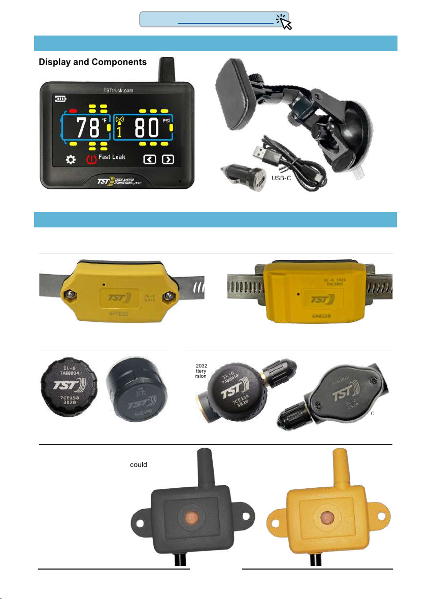
TST-770 SYSTEM COMPONENTS - DISPLAY
Display and Components
SYSTEM COMPATIBLE COMPONENTS*
5” Touch Screen Color Display
USB-C
Cable
Suction
Cup
Mount
Magnetic
Display
Mount
12v Power
Adapter
CR1632
Battery
Version
CR2032
Battery
Version
TST RV & Hybrid Cap Sensors
TST Repeaters
The repeater is an integral component to
your TPMS system.
Failure to install the repeater could
void the warranty coverage.
TST Flow-thru Sensors
Screw-mounted Internal Sensors & Band Slide-on Internal Sensors & Band
TST Internal Sensors
* Beginning with product date code 0119 and after.
Back To TABLE OF CONTENTS

TST-770 WSD Full Line Manual-RevA
© 2021 Truck System Technologies and Pressure Systems International Inc. All Rights Reserved Worldwide.
Page 5
DISPLAY CONTROLS AND INFORMATION
DISPLAY INSTALLATION AND CHARGING
The provided magnetic mount with suction cup base can be used on the windshield, side
window or directly on smooth, nonporous surfaces. Additional magnetic mounts can also
be used with the magnetic base plate on the backside of the display.
To charge the display’s non-replaceable, internal lithium battery, plug the USB power
cord in the provided 12v power adapter and then into the vehicles 12v power port. Plug
the USB-C end of the power cord into the side of the display. The icon indicates
you should charge display, while , , and , indicate battery levels.
When the battery is fully charged the icon goes away.
Note: Displays with date codes earlier than 3321 will remain powered on regardless of
power switch selection while connected to the USB-C charging cable. Date codes of
3321 and later will power down when the off position is selected during charging.
Do not keep a fully charged display plugged in constantly.
Display ICONS
On
Off Power
12v USB-C
Charging
Port
Tire Icon
(not yet coded)
Tire Programmed
(Tire Swap Location screen)
Tire Normal
(after coded)
Tire Alert
(after coded)
ºF / ºC Temperature Unit
PSI/BAR Pressure Unit
Pressure Warning
Temperature Warning
Sensor Low Battery
Repeater Signal
Trailer Icon
(Trailer 1 example)
LCD Color
Touchscreen
Display
Antenna
Red LED alert light
Sensor pairing area
Scan QR Code for
online support and
documentation
Display part number
and revision code
Display production
4-digit date code
(needed for warranty
registration)
Magnetic base
mount plate
Back To TABLE OF CONTENTS
Table of contents
Other TST Automobile Accessories manuals


Popular Automobile Accessories manuals by other brands


ULTIMATE SPEED
ULTIMATE SPEED 279746 Assembly and Safety Advice

SSV Works
SSV Works DF-F65 manual

ULTIMATE SPEED
ULTIMATE SPEED CARBON Assembly and Safety Advice

Witter
Witter F174 Fitting instructions

WeatherTech
WeatherTech No-Drill installation instructions

TAUBENREUTHER
TAUBENREUTHER 1-336050 Installation instruction