TST TM-507 User manual

Wireless Tire Pressure and Temperature
Monitoring System Instrucon Manual
Model #: TM-507
507 Flow-through and Cap Sensors
Thank you for purchasing the TST Tire Pressure Monitoring
System. With minimal care, your new TPMS will
provide reliable service for many years. Please read and
understand the informaon contained within this manual.
Keep this manual for future reference.
TST-Doc-507 Manual-(B)

INDEX
Page 1 - Sensor Features
Page 1 - Display Features
Page 2 - System Components in Kit
Page 3 - Display Controls
Pages 4 - 7 - Programming Sensor Codes Into the Display
- Automac Code Learning (Opon #1)
- Pressure Coding (Opon #2)
- Manual Coding (Opon #3)
Page 8 - Sensor Installaon - Flow-through/Cap
Page 9 - Display Installaon
Page 10 - Display Buons
Page 10 - 12 - Parameter Sengs (Pressure & Temperature)
Pages 13 & 14 - Display Alerts
Page 15 - Other Funcons
Pages 16 & 17 - Replacing the Flow-through Sensor Baery
Page 18 - Replacing the Cap Sensor Baery
Page 19 - Troubleshoong Tips
Pages 20 - 23 - Common Quesons
Page 23 - Sensor Specicaons
Page 24 - Display Specicaons
Page 25 - Repeater
TST-Doc-507 Manual-(B)
More Info

1
Truck System Technologies TST 507 Instructional Manual
SENSOR FEATURES
1. The sensors easily install on the valve stem.
2. Sensors are water resistant.
3. Pressure and temperature data is read every two (2) minutes.
4. Removal of a sensor (0 lbs. pressure) will shut o the sensor
baery.
5. The sensor baeries last approximately one (1) year and are
user replaceable.
6. Tire leaks and high temperatures are detected quickly.
7. Tires can be inated without removing the sensor.
8. Each sensor has a unique, six (6) digit code for programming.
9. One-buon sensor coding feature on display.
10. Sensors feature an an-the design using the included hex
screws (507FT) and outer shell cap with wrench (507 Cap).
DISPLAY FEATURES
1) Easy to read display.
2) Two mounts included.
3) Integrated lithium baery that is rechargeable with provided
cord.
4) Wake-up acvaon of display when in moon.
5) Automac display illuminaon in dark condions.
6) Programable high and low pressure alarm thresholds.
7) Programmable high-temperature alarm.
TST-Doc-507 Manual-(B)

2
Truck System TechnologiesTST 507 Instructional Manual
8) Visual and audible warning alarms when temperature or
pressure exceeds thresholds.
9) Mulple pressure units: PSI, BAR, Kpa and Kgf/cm2.
10) Selectable temperature unit: °C or °F
11) Program up to 22 res.
12) Tire pressure and temperature is displayed simultaneously
for quick viewing of each re.
13) The trailer display can be electronically removed from the
screen when not towing.
14) Push buon programming.
15) A fully charged display will connuously operate 5-7 days on
baery power.
16) Tire temperature and pressure sengs are congured “per
axle.”
Display
Cradle
Suction Cup Mount
Extra “O” rings
Power Adapter
Hard Wire Kit
SYSTEM COMPONENTS IN KIT
TST-Doc-507 Manual-(B)

3
Truck System Technologies TST 507 Instructional Manual
Pressure Unit: BAR, PSI, Kpa or Kgf/cm2, user-selectable.
Temperature unit: C° or F°, user-selectable.
or
Cap WrenchesFT Hex Wrenches
Flow-through Sensors Cap Sensors
DISPLAY CONTROLS
Tire Indicator
Low Sensor Baery
Fast Leakage
High Pressure
Low Pressure
High Temperature
Display Baery
or
TST-Doc-507 Manual-(B)

4
Truck System TechnologiesTST 507 Instructional Manual
PROGRAMMING SENSOR CODES INTO THE DISPLAY
Note: It is recommended to label each sensor rst with the
provided numbering code sckers, similar to the following
paern, before you code the sensors. This allows you to know
which sensor is programmed to which re posion. You can also
write in your own sensor number paern.
AUTOMATIC CODE LEARNING (opon #1)
Note: Code all the sensors to the display BEFORE screwing them
onto the re valve stem unless otherwise noted.
• Turn the display on. You will be on the Main Screen.
• Press and hold the “CODE” buon unl it beeps and then
release it (approx. 6 seconds). You are now in the coding
mode.
• A re icon will ash and all 22 res will be displayed.
“FFF FFF” should also be displayed.
Or use your own paern:
TST-Doc-507 Manual-(B)

5
Truck System Technologies TST 507 Instructional Manual
Note: If the right front re is blinking and does not show all “Fs”
you can delete that factory test sensor code as follows:
Press the “SET” buon unl it beeps (approx. 3 seconds). The dis-
play should now show “FFF FFF.” This display indicates the re po-
sion is NOT coded and will not show on the Main Screen when
out of the coding mode.
• Normally, start coding on the right/passenger side of
the vehicle. This is posion #1 or, in the case of a trailer,
posion #T1.
• Be sure you have your rst sensor ready and keep the
remaining sensors at least two (2) feet away from the
display as to not interfere with the coding procedure.
• Hold your rst sensor to the boom of the display
and quickly press and release the “CODE” buon. The
display’s red LED should light and it should beep once.
A six (6) digit unique code should now appear on your
screen, replacing the “FFF FFF.”
Note: If a double beep is heard and the “FFF FFF” does not
change, try quickly pushing the “CODE” buon once again. This
may have to be done a few mes for the code to appear. If the
sensor does not code, check the baery voltage, be sure other
sensors are not close to the coding sensor, be sure the sensor
is touching the display, and be sure you are quickly pushing and
releasing the “CODE” buon. Call Tech Support at 770-889-9102
if none of the above works.
• Once coded, use the (+) or (-) buons to navigate to the
next re posion you want to code a sensor to.
• Again, put sensor #2 up to the boom of the display and
quickly press and release the “CODE” buon to capture
the sensor code. The “FFF FFF” should change to a new
unique code.
TST-Doc-507 Manual-(B)

6
Truck System TechnologiesTST 507 Instructional Manual
• Connue this process unl all your sensors are coded in
the correct re posions.
• Finally, press and release the “MODE” buon to go back
to the Main Screen. You should now see only the res
you coded. You have now completed the automac
sensor code set-up.
Note: When in the coding mode, the display will me-out within
approximately one (1) minute if no buons are pushed. At that
point, you will have to again hold the “CODE” buon down unl
it beeps and start the coding process again.
Note: Be sure the sensor being coded is at least 2 feet away from
the other sensors.
PRESSURE CODING (opon #2)
• Be sure your display is ON and it is showing the Main
Screen.
• Be sure your sensors are numbered. Screw the sensors
partly onto each valve stem in the order you numbered
them. Do NOT screw them down far enough to hear air
hissing out.
• Hold the “SET” buon down unl you hear a second
beep and then release.
• Navigate to the re icon you want to code that sensor to.
• Stand by that re and screw the sensor all the way down
to seat it.
TST-Doc-507 Manual-(B)

7
Truck System Technologies TST 507 Instructional Manual
• The sensor will immediately transmit its six digit code to
the display and it will be shown.
• Physically move to the next re posion you want to
code.
• Using the (+) or (-) buon, navigate to the re on the
display you are standing at.
• Again, nish screwing that sensor down to seat it. That
code will now appear on the display.
• Connue this procedure unl you have coded all the
sensor posions.
• Finally, press the “SET” buon unl it beeps to save all
the sensor codes in the display.
MANUAL CODING (opon #3)
Note: This method is mainly used to program sensor codes from
an old display to a new display if you do not have the sensors
available.
• Be sure your display is ON and it is showing the main
screen.
• Hold the “SET” buon down unl it beeps and release
(approx. 3 seconds).
• The rst “F” should be blinking (if no code was entered
previously). Use the (+) or (-) buons to change the rst
digit to the proper unit.
• Press and release the “MODE” buon to move to the
next digit posion. Again, use the (+) or (-) buons to
change that digit.
• Connue this process unl all six (6) of the digits are
properly set.
TST-Doc-507 Manual-(B)
8
Truck System TechnologiesTST 507 Instructional Manual
• To move to another re posion, quickly press and
release the “SET” buon.
• When done, press and hold the “SET” buon unl it
beeps to save the entries.
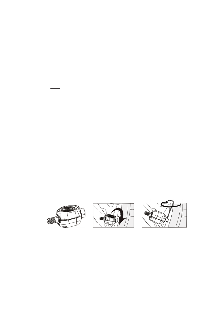
SENSOR INSTALLATION - Flow-through Sensor
• Be sure the an-the allen set screw at the sensor base
is not screwed in as to impede screwing the sensor onto
the valve stem.
• Screw the correctly marked sensor onto the valve stem
for that re posion. Tighten the sensor unl the air
stops leaking and the sensor booms-out on the valve
stem. Give it a slight twist to seat it. Do Not Over-ghten!
• Using the provided small allen wrench, ghten the set
screw onto the valve stem. This will prevent the sensor
from being removed. If necessary, you can put the screw
into the second screw hole to allow access by the allen
wrench if your rim is in the way. Keep the wrench in a
safe place for future use.
• You can now inate or deate the re through the 507FT
sensor without removing it.
SENSOR INSTALLATION - Cap Sensor
• Place the provided wrench around the sensor. You must
use the wrench to put the sensor on or take it o the
valve stem.
• Screw the correctly marked sensor onto the valve stem
for that re posion. Tighten the sensor unl the air
TST-Doc-507 Manual-(B)

9
Truck System Technologies TST 507 Instructional Manual
stops leaking and the sensor booms-out on the valve
stem. Give it a slight twist to seat it. Do Not Over-ghten!
• Keep the wrench in a safe place for future use.
• To inate or deate the re, you must remove the 507
cap sensor.
DISPLAY INSTALLATION
• There are two display mounts that come with the kit: A
sucon cup mount and a dash mount. Double-sided tape
is provided for axing the dash mount display holder.
• The sucon cup mount can be used on the windshield,
side window or directly on a smooth dash. Snap the
mount into the back tabs on the display to use.
• Plug the power cord into the vehicle’s cigaree lighter/
power port and then into the side of the display to charge
the internal lithium baery. Charge the display for four
(4) hours the rst me.
• An oponal hard wire cord is provided if you choose to
wire the display into your vehicle’s ignion switch. In this
case, the display will automacally come on when the
ignion is on.
TST-Doc-507 Manual-(B)

10
Truck System TechnologiesTST 507 Instructional Manual
DISPLAY BUTTONS
• There are ve (5) programming buons located across
the top of the display. They are: “SET,” (+), (-), “MODE”
and “CODE.”
• The power slide switch is located on the right side of the
display. Slide it up to turn on the display. Slide it down to
turn o the display.
NOTE: The side power switch will not turn o the display
when constant power is applied to the unit either by
the cigaree lighter/power cord or the hard wire kit.
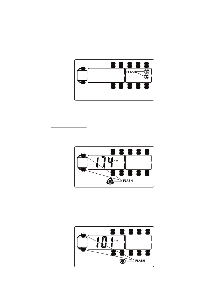
PARAMETER SETTINGS (Seng the sensor alarms)
NOTE: The factory default sengs are:
Pressure Unit: PSI Temperature units: °C
High Pressure: 175 lbs. High Temperature: 70°C (158° F)
Low Pressure: 100 Lbs.
• Be sure your display is ON and it is showing the Main
Screen.
• Press and hold the “MODE” buon unl the display
beeps (approx. 6 seconds).
• You should see “PSI” on the screen. If not, push and
release the (+) buon to scroll through the pressure units
unl “PSI” appears.
TST-Doc-507 Manual-(B)
11
Truck System Technologies TST 507 Instructional Manual
• Press and release the “MODE” buon (do not hold it
down). “C” for Cengrade (Celsius) will appear on the
screen. For Fahrenheit, press and release the (+) buon,
unless you want the display to read temperature in
Cengrade (Celsius). An “F” will appear.
• Press and release the “MODE” buon. The rst axle (steer
axle) on the truck cab will appear and will blink showing
the high-pressure alarm seng. If you are pung sensors
on this axle, set the pressure alarm to 20-25% above your
normal re pressure for those res.
• Press and release the “MODE” buon. The low pressure
alarm seng will appear. Set this at 10% below the
normal re pressure for this axle.
High Pressure-Front Axle
Low Pressure-Front Axle
TST-Doc-507 Manual-(B)

12
Truck System TechnologiesTST 507 Instructional Manual
NOTE: If your normal re pressures are below 100 lbs., you must
rst set the low-pressure alarm and then go back around to the
same axle (by clicking the “MODE” buon) and set the high
pressure. This must be done for any axle with pressures less than
100 lbs.
• Press and release the “MODE” buon. The next axle in
sequence will blink and the high-pressure alarm will be
displayed. If you have sensors here, set the high-pressure
alarm and press and release the “MODE” buon. Set the
low-pressure alarm for that axle.
• Connue to set the high and low pressures for each
axle.
• When you get to the Trailer Secon of the display, all the
res will ash. You can now set all the trailer axle high
and low pressures as one group. Set the high-pressure
alarm, press and release the “MODE” buon and set the
low-pressure alarm.
High Pressure-2nd Axle Low Pressure-2nd Axle
High Pressure-Trailer Low Pressure-Trailer
TST-Doc-507 Manual-(B)

13
Truck System Technologies TST 507 Instructional Manual
• Press and release the “MODE” buon once again and the
temperature icon appears and the default temperature
seng of 158° will display. Typically, do not change this
seng unless you have a special circumstance.
• Finally…IMPORTANT…Push and release the “SET” buon
to save all your parameter sengs in the display.
DISPLAY ALERTS
Out of Parameter Alert
The 507FT and Cap sensors send the re pressure and temperature
readings to the display every two (2) minutes. If a re is outside
the parameters that were set, the audible alarm will sound and
the red LED light will immediately ash. The audible alarm can be
silenced for a short while by pushing any of the ve buons on
the top of the display. The red warning light will connue to ash
unl the pressure or temperature issue is resolved and brought
back into your pre-set levels.
Fast Leak Alert
When a fast re leak is detected, the sensor will send that data
immediately to the display. You will see the problem re ash on
the display, the corresponding icon will be seen at the boom of
the screen and the pressure and temperature read-outs will ash.
You will also get an audible alarm. Again, you can press any of the
ve top buons to silence the alarm for a short while. The display
will connue to ash and alarm unl the problem is corrected.
TST-Doc-507 Manual-(B)

14
Truck System TechnologiesTST 507 Instructional Manual
Sensor Low Baery Alert
The sensor low baery indicator will display when the CR1632
baery is at the end of its life. The re aected will ash along
with the pressure and temperature read-out and the low baery
symbol in the lower le corner of the display. Replace with a new
baery as soon as possible.
NOTE: This low baery alert will display for only a short me unl
the baery is exhausted. If you do not have the display on of-
ten, the indicator signal will be sent, but not shown on the dis-
play since it was o. If your sensor is not reporng to the display,
check the baery voltage. If it is below 2.75 volts (normally 3+
volts), you will have to change the sensor baery.
Fast Leak Alert
Low Sensor Battery Alert
TST-Doc-507 Manual-(B)

15
Truck System Technologies TST 507 Instructional Manual
OTHER FUNCTIONS
Normal Display Scrolling
The display will automacally scroll/cycle through the displayed
res one by one. Each re will be displayed for approximately
5-6 seconds. You can manually cycle through the displayed res
by pushing the (+) or (-) buons on the display. The display will
show the re you choose for approximately 10 seconds before
connuing to cycle.
Backlighng and Moon Detecon
The display is equipped with a light-sensor and a moon-sensor.
The backlight will turn on when the vehicle is in moon and there
is lile ambient light. If the vehicle has stopped for a while and
the display is on the internal baery, the display will “go to sleep”
unl the vehicle resumes moon. To shut the light-sensor o,
press the (+) buon for approximately 4 seconds.
Disconnecng and Reconnecng a Towed Vehicle
When a towed vehicle is displayed on the screen and you want to
temporarily remove it (example: leaving a trailer at a campground),
press and hold the “MODE” and (-) buons simultaneously unl
the trailer secon of the display disappears. The sensors on the
trailer will not be read. To add the trailer secon back on to the
display again, push the “MODE” and (-) buons at the same me
unl the towed vehicle reappears.
Charging the Display
The display is powered by a non-replaceable, lithium-ion baery.
A baery level indicator is located on the front, lower right side of
the display. When the indicator shows one bar, it is recommended
you charge the display as soon as possible to avoid disrupon
when in use. It will take approximately four (4) hours to fully
charge. Display run me is 5-7 days on a full charge.
TST-Doc-507 Manual-(B)

16
Truck System TechnologiesTST 507 Instructional Manual
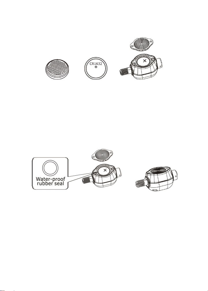
REPLACING THE FLOW-THROUGH SENSOR BATTERY
(CR1632)
•Remove the sensor from the re valve stem.
•Use a jeweler’s Phillip’s screwdriver to remove the two
screws from the baery cover on the side of the sensor.
The (+) side of the baery can now be seen.
•Remove the CR1632 baery and check that the metal
contact points in the sensor are not corroded. To clean
the contact points, use a pencil eraser and lightly rub the
two metal baery contacts in the sensor.
TST-Doc-507 Manual-(B)
17
Truck System Technologies TST 507 Instructional Manual
• Install a new baery. Be sure the (+) (posive) side is
facing out.
NOTE: It is recommended that you check the voltage of the new
baery before installaon. It should read 3+ volts when new. Do
not install if the baery reads less than 3 volts.
• Check the “O” ring that surrounds the baery
compartment. This is the waterproof seal. Replace if
old or damaged. Addional “O” rings are provided in
your 507FT kit or can be purchased from TST by calling
770-889-9102.
• Aer a new baery installaon, replace the baery
compartment cover and snuggly ghten the two screws.
Do not over-ghten.
• Screw the sensor on to the correct re posion.
• Tighten the allen screw onto the valve stem.
NOTE: Changing the baery in the sensor does NOT aect the
sensor programming in the display. You will not have to reprogram
the sensor into the display.
TST-Doc-507 Manual-(B)
18
Truck System TechnologiesTST 507 Instructional Manual
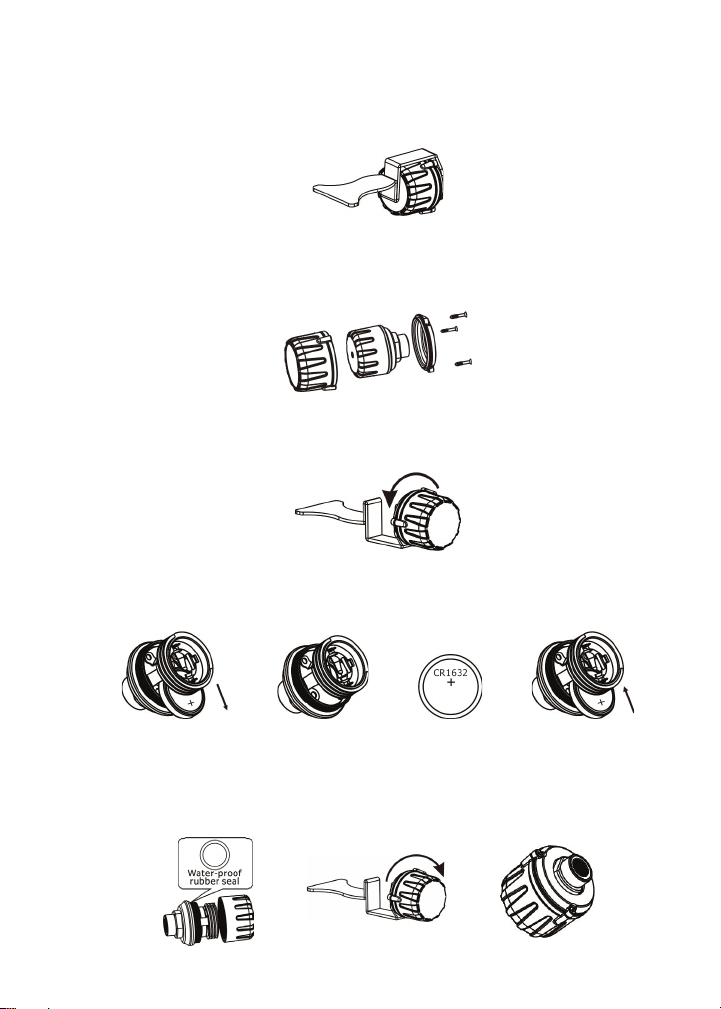
REPLACING THE CAP SENSOR BATTERY (CR1632)
• Remove the sensor from the re valve stem.
• Use a jeweler’s Phillip’s screwdriver to remove the three
screws at the base of the sensor. This will separate the
an-the housing.
• Use the installaon tool to hold the base of the inner
sensor and screw o the cap.
• Slide the baery out of the cage sideways. Note that the
(+) side is up. Replace with a new baery that is 3+ volts.
• At this me check the “O” ring at the base of the threads.
Be sure it is in place. If it is worn or broken, replace it.
Screw the cap back on, replace the two halves of the an-
the housing and replace the three Phillip-head screws.
TST-Doc-507 Manual-(B)
Other manuals for TM-507
2
Table of contents
Other TST Automobile Accessories manuals


