tsw TEPACK TPS 400 User manual

TPS 400
MECHANICAL OPERATING MANUAL
VOLUME II


MECHANICAL OPERATING MANUAL
TÉCNICAS DE INGENIERIA DE ENVASES S.L. 3
TPS 400
MULTILANE SACHET MACHINE
MECHANICAL OPERATING MANUAL
CUSTOMER: ORIENT BIO TECH
SERIAL NR : 0318003
TEPACK reserves the right of changing or modifying without no ce the content of this
publica on.
Manual wri en in accordance with the direc ve 89/392/CE and successive
modifi ca ons.
Made by the Technical / Documenta on Department of TEPACK.
Last date of prin ng: 02-2020
VOLUME II


MECHANICAL OPERATING MANUAL
VOLUME II
TÉCNICAS DE INGENIERIA DE ENVASES S.L. 5
TABLE OF CONTENTS
1.- INTRODUCTION ...........................................................................................................7
1.1.- Main Features. .....................................................................................................7
1.1.1.- Formats range. .............................................................................................7
1.1.2.- Format drawing. ...........................................................................................8
1.2.- Main features. ......................................................................................................9
1.2.1.- Unreeler .....................................................................................................11
1.2.2.-Reel alignment. ...........................................................................................11
1.2.3.- Splicing table ..............................................................................................12
1.2.4.- Accumulator. ..............................................................................................12
1.2.5- Printer support. ...........................................................................................13
1.2.6.- Film brake. ..................................................................................................13
1.2.7.- Spot photocell. ...........................................................................................14
1.2.8.-Longitudinal cu ng. ...................................................................................14
1.2.9.- Format. .......................................................................................................15
1.2.10.- Ver cal seal. .............................................................................................15
1.2.11.- Horizontal seal (Driving group) ................................................................16
1.2.12.- Regula on plate .......................................................................................16
1.2.13.- Tear notch. ...............................................................................................17
1.2.14.- Shears. ......................................................................................................17
1.2.15.- Cut die. .....................................................................................................18
1.2.16.- S ck guide ................................................................................................18
1.2.17.- Electrical board. .......................................................................................19
1.2.18.-Display board. ...........................................................................................19
2.- INSTRUCTIONS OF USE. ............................................................................................20
2.1.- Prepara on / Disposi on to work. .....................................................................20
2.1.1.- Layout for the beginning of a produc on cycle. .........................................20
2.1.2.-Sequences of a Normal Produc on Cycle. ..................................................20
2.1.3.- How to Stop the Produc on Process..........................................................20
2.1.4.- Ini al Sequences a er a Synchronized Stop. .............................................20
2.2.- How to act in an Emergency Situa on. ..............................................................21
2.2.1.- How to stop the Produc on Cycle in case of Emergency. ..........................21
2.2.2.- How to Restore the Produc on Process a er an Emergency. ...................21
2.3.- How to act in an Alarm Situa on. ......................................................................21
2.3.1.- How to Restore the Produc on Process a er an Alarm. ...........................22
3.- PROCEDURES .............................................................................................................23
3.2.- Adjustments. ......................................................................................................24
3.2.1.- Inlet pneuma cal maintenance group. ......................................................25
3.2.2.- Reel loading of heatsealable fi lm. ..............................................................26
3.2.3.- Film passing. ...............................................................................................27
3.2.4.- Reels Replacement. ....................................................................................28

MECHANICAL OPERATING MANUAL
VOLUME II
TÉCNICAS DE INGENIERIA DE ENVASES S.L. 6
3.2.5.- Film brake regula on .................................................................................29
3.2.6.- Centering photocell regula on. ................................................................29
3.2.7.- Cu ng group regula on ...........................................................................30
3.2.8.- Film entry. ..................................................................................................31
3.2.9.- S ck forming. .............................................................................................32
3.2.10.- Ver cal sealing. ........................................................................................33
3.2.11.- Horizontal sealing. ....................................................................................34
3.2.12.- Change of the pulling mechanical length .................................................35
3.3.- Replacements. ...................................................................................................36
3.3.1.- Replacement of a longitudinal knife. ........................................................37
3.3.2.- Replacement of a resistance or probe from the front ver cal Seal Group. 38
3.3.3.- Replacement of a resistance or a probe, rear horizontal sealing group. ....39
VOLUMETRIC FILLER 42
4.- INTRODUCTION .........................................................................................................43
4.1.- Layout. ...............................................................................................................43
4.2.- Components. .....................................................................................................44
4.2.1.- Hopper. ......................................................................................................45
4.2.2.- Level detector ............................................................................................45
4.2.3.- Product inlet funnel ...................................................................................46
4.2.4.- Pre-hopper .................................................................................................46
4.2.5.- Prehopper ac va on. .................................................................................47
4.2.6.- Cups ac va on. ..........................................................................................47
4.2.7.- Cups. ..........................................................................................................48
4.2.8.- Product collec on tray ...............................................................................48
4.2.9.- Dose adjustment ........................................................................................49
5.- PROCEDURES. ............................................................................................................50
5.1.- Working principle ...............................................................................................50
5.2.- Adjustments and replacements. ........................................................................51
5.2.1.- Dose adjustment. .......................................................................................52
6- PERIODICAL MAINTENANCE OF THE MACHINE..........................................................54
6.1.- Standard maintenance .......................................................................................54
6.2.- Periodical cleaning .............................................................................................54
6.2.1.- Cleaning of the volumetric fi ller .................................................................55

MECHANICAL OPERATING MANUAL
VOLUME II
TÉCNICAS DE INGENIERIA DE ENVASES S.L. 7
1.- INTRODUCTION
1.1.- Main Features.
The ver cal mul lane sachet packing machines have been prepared for the mul ple
forming and fi lling (6, 8, 10,… depending on the format) star ng from a single reel of heat
sealable fi lm.
These machines are specially designed to fi ll any kind of liquid, pasty, powder or granulated
product in s ck sachets made of heat sealable materials and complexes, by mul ple fi lling
systems.
On the study there have been taken into account the smallest details ge ng, apart from an
easy use, a minimum maintenance. Its concep on is simple, strong and versa le, everything
within excellent dimensions.
Before its launching there has been tested its high performance, being subjected to the
hardest tests in all format range.
1.1.1.- Formats range.
The mul lane packing machine is designed to fi ll any kind of product into 3 side sealed
sachets. The range of formats made by this machine is very varied, depending on the product
to be fi lled and the kind of fi lm to be used.

MECHANICAL OPERATING MANUAL
VOLUME II
TÉCNICAS DE INGENIERIA DE ENVASES S.L. 8
Fig. 1: Format drawing.
1.1.2.- Format drawing.
Ø75
Ø MAXIMUM 500
400
10
5
55
130
5
10
5
22,5
VISIBLE FIN
VISIBLE REAR PANEL
INSIDE FIN FLAP
COVERED BY FIN SEAL
VISIBLE REAR PANEL
FRONT PANEL
100
45
130
22,5
VISIBLE REAR PANEL
VISIBLE FIN
VISIBLE REAR PANEL
45
130
VISIBLE FIN
VISIBLE REAR PANEL
INSIDE FIN FLAP
COVERED BY FIN SEAL
VISIBLE REAR PANEL
FRONT PANEL
VISIBLE FIN
VISIBLE REAR PANEL
INSIDE FIN FLAP
COVERED BY FIN SEAL
VISIBLE REAR PANEL
FRONT PANEL
VISIBLE FIN
VISIBLE REAR PANEL
INSIDE FIN FLAP
COVERED BY FIN SEAL
VISIBLE REAR PANEL
FRONT PANEL
VISIBLE FIN
VISIBLE REAR PANEL
INSIDE FIN FLAP
COVERED BY FIN SEAL
VISIBLE REAR PANEL
FRONT PANEL
VISIBLE FIN
VISIBLE REAR PANEL
INSIDE FIN FLAP
COVERED BY FIN SEAL
VISIBLE REAR PANEL
FRONT PANEL
VISIBLE FIN
VISIBLE REAR PANEL
INSIDE FIN FLAP
COVERED BY FIN SEAL
VISIBLE REAR PANEL
FRONT PANEL
VISIBLE FIN
VISIBLE REAR PANEL
INSIDE FIN FLAP
COVERED BY FIN SEAL
VISIBLE REAR PANEL
FRONT PANEL
VISIBLE FIN
VISIBLE REAR PANEL
INSIDE FIN FLAP
COVERED BY FIN SEAL
VISIBLE REAR PANEL
FRONT PANEL
MECHANICAL OPERATING MANUAL
VOLUME II
TÉCNICAS DE INGENIERIA DE ENVASES S.L. 9
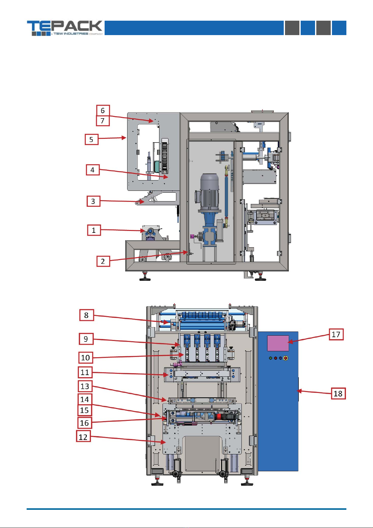
1.2.- Main features.
Below there are illustrated, in Fig. 2, the diff erent parts of a ver cal sachet machine. A general
schema that will let the operator to manage easily during the diff erent opera onal phases.
Fig. 2: Machine components.

MECHANICAL OPERATING MANUAL
VOLUME II
TÉCNICAS DE INGENIERIA DE ENVASES S.L. 10
1Unreeler
2Reel alignment
3Splicing table
4Accumulator
5Printer
6Film brake
7Spot photocell
8Longitudinal cu ng
9Format
10 Ver cal sealing
11 Horizontal sealing and pulling
12 Regula on plate
13 Tear notch
14 Shears
15 Cu ng die
16 S cks guide
17 Electrical board
18 Driving group
19 Display
Table 1: Machine components.

MECHANICAL OPERATING MANUAL
VOLUME II
TÉCNICAS DE INGENIERIA DE ENVASES S.L. 11
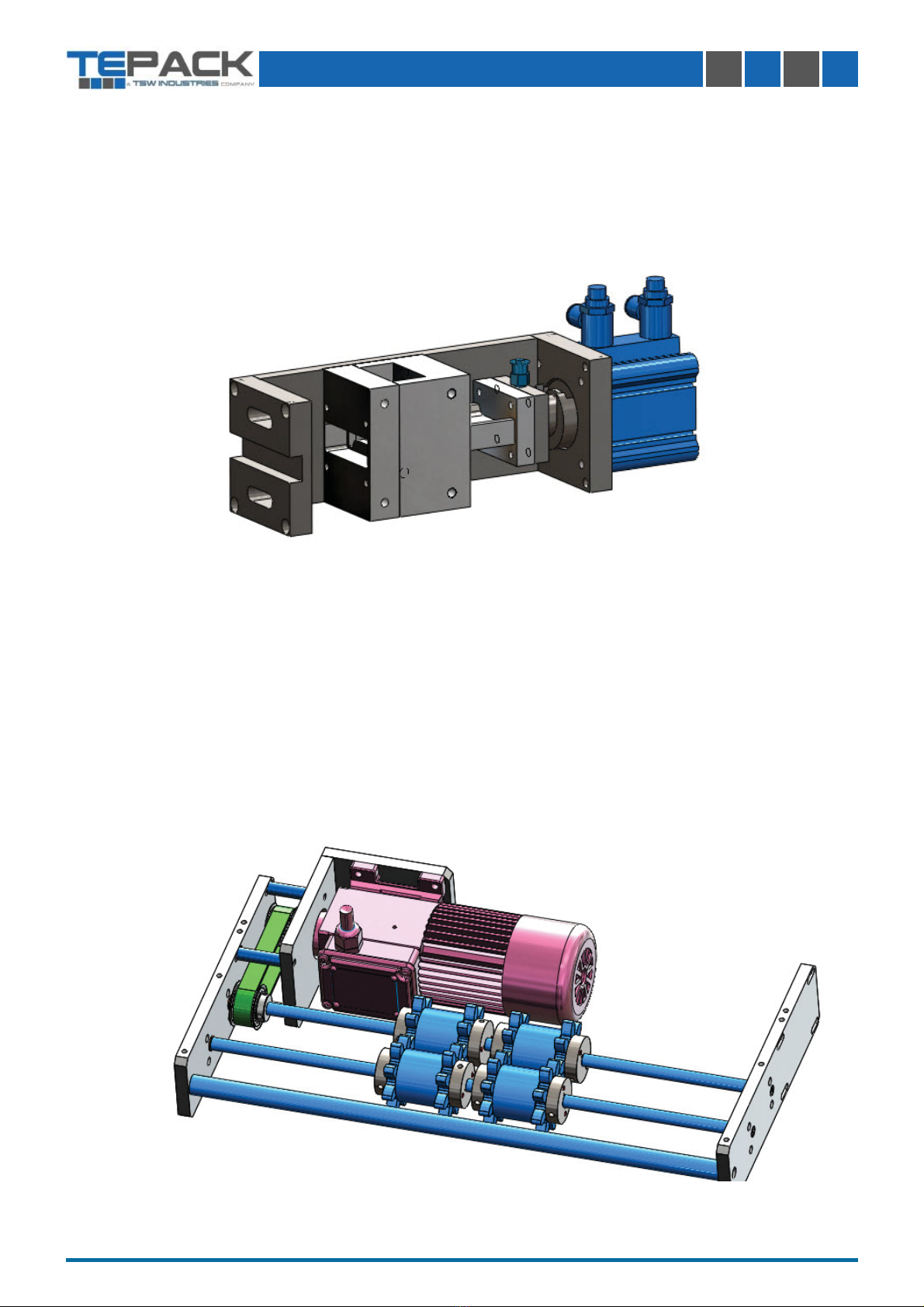
1.2.2.-Reel alignment.
The fi lm, either it is not well placed on the reel holder sha or due to a bad status of the
reel, does not get in the correct posi on to form and create the s ck. The reel alignment
group, through a linear motor (Fig. 4 (a)) that moves the unreeler group (Fig. 4 (b)), and the-
refore the reel to the le or to the right, permits, through the touch screen, to move this reel
manually to the correct posi on.
Fig. 4: Reel alignment.
Fig. 3: Unreeler
1.2.1.- Unreeler
The unreeler group has the task to unroll the reels of heatsealable fi lm and to accompany
this fi lm by maintaining the tension all the me, depending on the machine’s fi lm requirements.
This group consists of:
- Reel holder sha . (Fig. 3 (a))
- Frein unreeler. (Fig. 3 (b))
Reel is placed on the expansible sha (Fig. 3 (a)), which permits this reel to be securely
fastened on it. Depending on the fi lm needs, the unreeler motor (Fig. 3 (b)) turns this sha ,
faster or slower, to unroll the fi lm.
MECHANICAL OPERATING MANUAL
VOLUME II
TÉCNICAS DE INGENIERIA DE ENVASES S.L. 12
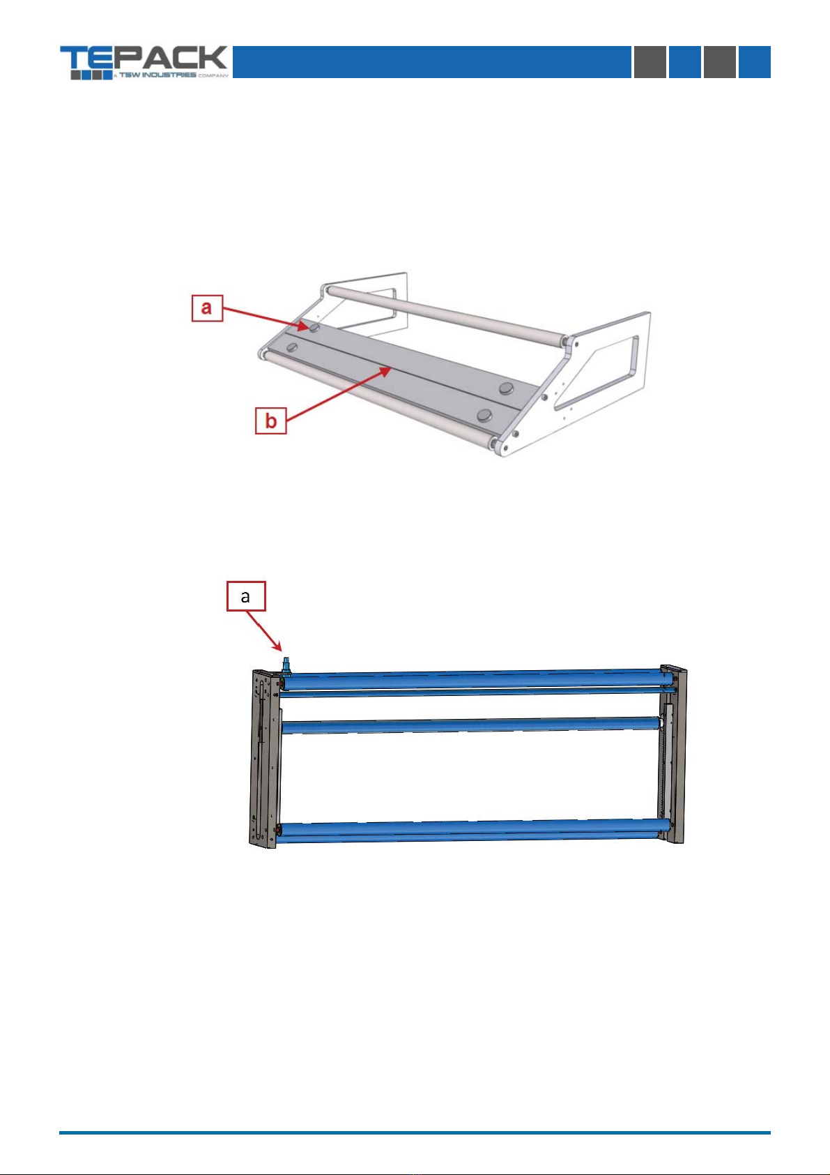
1.2.3.- Splicing table
The splicing table is a group used to change the reel in an easy and quick way. This group,
as its name says, permits to splice easily a reel which is going to be fi nished to a new one. It
has some magnets (Fig. 5 (a)) wich maintain the fi lm in the correct posi on, one longitudinal
incission (Fig. 5 (b)) makes easier the cu ng of the fi lm.
Fig. 5: Splicing table
1.2.4.- Accumulator.
The accumulator is a group that works directly with the unwinder group and serves as the
fi lm lung, as well as to keep the tension on it.
Fig. 6: Accumulator
In this group there is a sensor that enables to control the fi lm status all the me.
This sensor (Fig. 6 (a)) stops the machine when it detects that the reel has fi nished. When
there is a stretching excess caused by any fault, this sensor acts and regulates this fault. It
also regulates the accumulator feeding, which lets the fi lm to be fed during the produc on
process.
TÉCNICAS DE INGENIERIA DE ENVASES S.L. 13
MECHANICAL OPERATING MANUAL
VOLUME II
1.2.5- Printer support.
This set is to support the printer.
It also has an accumulator that makes the fi lm to be ght to get a proper prin ng.
Fig. 7: Printer support.
1.2.6.- Film brake.
The ver cal sachet machine TPV is an intermi ent machine, so the fi lm is pulled by cycles.
It means that fi lm must not be loosen, this is the reason there is a fi lm brake group. This group
holds the fi lm while the pulling group is open, when it closes fi lm is released to be able to pull
it for making a new cycle.
Fig. 7: Film brake.

TÉCNICAS DE INGENIERIA DE ENVASES S.L. 14
MECHANICAL OPERATING MANUAL
VOLUME II
1.2.7.- Spot photocell.
This group detects, through a mono-croma c photocell, (Fig. 8 (a)) a mark which is located
in a concrete zone of the printed reel, avoiding to have the same sachet length.
Fig. 8: Spot photocell.
1.2.8.-Longitudinal cu ng.
The func on of this group is to cut the fi lm longitudinally at the necessary size to make the
sachet.
This group has been previously adjusted by a specialized technician in such a way that the
distance between knives is the exact size of the necessary fi lm width corresponding to the
sachet format before forming it (Fig. 9 (a)).
Fig. 10: Longitudinal cu ng.
MECHANICAL OPERATING MANUAL
VOLUME II
TÉCNICAS DE INGENIERIA DE ENVASES S.L. 15
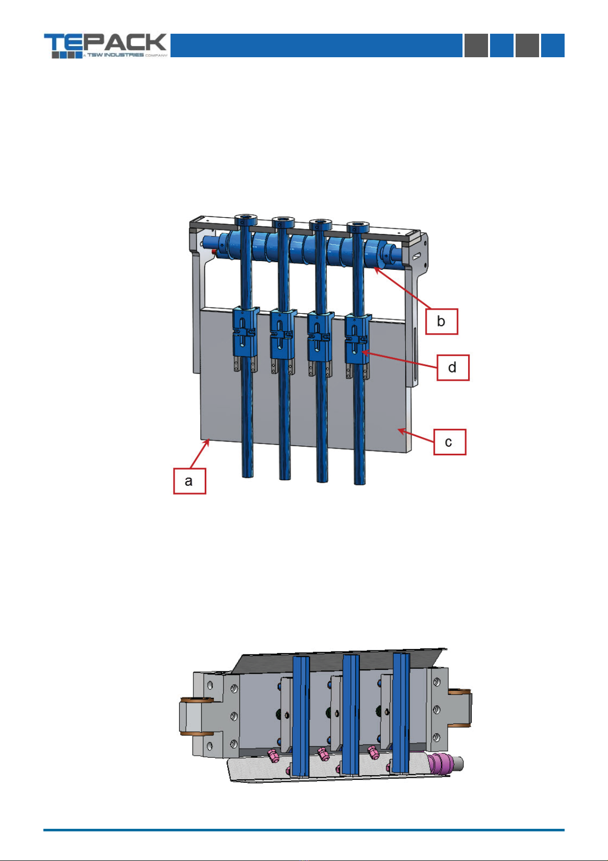
Fig. 10: Format.
1.2.9.- Format.
This group is composed by
- Format plate (Fig. 10 (a)) :
- Forming rollers (Fig. 10 (b))
- Tubes (Fig. 10 (c))
- Former. (Fig. 10 (d))
The func on of this group is to form the sachet for its later sealing.
1.2.10.- Ver cal seal.
This is a group formed by independend ver cal sealers, many as number of lanes the
machine has. Its func on is to seal the sachet ver cally.
Fig. 11: Ver cal seal.

MECHANICAL OPERATING MANUAL
VOLUME II
TÉCNICAS DE INGENIERIA DE ENVASES S.L. 16
1.2.11.- Horizontal seal (Driving group)
The horizontal sealer has a double func on; it makes the s cks horizontal sealing and also
pulls them.
Fig. 12: Horizontal seal
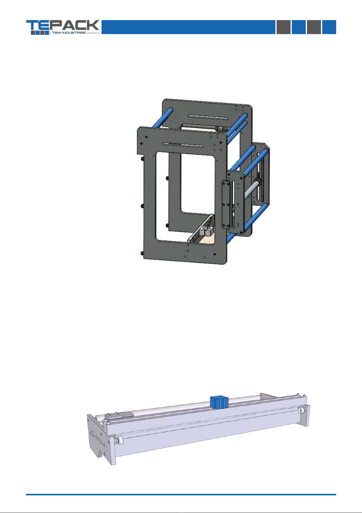
1.2.12.- Regula on plate
The func on of this plate, driven by two linear motors, is to regulate at the same me the
groups installed on it.
Fig. 13: Regula on plate

TÉCNICAS DE INGENIERIA DE ENVASES S.L. 17
MECHANICAL OPERATING MANUAL
VOLUME II
1.2.14.- Shears.
This group is composed of:
- Servomotor. (Fig. 14 (a))
-Knife. (Fig. 14 (b))
- Counter knife. (Fig. 14 (c))
- Cam. (Fig. 14 (d))
The func on of this group is to cut the s cks horizontally, separa ng the sachets with a
straight cut.
1.2.13.- Tear notch.
Op onal group; this is to make the necessary cu ngs on the s ck to open it easily.
Fig. 23: Tear notch.
TÉCNICAS DE INGENIERIA DE ENVASES S.L. 18
MECHANICAL OPERATING MANUAL
VOLUME II
1.2.15.- Cut die.
This group cuts, through a cu ng die, the upper part of the sachets, giving them a special
shape.
Fig. 17: Cut die.
1.2.16.- S ck guide
This set of parts is to ghten and guide the s cks in order they can be properly die-cut.
Fig. 16: S ck guide.

MECHANICAL OPERATING MANUAL
VOLUME II
TÉCNICAS DE INGENIERIA DE ENVASES S.L. 19
1.2.17.- Electrical board.
The necessary electrical components for the correct working of the machine are located
inside an electrical board which is wired up according to guidelines. The standard board is
included on the machine, but there is also the possibility to have an external board (op onal)
in case it is necessary.
Fig. 19: Display.
Fig. 18: Electrical board.
1.2.18.-Display board.
The machine has a display board where there are located the controls and the touch screen.
This board has a mobile arm which permits an easy handling of the machine by the operator.

MECHANICAL OPERATING MANUAL
VOLUME II
TÉCNICAS DE INGENIERIA DE ENVASES S.L. 20
2.- INSTRUCTIONS OF USE.
2.1.- Prepara on / Disposi on to work.
2.1.1.- Layout for the beginning of a produc on cycle.
Take proper precau ons for the work site to be in condi ons to make it
possible to reach easily and safely any part of the installa on.
- Check if the products being treated match those of the planned format.
- Check that the amount of materials for the packing is suffi cient for the planned produc on
period.
- Place the product in the fi lling group.
- Place the fi lm reels and pass the fi lm through the unwinder group to the pulling group.
- Supply power to the machine by means of the main switch located on the control panel.
- Make sure that all the protec on doors are securely closed.
2.1.2.-Sequences of a Normal Produc on Cycle.
To begin a normal produc on cycle, it has to be checked that the machine is ready to
begin the cycle. Reset the installa on by pressing the Reset pushbu on (in case there
is an alarm or emergency stop in the memory) and then press the Start pushbu on in
order to begin a Produc on Process. They are both located on the control panel.
Before beginning produc on, check that the machine has been forma ed properly.
With the aim of reaching the minimum temperature required in the sealers for their
correct opera on at the beginning of produc on, it is convenient to input power into
the machine and connect the sealers a few minutes prior to beginning produc on.
2.1.3.- How to Stop the Produc on Process.
The only correct procedure to stop the installa on is to press the STOP pushbu on
(Synchronized Stop) located on the Control Board. In this case, the machine does not
stop immediately, but it will do it when the machine’s Stop phase is reached.
2.1.4.- Ini al Sequences a er a Synchronized Stop.
In case the normal produc ve cycle has been stopped by pressing the Stop
pushbu on and produc on must be resumed, the Reset and the Start Pushbu ons
must be pushed in order to begin the Produc on process again. They are located on
the Control Panel.
Other manuals for TEPACK TPS 400
1
Table of contents
Other tsw Industrial Equipment manuals

Popular Industrial Equipment manuals by other brands


Dorner
Dorner 3200 Series Installation, maintenance & parts manual

Kendrion
Kendrion INTORQ BFK457 Translation of the original operating instructions

Danfoss
Danfoss AKS 41 instructions

Eastwood
Eastwood HOTCOAT 33273 instructions

Bastian Solutions
Bastian Solutions Shoe Sorter Installation and maintenance manual

WIKA
WIKA TR12 Series operating instructions