TubeOhm De-Generator User manual

Now that all components are soldered, chec ed and hopefully cleaned, the last step
comes.
The next step is the assembly of the single components on the motherboard and the
adjustment of motherboard and filterboard. We now have the following components:
CPU Board Filterboard
Motherboard
Pannelboard
2

Now we will build the de-generator first of all together
That's what we need:
Abstandshalter/spacer
7x5mm spacer Female/male M3
7x30 mm spacer Male /male M3
6x9mm spacer Female /male M3
2x20 Pol cable CPU to Pannelboard 2x 20 Pol cable /80 mm
1x6 Pol cable Volume Motherboard to Pannelboard Volumen cable /80mm
1x2 Pol cable Motherboard to Pannel
Board
Mic cable
2x10 pol Connector for flat ribbon
cable
4 units CPU/Panelboard
2x3 pol Connector for flat ribbon
cable
2Units volume
Cable assembly:
We need 2x20 pin for the connection of the CPU board with the Pannel Board !
And a 2x6 pole cable for the volume potentiometer.
**** CPU cables and volume cables are supplied in PCB it and complete it.
3

Here a view how the spacers have to
be screwed together with the PCBs.
The 5mm spacers come down, then
the motherboard,
then the 30 mm spacer, then the
panel board. The panelboard is
screwed with 9mm spacers.
At the 5mm and the 9mm spacers the
case will be screwed later.
Here in the picture the positions of the spacers
Installing the ilterboard
First the filterboard is put on the filterboard position.
K11 , the connector for the power switch on the motherboard must of course be short-
circuited or already connected to the ON/OFF switch. Then you can connect the
motherboard to the 12 Volt power supply.
The plug contacts are plugged into the soc ets - then chec if the plugs are all in the right
position - and not next to them.
Then push the filterboard into the soc ets correctly!
4

Here again a picture where the individual tensions lie.
Rot / red = (plus) 8Volt >>> 7,5...8,5 is OK
Grün / green = (minus)-8Volt >>> -7,5...8,2 is OK
Now the voltages on the filter board can be chec ed.
If all voltages are correct, the de-generator is switched off again and the filter board is
pulled out of the slot. Then it can be equipped with the ICs.
5

Installing the CPU Board
Now the CPU board can be plugged into the CPU board position.
Pay attention also with the CPU board to the fact that all plugs are correct in the soc ets!
6

The 2x 20 pin connecting cables are connected to the CPU board.
1:) 2x 20 pin cable from CPU Board to Pannel Board
2:) Mic Cable
3:) Volume cable
And then the CPU board is put on the motherboard.
See picture - all cables have to be plugged in this way.
Connection of the volume cable. Plug and soc et are mar ed !
7

Attention, please note that there is no short circuit between the ribbon cable and the
switching regulator.
Pay attention to the polarity of the MIC cable.
Now that all boards are in their place, the CPU board and the panel board are connected
with the two 2x20 pin cables. Furthermore the volume cable is connected from the
motherboard to the panel board. Pay attention to the mar ing of the cable and the
connector.
8

Checklist
1:) the motherboard is tested as far as possible. All voltages are correct.
The ICs are correct in the sockets ??!! Check again !
2:) the filterboard is checked, all voltages are correct, the ICs are correct in the
sockets. The filterboard is correctly plugged on the motherboard.
Please check again !
3:) the CPU board is checked by us. It should be plugged correctly on the
motherboard. Please make sure that the plug contacts are not next to the
socket !
4:) both 2x 20 pin cables are connected to the CPU board and the panel board.
The volume cable is connected to the motherboard and the panel board ! How
to plug the plugs with the markings, you see in the layout of the Mobo and the
Pannelboard .
5:) The MIC cable is connected to the motherboard and the panel board.
Ground and plus are correct.
6:) The Power Switch K11 on the motherboard is short-circuited with a jumper or
a wire bridge. *** is just the on/off switch - otherwise nothing happens ....
7:) Now place the panelboard on the 30 mm spacers and fix it with two 9 mm
spacers.
8:) The SD-Ram card with the irmware > Degenerator-golden Card < is pushed
into the slot of the CPU board. All data are on the firmware . Without the SD
RAM card nothing happens.
Last check, no short circuit anywhere? Now the device can be connected to the 12 V
power supply.
The LCD display initialises for approx. 1 second and we then receive this start
screen.
9

After 1..2 seconds the start screen automatically switches to the Preset Browser.
the de-generator is alive.
Is the pulse rate down again ?? Suuuper then first tests all controllers, encoders and
scrolls through the menus with the page encoder.
Do all eys and encoders wor ?
Although the de-generator isn't adjusted yet, you can already connect MIDI and audio and
test if a sound is coming.
If you have soldered and connected everything correctly - then you should be able to use
the
De-Generator now be playable .
The Adjustment
The following procedure
1:) first the filter board is adjusted.
2:) then the motherboard.
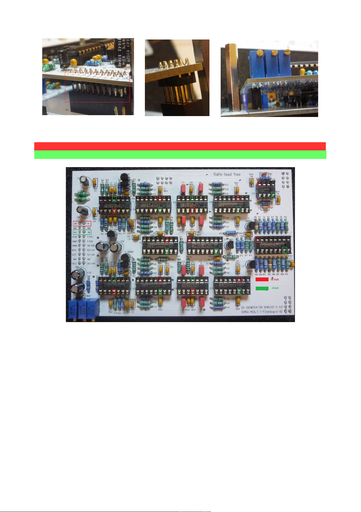
The adjustment of the filterboard.
Required tools - a frequency meter - or our free filter calibration tool.
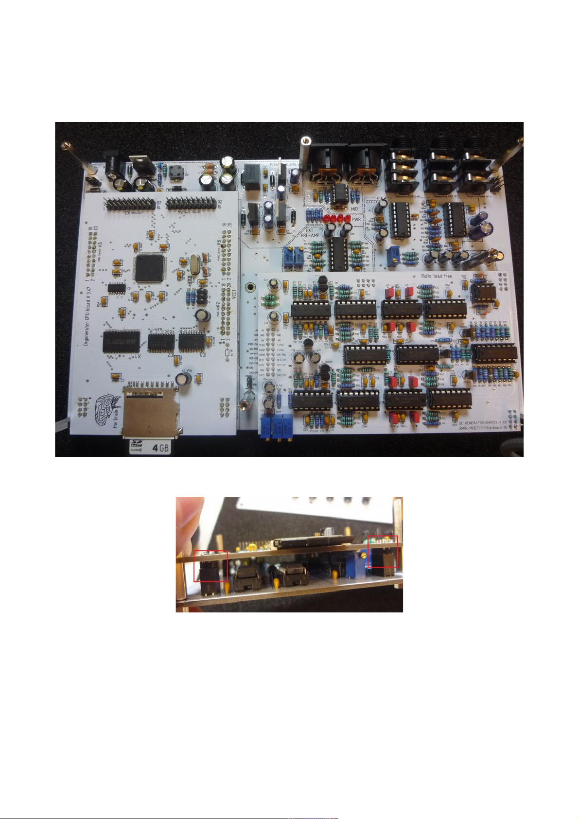
The SD-Ram card with the firmware must be inserted into the slot of the CPU board !
The filter installed in the de-generator is a -stereo filter !!.
This means that the right and left filter must be adjusted in V/OKT, and then again among
each other ! Sounds complicated, but it is not.
The de-generator is switched on. Both audio soc ets are connected to one -stereo input of
the amplifier.
There are three trim potentiometers on the filterboard.
R58=Lin 1 adjusts the linearity of filter 1 in V/OKT
10

R76=Lin 2 adjusts the linearity of filter 2 in V/OKT
R33= adjusts the filter balance
Please open ban 1 and load the sound program >>Filter-Adjust<< in the
De-Generator.
***The second encoder is used to set the ban . With the LOAD button , the sound program
is loaded at the lower left ***
Now the de-generator should play three tones in the LOOP.
Clic to listen to an audio sample>>> Filter alibration
These tones consist only of the filter resonance of both filters
Since both filters have not yet been calibrated, it sounds very slanted.
First we adjust one filter. To do this we simply disconnect a plug from an audio output.
With the frequency meter we now measure the pitch of the three tones.
It is important that the pitch of the three tones doubles each time.
If the lowest tone is approx. 100 Hz, the middle tone should be 200 Hz and the highest
tone 400 Hz!
11

** At 80 Hz the middle tone is 160 Hz and the high tone 320 Hz.
Audio 1 output = R76, Audio output 2 = R58
The linearity of a filter is set with R58.
If you have now set one filter so that the frequency doubles every time, the other filter is
used.
The audio plug is connected to the audio output again - the second plug is disconnected.
The procedure is the same, but the linearity is now set with R76.
Attention - it is not important which frequency the second filter has.
It is important that the frequency doubles over the three tones!
Both audio connectors are connected to the de-generator.
The first filter now has e.g. 80,160 and 320 Hz.
and the second filter now has e.g. 120,240 and 480 HZ
Now R33 , the balance control, is used. This is adjusted so that both filters now have the
same frequencies. This means, in our example the frequency of the first filter is increased
from 80 to 100 Hz, the frequency of the second filter changes from 120 to 100 Hz.
Now both filters oscillate with the lowest frequency to 100 Hz, then 200 Hz and 400 Hz.
Bboth filters are adjusted. The filters are optimally adjusted if both filters have only slight
beatings against each other.
*** Note. The procedure of the filter adjustment must be carried out several times in order
to reach a beat zero with almost both filters over three frequencies.
Slight beats are always there - they are analog filters.
The adjustment of the filters is now finished.
To adjust the motherboard.
While MIC-VOL, DELAY TIMING and VCA 1-2 offset can be adjusted from the front, EXT
VOL, SCOPE-VOL and DELAY VOL are adjusted from the top.
To do this, the panel board must be connected and tilted bac wards.
See the picture with the pen.
12

Attention, please note that there is no short circuit between the ribbon cable and the
switching regulator.
EXT-Volume R74 adjusts the volume of an external input signal.
The setting is uncritical. It should be set to avoid overdriving. That was already all to the
setting.
Scope Volume adjusts the amplitude of the built-in oscilloscope in the degenerator and
should be set with a sine or sawtooth so that no clipping of the signal occurs in the
oscilloscope window.
First we adjust the SCOPE-VOLUME with R73.
Load Bank 3 the sound > SCOPE-VOL-SAW
13

The SD RAM card must be inserted into the CPU board. After switching on
of the de-generator a TubeOhm logo should appear.
The de-generator is connected to MIDI and audio.
Then the selection window for the sounds is displayed.
Press button 1 to enter the Oscillator menu.
Then a sound is played on the MIDI eyboard.
On the left is the waveform played, on the right the oscilloscope window.
wrong
You see the sawtooth clipping up and down.
Now the trim potentiometer R73 is used to adjust the sawtooth so that it loo s as shown in
the picture below.
rright
The oscilloscope signal is pic ed up behind the filter. Therefore it is slightly bent .
Here again with a sinus .
Load Bank 3 the sound > SCOPE-VOL-SIN
Incorrect setting of R73
richtig
14

I now you have to loo over the panel board and twist the nec - but the adjustment
should be done once.
Now comes the DELAY volume
Delay Volume can only be adjusted correctly if the Delay Timing is set with
R100 is set correctly.
So the delay timing has to be set first !
Procedure for setting the DELAY timing:
The de-generator is connected via the audio soc ets in -stereo.
Load ban 3 the sound > ECHO-CALIB .
There is a crac ing sound from both loudspea ers.
Clic here for an audio sample: Delay alibration
The trimming potentiometer R100 (DELAY-Timing) is now set so that the crac ling can be
heard in both spea ers at the same time. While setting R100 you can hear that one
channel seems to crac ahead or behind. The correct setting is reached when the
crac ling comes from both spea ers at the same time.
Now the timing of the PT2399 is adjusted.
Our PT 2399 is a little sensitive. If the input signal is too large, it distorts - if it is too low, it
rushes. The delay (input) volume must be adjusted so that the PT 2399 does not distort
even when the filter resonance is fully turned up. For this purpose we have programmed a
sound which is especially suitable for delay volume adjustment with R48.
Download Ban 3: Sound:>> Delay Volume.
Use the R48 potentiometer to adjust the volume so that no distortion can be heard when
changing notes.
Clic here to listen to an audio sample: Echo-volumen- alibration
This completes the delay volume calibration.
Now the last settings have to be made on the motherboard.
15

the preamplification of the microphone preamplifier with the potentiometer R93 MIC
Volume
First the Sample-Record menu is opened.
opened.
Then the microphone preamplifier is adjusted with R93 in
such a way that when spea ing loudly the level indicator
goes to the 0 dB limit.
If the preamplifier is set too sensitive then the noise is too
strong, if it is too insensitive you have to spea too loudly.
Finished .
The setting of both VCAs
Download Ban 3: Sound:>> init
digital circuits and also the operational amplifiers have
-offset voltages. So you can hear the oscillators
shimmering through at the audio output, although the VCA
should be completely closed.
With the Trimmpotis R17 and R31 both VCAs are adjusted so that they close completely
and no sound can be heard anymore.
To do this, connect both audio outputs of the de-generator to an amplifier and turn it a little
louder. The de-generator should NOT be played with MIDI.
Then turn R31 until you hear a sound on one channel.
Now turn R31 in the opposite direction until the sound is no longer audible.
VCA1 is now set.
The same procedure is now done with R17 and set VCA 2.
16

Why all that?
You should thin that the CPU puts the PWM SIGNAL which control the VCA directly on
ground. In practice it can also be 0.1 Volt. Then come the -offset
voltages of the operational amplifiers and you might already have 0.2 volts.
These 0.2 volts generate a current that is sufficient to drive the amplifier.
Since the oscillators are always running, you can hear a sound even if the de-generator is
not played. With the two potentiometers for each VCA the operating point is shifted so that
Ground is actually Ground =0V . Thus the amplifier completely closes .
Congratulations - your de-generator is now ready to use.
17
Other manuals for De-Generator
2
Other TubeOhm Synthesizer manuals