manuals.online logo
Brands
  1. Home
  2. •
  3. Brands
  4. •
  5. TubeOhm
  6. •
  7. Synthesizer
  8. •
  9. TubeOhm Jeannie User manual

TubeOhm Jeannie User manual

Other manuals for Jeannie

1

Other TubeOhm Synthesizer manuals

TubeOhm Phoenix/Shruthi CD4069 Filter edition User manual

TubeOhm

TubeOhm Phoenix/Shruthi CD4069 Filter edition User manual

TubeOhm De-Generator User manual

TubeOhm

TubeOhm De-Generator User manual

TubeOhm De-Generator User manual

TubeOhm

TubeOhm De-Generator User manual

TubeOhm De-Generator User manual

TubeOhm

TubeOhm De-Generator User manual

TubeOhm Jeannie User manual

TubeOhm

TubeOhm Jeannie User manual

Popular Synthesizer manuals by other brands

NEON CAPTAIN Radioator user manual

NEON CAPTAIN

NEON CAPTAIN Radioator user manual

Roland JD-800 owner's manual

Roland

Roland JD-800 owner's manual

Joranalogue Contour 1 user manual

Joranalogue

Joranalogue Contour 1 user manual

Full Bucket Music Mono/Fury manual

Full Bucket Music

Full Bucket Music Mono/Fury manual

IK Multimedia UNO Synth PRO X user manual

IK Multimedia

IK Multimedia UNO Synth PRO X user manual

Kawai MP7 Software update

Kawai

Kawai MP7 Software update

Roland Gaia SH-01 Quick guidebook

Roland

Roland Gaia SH-01 Quick guidebook

Behringer DEEPMIND 12 quick start guide

Behringer

Behringer DEEPMIND 12 quick start guide

Yamaha S90 ES owner's manual

Yamaha

Yamaha S90 ES owner's manual

Roland GR-30 manual

Roland

Roland GR-30 manual

Moog Minitmoog 300A Owner's service manual

Moog

Moog Minitmoog 300A Owner's service manual

Gotharman Gotharman's anAmoNo-box user manual

Gotharman

Gotharman Gotharman's anAmoNo-box user manual

QuStream HDFS-550 Technical manual

QuStream

QuStream HDFS-550 Technical manual

Yamaha V50 Authorized product manual

Yamaha

Yamaha V50 Authorized product manual

Akai AX80 Operator's manual

Akai

Akai AX80 Operator's manual

Roland GS-500 instructions

Roland

Roland GS-500 instructions

Octave Cat SRM Service manual

Octave

Octave Cat SRM Service manual

Dreadbox Murmux Initiate manual

Dreadbox

Dreadbox Murmux Initiate manual

manuals.online logo
manuals.online logoBrands
  • About & Mission
  • Contact us
  • Privacy Policy
  • Terms and Conditions

Copyright 2025 Manuals.Online. All Rights Reserved.

TubeOhm Instruments
in cooperation with Rolf Degen
present:
Jeannie
polyphoner Synthesizer
the electronic part
DIY Manual V 1.0 / 05.08.22
TubeOhm 2021
1
Jeannie - DIY Synthesizer , technical data
•ower supply unit 12 V DC -minimum 1 A , plug 5.5 - 2.1 center positive
•micro SD RAM Karte 8..16 GB
•ower consumption 3.6 Watt
•8 Voices polyphonic
•multimode Filter
•2x ADSR
•2x LFO
•10 Waveshaper
•960 different waveforms per oscillator
•2 Oszillatoren pro voice
•xor, xmod, modulo, and, or and FM
•8-fold unison mode with up to 16 oscillators / one voice
•FX with Hall , Chorus, Delay , itchshifter, uvm.
•adjustable clock frequency for the FX DS - dirty effects
•2048 programmes can be stored on micro SD card
•graphic LCD display
•Teensy 4.1
•DIY friendly
Changes in V 1.01 : C 16,20 = now 100 nF, with this the encoder works better . Also C9 and C15 is now 1 uF
instead 4,7 uF.
Changes in V 1.05 . The AD converter board is now soldered directly to the board with the pins.
The coils L1,2,3,4 and on the FX board L23 can have 3.3 uH or also 4.7 uH.
Changes in V 1.06 : bugfix in the DIY manual
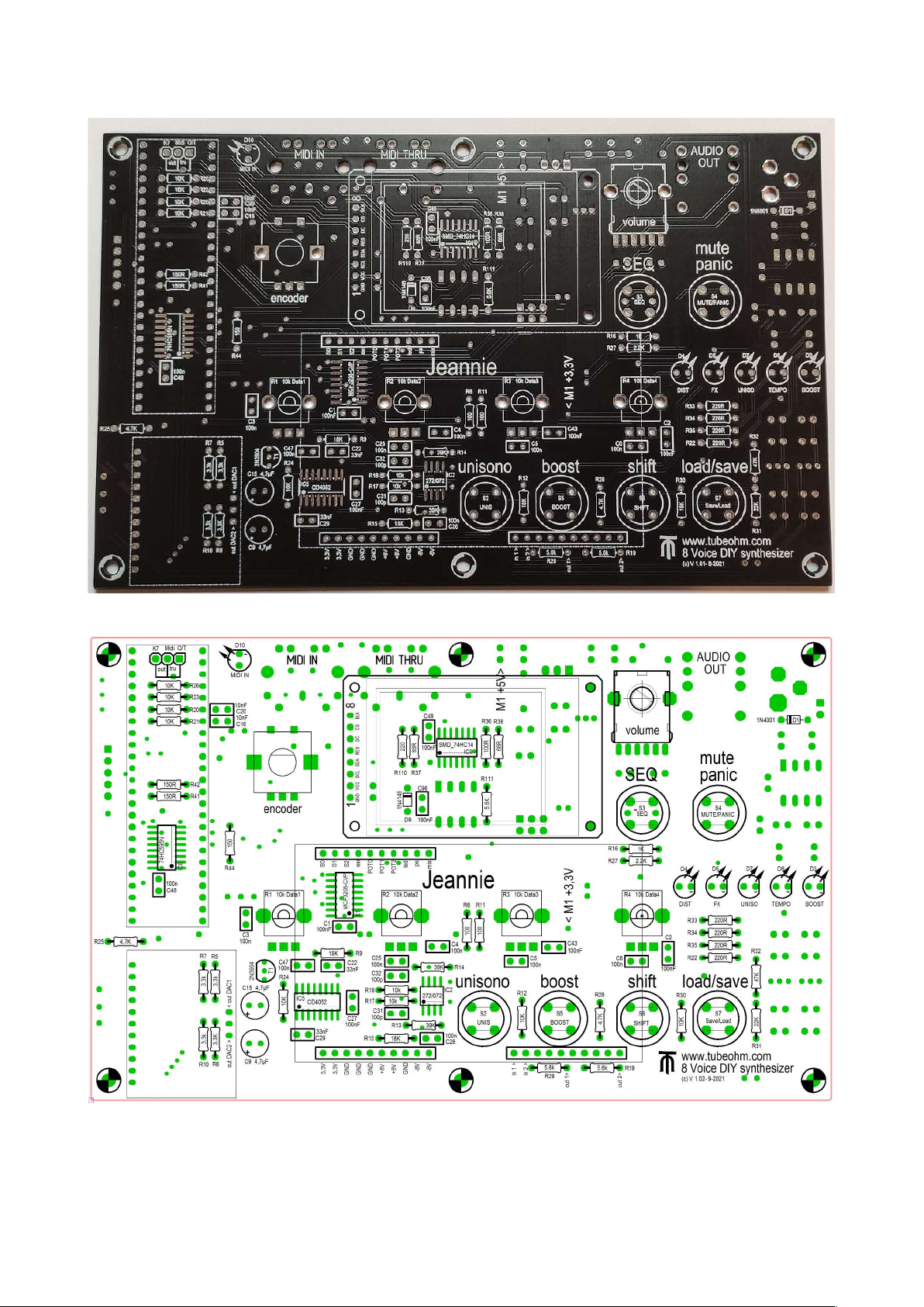
To build Jeannie we need some basic parts
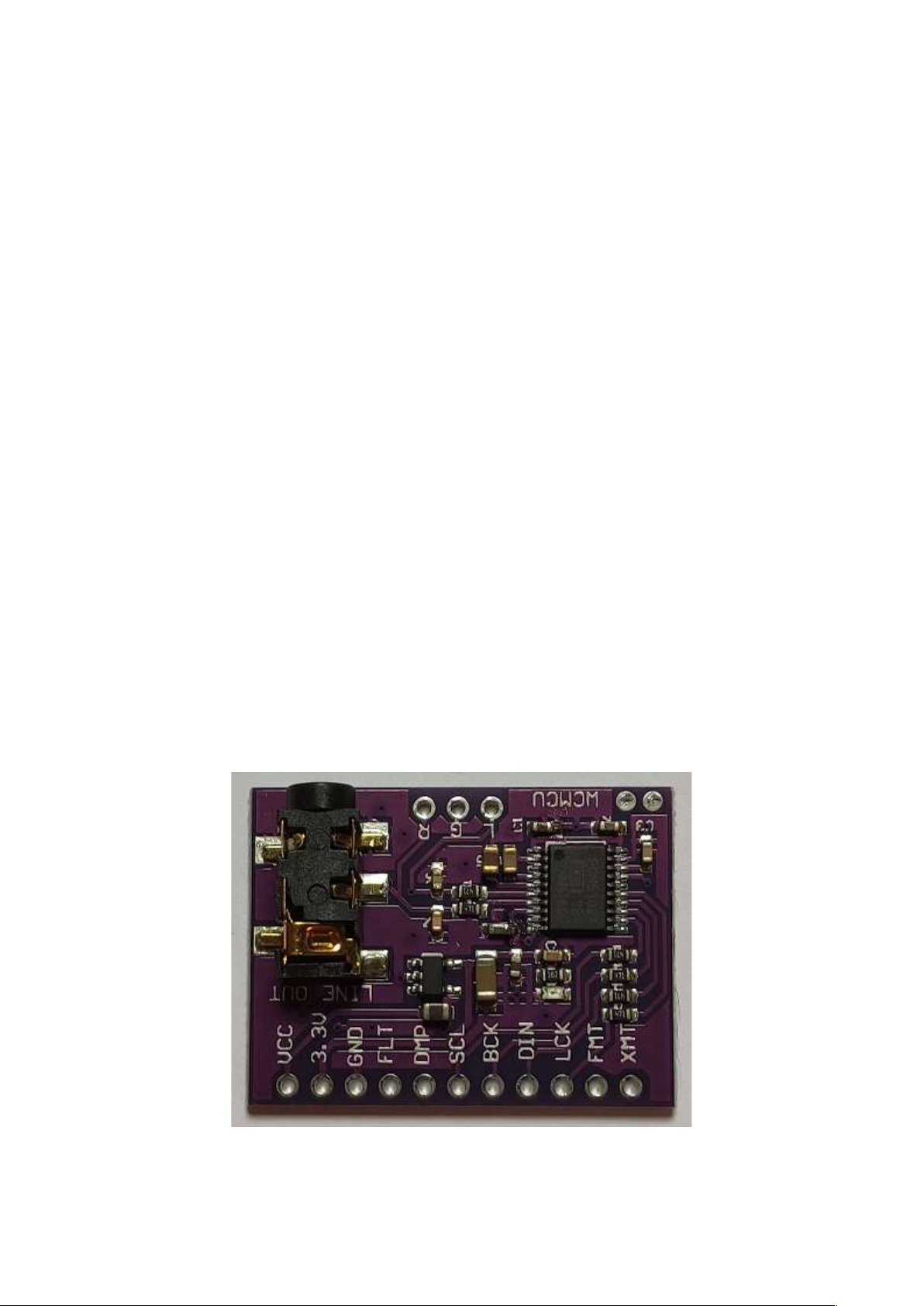
First of all, the PCM 5102A AD converter is ready build on a circuit board. This is included in the full kit and
tested. You can also find it at various suppliers such as Amazon/Alibaba/Banggood.
The important thing is 11 pins on one side and three on the other. I mention it specifically because there are
two designs. The pins are soldered on from below
AD Wandler 24 Bit with CM 5102A
2
The most important element is of course the Teensy 4.1, which is available from various distributors such as
Reichelt. A heat sink is glued to the Teensy and the USB 5 volt - described below - is changed. The two pin
headers are soldered in from below.
Teensy - 800 MHZ clock
Switching power supply - DC 12 V , 1 A, Plug 5,5 – 2,1 center positiv-
3
Introduction:
It's amazing what has happened in electronics in recent years. Synthesizers that used to be as big as a
cabinet have now shrunk to the size of a Eurocard and are even suitable for DIY.
I ask all interested DIY'ers to read this manual at least once BEFORE you build Jeannie.
Although it is relatively easy to build Jeannie, you should have some experience in soldering.
You should also be familiar with the component/part labels.
You have not only bought a DIY kit but also the experience of building your own synthesizer.
In this sense, have fun while building and even more fun while playing the instrument.
***Depending on the supplier, the components may look different or have a different colour. The important
thing is the value and the pitch !
TubeOhm 28.08.21
1:) first works (IM ORTANT)
First of all, we should switch the Teensy 4.1 to external power supply so that it is not
forgotten.
**** The Teensy is supplied with 5 V from the Jeannie. When programming a new firmware
via USB, the Teensy also gets 5 V from the PC. Since there can be voltage differences
between the PC and the Jeannie, a line on the Teensy MUST be disconnected.
Bild 1
You can see the underside of the Teensy
4.1 here.
Both PADS are connected by a very narrow
cable.
This wire is cut with a cutter
cutter knife or a razor blade or even a sharp
knife.
Now the 5V USB power supply is
interrupted. Only the USB data lines are still
active.
**The Teensys supplied by TubeOhm are
already switched to external and have the
latest firmware.
4
The Teensy 4.1 also needs a heat sink (picture 2) because we are running it within the
specifications but with a slightly higher clock speed.
Figure 2
So the preliminary work is done for now.
2:) the SMD components
For a long time we have resisted using SMD components in DIY projects.
Unfortunately, certain components are only available as SMDs. To make soldering easier,
we have lengthened the pads on the board considerably.
And, to be honest, with a little practice, the components can be soldered without any
problems. Even by hand.
If you have ordered a board with soldered SMD ICs from TubeOhm, you can skip the next
chapter 'Soldering the SMD components - procedure'. If not - please read on.
In the Jeannie we use SOIC (small outline ICs) 14,1 ,8. These are just solderable.
Pay attention to pin 1 on the IC. If the IC is soldered the wrong way round, the whole
circuit will not work and in the worst case the board will be broken.
5
Figure 3
Figure 3 shows how pin 1 on the IC is marked.
Either:
a:) by a dot or indentation
b:) one side of the housing is slightly bevelled.
The counting is from the left ,pin 1, to the right, pin 7 SO 14 or pin 8 SO 1 .
On the PCB, pin 1 of the ICs is marked, this with a dot and also with a symbolic bevel
Soldering the SMD components- rocedure
The connections pin 1 and pin 8 (SOIC 14) or pin 1 and pin 9 (SOIC 1 ) are tinned on the
board. Place the IC as straight as possible on the pads and hold it firmly with your fingers.
The soldering iron tip should be cleaned of solder residue. Use the soldering iron tip to
quickly press pin 1 of the IC into the tinned pad 1 of the PCB.
Repeat the same procedure with pin 8/9. The IC is now soldered to pins 1 and 8/9 on the
board.
Figure 4
When the IC is straight, the other legs of the IC are carefully soldered on. If you use a little
soldering honey as an additional flux, the solder flows from the pads directly to the legs.
Soldering the SMD ICs is actually the most difficult part of the job.
Now let's turn to the board and get started .
Here is the front side of the board again
Figure 5
Figure 6
7
And here is the back
Figure 7
Figure 8
8
Now it's time for soldering.
We start with IC 5 CD 4052. Attention: This IC MUST be a CMOS IC. Because this IC gets
a supply voltage of +/- 8 volts.
First we tin pin 8 on the board.
Figure 9
Then the IC is aligned and soldered to the leg.
Figure 10
9
Then the IC is straightened and pin 1 is soldered.
Figure 11
Now the IC can be soldered completely. The connections of the IC are cleaned with a
cotton swab and a cleaner and the solder pads are checked with a magnifying glass.
Figure 12
The remaining ICs are soldered using the same procedure.
*** First solder one pin, align it, solder the second pin and then solder it completely.
Attention, you should clean the tip of the soldering iron more often !
10