8
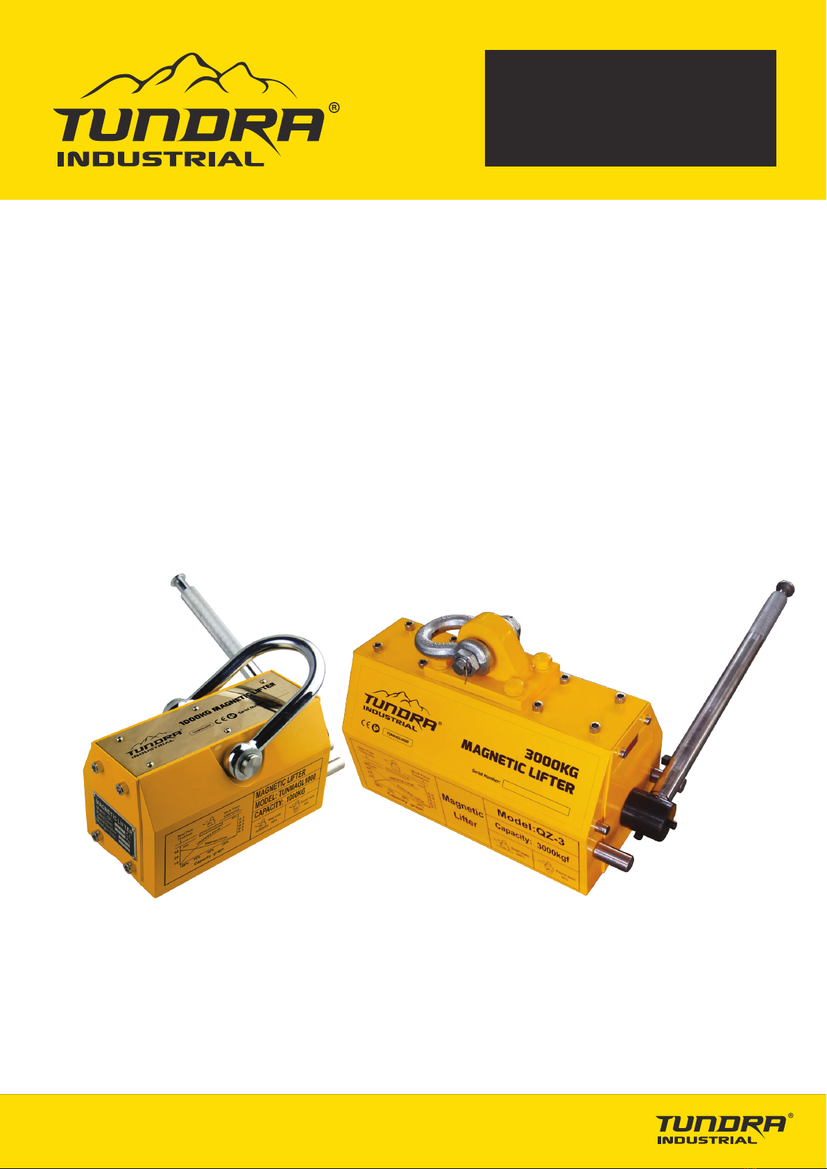
TUNMAGL0100 • TUNMAGL0300 • TUNMAGL0600
TUNMAGL1000 • TUNMAGL2000 • TUNMAGL3000 • TUNMAGL5000
v1.3
USER MANUAL
LIMITED WARRANTY STATEMENT
Tundra Industrial warrants its customers that its products will be free of defects in workmanship or material.
Tundra Industrial shall, upon suitable notification, correct any defects, by repair or replacement, of any parts or components of
this product that are determined by Tundra Industrial to be faulty or defective.
This warranty is void if the equipment has been subjected to improper installation, storage, alteration, abnormal operations,
improper care, unauthorised service or repair.
Warranty Period
Tundra Industrial will assume both the parts and labour expense of correcting defects during the stated warranty periods below.
All warranty periods start from the date of purchase from an authorised Tundra Industrial dealer. If proof of purchase is not
available from the end user, then the date of purchase will be deemed to be 3 months after the initial sale to the distributor.
1 Year
• TUNMAGL0100 • TUNMAGL0300 • TUNMAGL0600 • TUNMAGL1000 • TUNMAGL2000 • TUNMAGL3000 • TUNMAGL5000
90 Days
• All replacement parts purchased outside of the warranty period
Important: All parts used in the repair or replacement of warranty covered equipment will be subject to a minimum of 90 days
cover or the remaining duration of the warranty period from the original date of purchase.
Warranty Registration / Activation
You can register and activate your warranty by visiting the Jefferson Tools website using the following address:
www.jeffersontools.com/warranty and completing the online form. Online warranty registration is recommended as it eliminates
the need to provide proof of purchase should a warranty claim be necessary.
Warranty Repair
Should Tundra Industrial confirm the existence of any defect covered by this warranty the defect will be corrected by repair or
replacement at an authorized Tundra Industrial dealer or repair centre.
Packaging & Freight Costs
The customer is responsible for the packaging of the equipment and making it ready for collection. Tundra Industrial will arrange
collection and transportation of any equipment returned under warranty. Upon inspection of the equipment, if no defect can be
found or the equipment is not covered under the terms of the Tundra Industrial warranty, the customer will be liable for any
labour and return transportation costs incurred. These costs will be agreed with the customer before the equipment is returned.
Warranty Limitations
Tundra Industrial will not accept responsibility or liability for repairs made by unauthorised technicians or engineers. Tundra
Industrial's liability under this warranty will not exceed the cost of correcting the defect of the Tundra Industrial products. Tundra
Industrial will not be liable for incidental or consequential damages (such as loss of business or hire of substitute equipment etc..)
caused by the defect or the time involved to correct the defect. This written warranty is the only express warranty provided by
Tundra Industrial with respect to its products.
Any warranties of merchantability are limited to the duration of this limited warranty for the equipment involved. Tundra Industrial
is not responsible for cable wear due to flexing and abrasion. The end user is responsible for routine inspection of cables for pos-
sible wear and to correct any issues prior to cable failure.