9
4. Modes of Use
Walk Test Mode
In order to ensure that the Motion Sensor 869 has been mounted in the optimum
position to detect movement whilst minimising false activations, it is recommended
that a walk test is undertaken. This is achieved by placing the sensor in ‘walk test’
mode and then asking the end user to move in front of the lens, to ensure that they
are detected. The red LED will illuminate upon detection of movement.
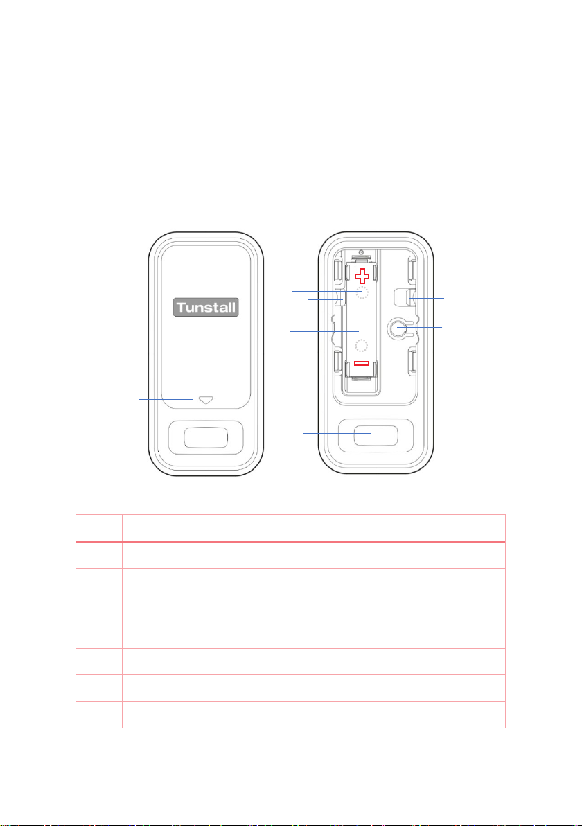
To activate ‘walk test’ mode:
1. Press and hold the ‘function’ button until a solid red LED is displayed.
2. Continue to press the ‘function’ button for approximately three seconds until the
red LED turns off.
3. Release the ‘function’ button. The Motion Sensor 869 is now in ‘walk test’ mode,
which will be active for three minutes. The timer will not be reset if the sensor
detects movement during this time.
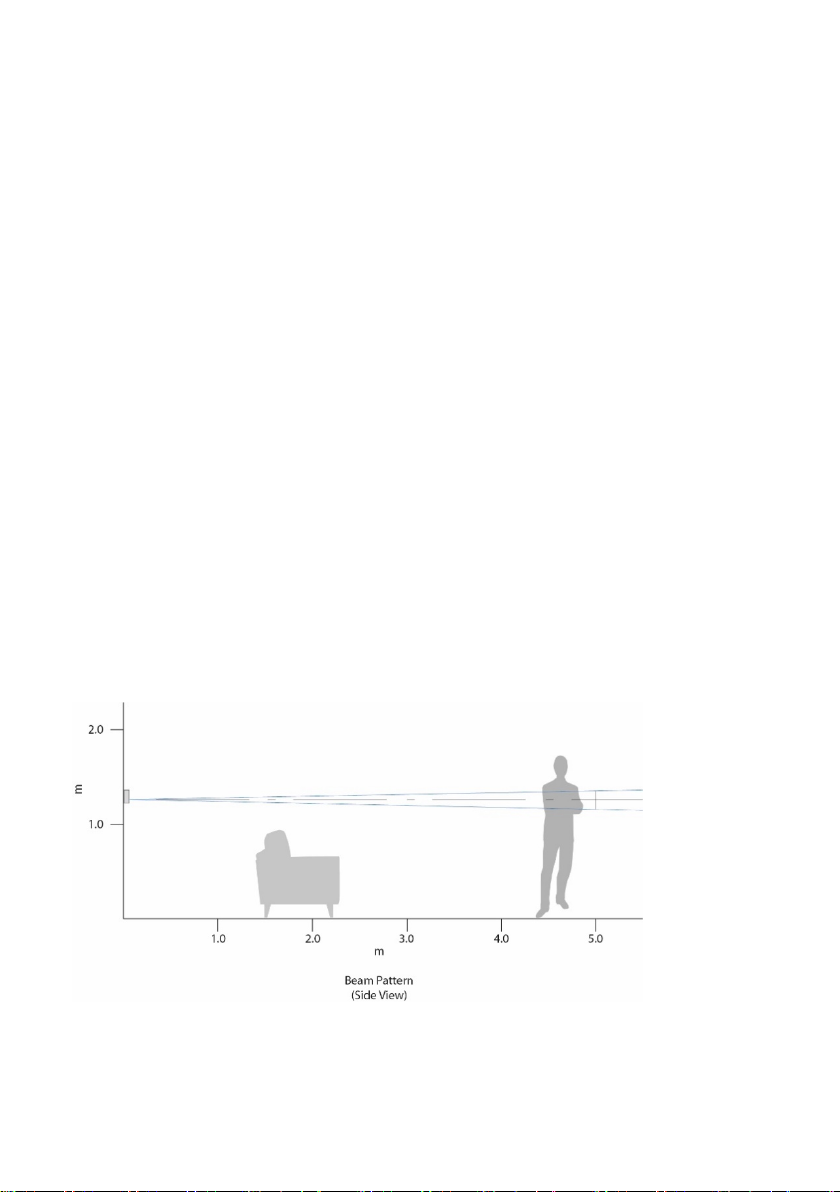
4. Ask the user to walk in front of the sensor. The detection beam should be
pointing at the chest area for optimal detection.
5. Once the user’s movement has been detected, they should move away from the
sensor for three minutes so that the sensor will revert to its normal operation
mode.
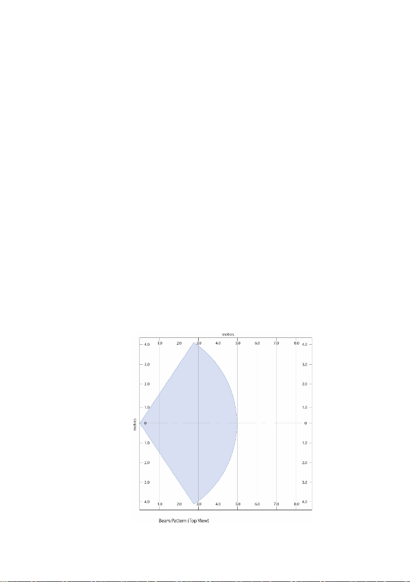
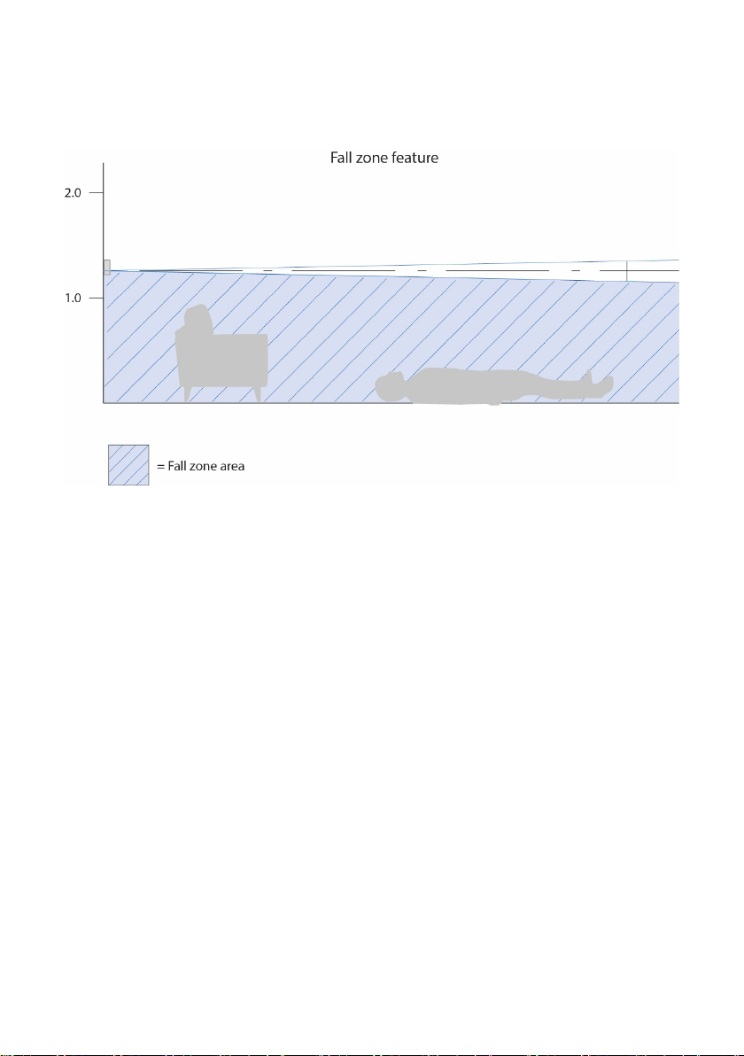
Fall Zone
The ‘fall zone’ feature is designed to ignore activity if the user has fallen on the floor
and is moving around, therefore disregarding any activity that might suggest that all
is well in the user’s home and ensuring that alarm calls are raised.
To achieve this, the sensor must be positioned at a minimum of 1.0m high from the
floor.
The ‘fall zone’ feature also reduces the likelihood of pets generating false alarms
when being used in wellbeing scenarios for activity monitoring.