Circuit Wiring and System
Expansion
Introduction
Reference will be made to Zones and Circuits when
explaining typical configurations. It is therefore
necessary to understand the difference between them
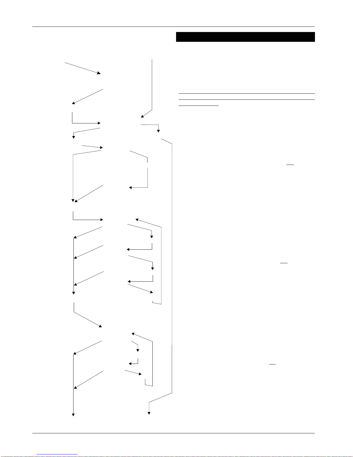
when used in this context. It will be helpful to refer to
Figure 1 (page 5) which shows the connection and use
of end-of-line and shunt resistors across normally closed
contacts.
Normally closed circuits
Each detection circuit may have up to ten normally
closed (N.C.) contacts, excluding tamper only type (0),
2 knock-night type (3) and shunt-lock circuit type (6).
Each contact must have a 4k7 shunt resistor fitted to
enable the CPA6 to continuously monitor the circuit
wiring.
An end-of-line (E.O.L.) resistor must always be fitted to
each circuit. Detection circuits may be wired in twin
cable, and make use of a remote resistor at the ‘End of
Line’.
Alternatively,iffourcorecableisused,theE.O.L.resistors
fitted at the termination block of the control panel may
be utilised for detection circuits wired directly to the
control panel.
Tamper Contacts
Tamper contacts are wired in series with the detection
circuit and no shunt resistor is fitted.
NOTE: The tamper link/contact of a detector device
must be wired in the opposite leg of the circuit to the
detector contact.
Detection Circuits
Detection circuit types, e.g. P.A. 24 hr. etc. connected
to each zone or Z.E.M loop are defined during
commissioning and can be any of the eight types listed
below:-
CIRCUIT TYPES
TYPE 0 - Tamper-only circuit
This definition is given to a detection circuit not
connected at the commissioning stage, (i.e.
circuits available for future expansion).
TYPE 1 - Night circuit
Where detection circuits are to be active only
when the system is in the test/set condition, this
definition is used.
TYPE 2 - 24-hour Circuit
This type is selected when continuously
monitored detectors are connected, (typically
fire doors, tube and wire framing etc). Circuit
operation will cause the fault audible tone,
when the system is open, and a main alarm
condition when the system is set.
TYPE 3 - Double-Knock night circuit
This option is programmed where two devices
have to be operated simultaneously when the
alarmsystemisset,beforeanalarmconditionis
generated.
NOTE: During setting, if either of the two devices
connected to this type of circuit is operated, then a
fault condition will occur, which will inhibit the system
from being set.
TYPE 4 - P.A. Circuit
This definition is given to Personal Attack buttons
and any other detectors which are required to
operatethe panel’s P.A.outputonly. Thistypeof
circuit is always active.
TYPE 5 - Exit/Entry Route Circuit (intermediate)
Detection circuits that may be operated during
exit and entry are defined thus. This type of
circuit is shunted during authorised entry to the
premises, but will cause a main alarm if
operated whilst the system is set.
TYPE 6 - Last exit contact/Shunt lock circuit
Either the final exit door contact, or shunt lock
fitted to the final exit door must be defined as
this circuit type.
TYPE 7 - Test circuit
Full details of the first operation of a detection
circuit defined thus, will be stored in the panels
event log, but will not cause any operation of
alarm fault outputs. A circuit on test and in fault
condition will not inhibit setting the alarm
system.
Thefollowingtypesofdetectioncircuitsmayadditionally
be programmed as User ‘shuntable’;-
a) Type 1 - Night circuit.
b) Type 2 - 24-hour circuit - may be made
shuntable only whilst the alarm
system is open.
c) Type 3 - 2 knock night circuit.
d) Type 5 - Exit/Entry (intermediate) circuit.
496524 Issue A 3of16 CPA6
CPA6