turbionaire trend+ User manual

trend
Multi-function axial exhaust unit
Unitate axială mulifuncțională de evacuare a aerului
Axiale Multifunktions-Absaugeinheit
Unidad de escape axial multifunción
Unité d'échappement axial multifonction
Scarico assiale multifunzione
Instruction manual EN RO GE SP FR IT
advanced fan


EN: CONTENT
PRECAUTIONS
INSTALLATION
ELECTRIC WIRING
REMOTE CONTROL DESCRIPTION AND ACTIVATION
DEVICE STATUS LIST
TROUBLESHOOTING
MAINTENANCE & SERVICE
PRODUCT DISPOSAL AND RECYCLING
1.
2.
3.
4.
5.
6.
7.
8.
4
7
11
12
15
16
16
17
NOTE: In case of an incorrect or unclear translation, only the English text applies.

1.PRECAUTIONS
Please read this manual carefully to operate this fan. Injury or even death can be
caused if these instructions are not applied!
Remove packing and make sure that the appliance is undamaged. In case of doubt do not operate the appliance and contact our service
center.
Immediately contact a qualified person (authorised dealer or the manufacturer) if the product is dropped or knocked to check its correct
functioning.
This appliance must only be used for the purpose it was built for, e.g. air exhaustion for domestic and similar purposes.
Do not leave parts of the packaging within reach of children or incompetent persons. To dispose of the packaging and the appliance at
the end of its useful life refer to the recycling norms in force in your country.
The device can be installed on the wall, window or ceiling. Air evacuation will be done, either directly outside, or in the existing central
ventilation duct of the building. The installation will be performed by a qualified electrician.
Do not leave parts of the packaging within reach of children or incompetent persons. To dispose of the packaging and the appliance at
the end of its useful life refer to the recycling norms in force in your country.
Immediately contact a qualified person (authorised dealer or the manufacturer) if the product is dropped or knocked to check its correct
functioning. The means of disconnection from the supply mains must have a contact separation in all poles and must provide full
disconnection under overvoltage category III conditions.
In the case of malfunction, anomaly or any type of fault disconnect the appliance from the electrical main supply and contact a qualified
person. Use only original spare parts for repairs.
·Damage can be caused to the device if the following instructions are not applied!
The product is to be installed at min 2.3 m above the floor and can be connected to the supply mains only if the voltage and the
frequency of the supply mains correspond to those written in the rating label.
The appliance must not be used to activate water heaters, room heaters, etc.
Do not use this product for uses that are different from those for which it has been designed.
After removing the product from its packaging ensure that it is complete and undamaged; if in doubt, immediately contact a qualified
electrician.
4

Do not touch the appliance with wet or humid parts of the body (e.g., hands or feet).
This appliance can be used by children aged from 8 years and above and persons with reduced physical, sensory or mental capabilities
or lack of experience and knowledge if they have been given supervision or instruction concerning use of the appliance in a safe way
and understand the hazards involved. Children shall not play with the appliance. Cleaning and user maintenance shall not be made by
children without supervision.
To avoid the risk of fire, do not use the product in the presence of inflammable substances or vapours such as alcohol, insecticides,
gasoline, etc.
Do not store the device out of the reach of children and disabled people if you decide to disconnect it from the power source and stop
using it.
If there is a fuel-powered device (water heater, gas boiler, etc. of the sealed chamber type) in the room where the product is to be
installed check that the re-circulation of air is sufficient to ensure a good combustion for the correct functioning of these devices,
therefore, precautions must be taken to avoid the back-flow of gases into the room from the open flue of gas or other fuel-burning
appliances.
ATTENTION: This symbol indicates that precautions that must be taken to avoid damage to the device.
Do not modify this device in any way.
Do not use the device when the ambient temperature is more than 40 °C.
Do not allow the product to be exposed to atmospheric agents (rain, sun, snow, etc.). Possible product applications are indicated in the
attached illustrations.
Do not sink the device or relative parts in water or liquids, except were indicated in the cleaning and maintenance section.
The air or fumes being extracted must be clean and free from greasy particles, soot, chemical and corrosive agents, inflammable or
explosive mixes. Its temperature must be below 50 °C (122 °F).
Do not obstruct the air inlet and outlet of the appliance in any way whatsoever. When using air ducting make sure that the ducting is not
blocked.
5

For optimum operation of the appliance, it is necessary to ensure an adequate re-circulation of air in the room. Consult the local norms
with regards to this.
In the case of malfunction, anomaly or any type of fault disconnect the appliance from the electrical main supply and contact a qualified
person. Use only original spare parts for repairs.
The device must be installed by a qualified electrician.
The electrical system to which the device is connected to must comply with the applicable standards.
The device is double insulated and therefore does not need to be earthed.
Do not operate the fan if a cable or plug is damaged, after a malfunction or if it has been dropped or damaged in any way.
The electrical power source / plug to which the device must be connected to must be able to provide the maximum electrical power
required by the device. Otherwise, contact an electrician to make the necessary changes before proceeding.
A multi-pole switch must be used to install the device. The distance between the switch contacts must be at least 3 mm.
Switch off the appliance using the main switch:
To ensure the unit adequate functioning, the room must have an adequate source to refresh the air. In addition, in case there is an
unsealed combustion-based appliance such as a water heater, gas stove, etc. in the same room, refreshing the air must be sufficient for
all devices to work efficiently together.
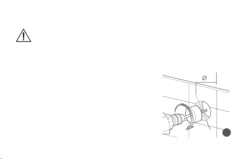
The device must discharge directly outdoors, through a short pipe (maximum length of 400 mm to ensure the standardized performance).
If the device is installed in pipelines subject to high levels of pressure, significant losses will occur. The device cannot be used to control
the water heaters, room heaters, etc. nor must it be connected to the hot air ducts used by other appliances.
Install the appliance so that the rotor cannot be accessible from the air outlet side. If this is not possible, a protection system must be
installed.
a) if the device does not work properly.
b) before cleaning the casing of the device.
c) if the device is not to be used for a long period of time.
6

103 mm
2. INSTALLATION
Attention: Make sure that the device is turned off using the main switch. Install the device near a
wall plug. The device must be installed by a qualified electrician.
A. WALL INSTALLATION
Make sure that you have chosen the correct supply voltage, according to the label, before
connecting the device to the power source.
Drill an appropriate hole in the wall and make sure that there are no cables or pipes inside
the wall when you perform this operation. The hole in the wall must have a slight
inclination towards the outside to allow the condensation to drain.
1.
2.
1
7

6 mm
W
2 3 4 5
3. Remove the front cover of the fan, place the fan on the wall and mark the four fixing points and where the cable enters the fan case, then
drill the screw holes into the wall..
Wall Wall
Wall
4. Bring the cable from a 2-pole switch to the unit. The distance between the poles should be at least 3 mm.
5. Pull the power cable to the fan, then fix the device in a stable position.
6 7 8 9
Wall Wall
8

103 mm
6. Then fix the front panel and the outside grid (the outside grid is not supplied, but it can be
purchased separately as an optional accessory).
B. WINDOW INSTALLATION
Before performing any cut, check if the window frames do not
obstruct the fan and keep in mind that there is necessary to
have enough space for fixing the fan casing.
Position the fan on the windowpane, mark it, then make the
appropriate cutout.
1.
2.
Wall
Glass
10
1
3.Bring the cable from a 2-pole switch to the unit. The distance between the pins should be at least 3 mm.
4.Use glass glue (not included) to fix the fan body, following the instructions for use.
5. Apply glue on the entire edge, then fix the fan body to the glass.
am
s
2 3 4 5
Glass
Glass Glass

Choose the installation place and drill a hole in the ceiling with a diameter corresponding to the size of the fan outlet.1.
103 mm -
C. CEILING INSTALLATION
1 2 3 4
2. Remove the front panel of the fan, bring the power cable from a 2-pole switch to the
unit. The minimum distance between the 2 poles is of 3 mm.
5
3. Pass the power cord through the hole provided and fix the unit in a stable position using the fixing devices (these are not provided).
67 8
10

9
4. The units mounted in the ceiling must discharge the air outdoors, not in the space between the
false ceiling and the ceiling itself, using a flexible pipe and the corresponding anti-return valve.
NOTE: If the unit is mounted on the piping (not included), it is necessary to install this piping in
such a way as to avoid the entry of gases from gas-burning appliances or other fuel-burning
appliances into the room.
3. ELECTRICAL WIRING
The fan is double insulated (class II) and
does not need to be earthed.
L – phase
N – neutral
The connectors are located on the fan base
to ensure the degree of protection (IP)
against water splashes. The fan is
permanently supplied with voltage by
means of a 2 conductor-cable of min 1 mm
section each.
Electrical
connection
diagram
without light
PCB
M
NL
L
NPower Supply
Switch
Fan internal
connection
Terminal
block
L N
M
NL
L
NPower Supply
Switch
L N
Light
Electrical
connection
diagram
with light
PCB
Terminal
block
Fan internal
connection
11

A. REMOTE CONTROL PAIRING TO THE VENTILATION UNIT
Press the "RESET" button on the device to be connected to the remote control, for at least 5 seconds. When the LED flashes BLUE,
synchronisation mode has begun. To confirm the pairing, press any button on the remote control (except the “ON/OFF” key). The pairing is
complete.
4. REMOTE CONTROL DESCRIPTION AND ACTIVATION
The remote control is a radio transmitter designed to control the unit. Remove the
transparent pull tab from the remote-control battery compartment. Since then, the
remote control is activated and operates within a range of approximately 20 m (battery
in a good functioning state).
B. UNPAIRING REMOTE CONTROL FROM THE VENTILATION UNIT
Press the "RESET" button on the device to be disconnected from the remote control, for at least 5 seconds. When the LED flashes BLUE,
synchronisation mode has begun. To unpair, press any button on the remote control (except the “ON/OFF” key). The cancellation of the
pairing is complete.
C. PAIRING A REMOTE CONTROL WITH SEVERAL VENTILATION UNITS
It is possible to control several ventilation units (without the upper limit for the associated devices in the range of the remote control). In this
case, all the remote control functions will work on all the ventilation units.
12

D. DESCRIPTION OF REMOTE CONTROL
D.1. STANDARD FUNCTIONS
ON/ OFF
Unit ON/OFF1.
2. Static RED LED = OFF / BLUE LED = ON
CONTINUOUS VENTILATION MODE
1. The speed is automatically recuced to the minimum, up to gear 1
2. Any pressing of any button except ON/OFF, LED Light, Variator (Dimmer) button, cancels the continuous ventilation mode.
3. Continuous ventilation mode indicator LED: Static Green
1. Press the button to reduce from speed 6 to speed 2.
2.Press the button to increase from speed 2 to speed 6.
3.LED indicator: BLUE flashing with each press; speeds 1 and 6 are highlighted by the PURPLE flashing color.
FAN SPEED adjustment
TIMER
1. Briefly pressing TIMER button makes the fan work for 5 minutes at the speed, the it will stop.
2. Any pressing of any button ecept the ON/ OFF button, Ambient LED Lighting (for models equipped with this function) and DIMMER,
cancel TIMER mode.
3. LED indicator: Static Yellow
13

BOOST MODE
Briefly press BOOST key to increase fan speed to 7 for 5 minutes (standard configuration) after which BOOST mode is deactivated.
Any pressing of any button except the ON/OFF buttons, Ambient LED lighting (for models equipped with this function) and DIMMER,
cancels BOOST mode.
1.
2.
3. LED indicator: YELLOW flashing
AMBIENT LIGHT ON/OFF
Briefly press the “Ambient light” button, then the LED is on/off (only for models equipped with this function).
DIMMER
When it is pressed successively, the intensity of the LED indicator positioned on the side of the device will increase: after reaching the
maximum, the intensity restarts from the minimum (off) and increases again: after a short period of time in which DIMMER button was not
pressed, the intensity is considered set.
RESTORE TO FACTORY SETTINGS
Press the “RESET” button on the device for at least 5 seconds, when the LED flashes BLUE, release the button, then press it again the “RESET”
button until the LED indicator turns RED, and the setting from the factory is restored.
D.2. SPECIFIC FUNCTIONS
SETTING TIME FOR TIMER MODE
1. Press the Timer key and hold for at least 5 seconds, when the LED indicator flashes GREEN, press the keys
to adjust the timer (setting intervals: 1, 3, 5, 10, 20, 30 minutes);
2. LED indicator: Flashing PURPLE with each press, minutes 1 and 30 are highlighted by flashing BLUE).
14

Press the BOOST key and hold for at least 5 seconds, when the LED indicator flashes GREEN, press the buttons
to adjust the BOOST mode (setting intervals: 1, 3, 5, 10, 20, 30 minutes);
LED indicator: Flashing PURPLE with each press. When the BOOST Mode is set either to 1 minute (by pressing the Low Speed key ) or
to 30 min (by pressing the Hi Speed key ), the LED indicator will be flashing YELLOW
1.
2.
3.
SETTING TIME FOR BOOST MODE
5. DEVICE STATUS LIST
LED DESCRIPTION STATUS
Static RED Unit OFF
Static BLUE Unit ON
Static GREEN Continuous Ventilation
Flashing YELLOW BOOST MODE
Short Flashing PURPLE Min/Max SPEED
Short Flashing BLUE Speed Setting
Flashing YELLOW TIMER Mode
PERFORMANCE CHART
Static Pressure (Pa)
Air flow ( m³/h)
15

6. TROUBLESHOOTING
PROBLEMS CAUSES AND SOLUTIONS
The unit does not switch on. There is no power supply.
Check the main switch and/or electrical connections.
The impeller does not work. Check the device.
This device is equipped with a manual reset protection system that in the event of a mechanical
obstruction in the rotation will switch off the engine.
To restore normal operation, proceed as follows:
disconnect the device from the mains;
remove the cause of the mechanical obstruction (only qualified personnel);
reconnect the device to the mains.
The device will only resume normal operation if the protection system does not detect any additional
faults. If the fault persists, contact the client support service.
The devices do not
synchronise.
Disconnect and reconnect power supply.
The remote control
does not work.
Check the status of the battery.
7. MAINTENANCE & SERVICE
Before carrying out any maintenance, ensure the device is disconnected from the mains power supply.
1. Wipe down the device using wet soapy cloth only. Do not allow water to come into contact with any electrical part, such as the motor.
2. Never use petrol, benzene, thinner or any other such chemicals for cleaning the ventilating fan.
16

OONN
OFF
3. Do not immerse resin parts into hot water over 60°C.
4. Do not place hot objects near or install nearby hot
appliances.
The product was designed and assembled using high quality materials and components, which can be recycled and reused. If the symbol of a
barred container with wheels is found on a product, this means that the product meets the requirements of the Directive 2012/19/EU.
Find out about the methods of collecting electrical and electronic products in force in the area where the product is to be disposed of.
Comply with local waste disposal regulations and do not dispose of old products with normal household waste. A correct disposal of the
products helps to prevent environmental pollution and to prevent possible damage to health. Abusive removal of the product by the user
involves the application of administrative sanctions provided by the law in force. For more detailed information on available collection
systems, contact your local waste disposal service or the store where the product was purchased. Manufacturers and importers fulfill their
obligations regarding recycling, treatment and disposal in an environmentally compatible manner either directly or through participation in a
collective system.
8. PRODUCT DISPOSAL AND RECYCLING
DECLARATION OF CONFORMITY
Manufacturer and importer:
SC Intax Trading SRL - 14B Ion Creanga Str., 075100,
Otopeni, Ilfov, Romania
Tel (+40) 318 246 246 Fax (+40) 214 203 151
[email protected] www.intaxtrading.com
This product complies with the following European directives:
LVD 2014/35/EU
EMC 2014/30/EU
17

RO: CUPRINS
MASURI DE PRECAUTIE
INSTRUCTIUNI DE INSTALARE
CONEXIUNEA ELECTRICA
ACTIVAREA SI DESCRIEREA TELECOMENZII
LEGENDA STATUS DISPOZITIV
DEPANARE
INTRETINERE SI SERVICE
ELIMINAREA SI RECICLAREA PRODUSULUI
1.
2.
3.
4.
5.
6.
7.
8.
19
22
26
27
30
31
31
32
NOTA: In cazul unei traduceri incorecte sau neclare se aplică doar textul în limba engleză.

MASURI DE PRECAUTIE1.
ATENȚIE! Cititi cu atenție acest manual pentru a putea opera acest ventilator.
Nerespectarea acestor instrucțiuni poate provoca rănirea sau chiar moartea!
Scoateți ambalajul și asigurați-va că aparatul nu este deteriorat. In cazul in care aveți indoieli, nu folosiți aparatul și contactați centrul
nostru de service.
Contactați imediat o persoană calificată (distribuitor autorizat sau producător) dacă produsul este aruncat sau lovit pentru a verifica
funcționarea corectă a acestuia.
Acest aparat trebuie utilizat numai in scopul pentru care a fast construit, de ex. pentru evacuarea aerului și in alte scopuri casnice și
similare.
Nu lăsați părțile ambalajului la îndemâna copiilor sau a persoanelor fără discernământ. Pentrua elimina ambalajul și aparatul la sfârșitul
duratei sale de viață,consultați normele de reciclare în vigoare în țara dvs.
Dispozitivul poate fi instalat pe perete, fereastra sau plafon. Evacuarea aerului se va face, fie direct in exterior, fie in conducta existenta
de ventilatie centrala a cladirii. Instalarea se va face de catre un electrician profesionist calificat.
Nu lăsați părțile ambalajului la îndemâna copiilor sau a persoanelor fără discernământ. Pentru a elimina ambalajul și aparatul la sfârșitul
duratei sale de viață, consultați normele de reciclare în vigoare în țara dvs.
Contactați imediat o persoană calificată (distribuitor autorizat sau producător) dacă produsul este aruncat sau lovit pentru a verifica
funcționarea corectă a acestuia.
Deconectarea de la sursa de alimentare cu energie electrică trebuie să se facă prin intermediul unui întrerupător de deconectare de la
toţi polii, care să asigure deconectare integrală în cazul supratensiunii de categorie III.
In caz de defecțiune sau de funcționare defectuoasa, opriți aparatul, nu il atingeți, deconectati-l de la sursa de alimentare cu energie
electrica si contactati unitatea de service autorizata sau o persoana calificata. Daca sunt necesare reparații, contactați numai centrul de
service tehnic autorizat de producator și solicitați piesede schimb originale. Nerespectarea celor de mai sus ar putea pune in
pericolsiguranța aparatului.
Unitatea trebuie instalata la o inaltime de minim 2.3 m si poate fi conectată la rețeaua de alimentare electrica, numai dacă tensiunea și
frecvența rețelelor de alimentare corespund celor scrise pe plăcuța cu datele tehnice ale unității.
Unitatea nu trebuie folosită pentru a activa incalzitoare de apa, calorifere etc.
19

Nu folosiți acest dispozitiv în alte scopuri decât cele pentru care fost proiectat si care sunt descrise in manualul de instructiuni.
După scoaterea dispozitivului din ambalaj, asigurați-vă că acesta este complet și nedeteriorat; în caz de îndoială, nu instalati si nu
conectati dispozitivul la reteaua electrica si contactați imediat unitatea de service autorizata.
Nu atingeți aparatul cu părți umede ale corpului (de exemplu, mâini sau picioare). Nu atingeti aparatul cand sunteti cu picioarele goale.
Aparatul poate fi utilizat de către copii începând cu vârsta de 8 ani precum și de persoane cu capacități fizice sau psihice reduse sau fără
experiență cu condiția ca acestea să fie supravegheate și instruite de alte persoane responsabile cu privire la utilizarea echipamentului
intr-un mod sigur, precum si la riscurile implicate. Este interzis copiilor să se joace cu aparatul. Curățarea aparatului cât și întrețirea
acestuia nu se vor face de către copii.
Pentru a evita riscul de incendiu, nu utilizați unitatea produsul în prezența substanțelor și vaporilor inflamabili, precum alcool,
insecticide, benzină etc.
Nu depozitați aparatul la indemana copiilor și a persoanelor cu dizabilitați dacă decideți sa-l deconectați de la sursa de alimentare și sa
nu il mai folosiți.
Dacă există un dispozitiv alimentat cu combustibil (boiler, centrală pe gaz, etc. de tipul camera sigilata) în camera în care trebuie instalată
unitatea, verificați dacă aerul recirculat este suficient pentru a asigura o combustie bună pentru funcționarea corectă a acestor
dispozitive,astfel încât să luați măsuri de precauție pentru a evita reintrarea in incapere a gazelor provenite de la cosurile de evacuare
sau de la alte aparatele care ard combustibil. Luați toate masurile de precauție necesare pentru a va asigura ca nu exista infiltrari de gaz
in spațiile in care se afla aparatele cu combustie.
ATENTIE: Acest simbol indica masurile de precautie care trebuie luate pentru a evita deteriorarea
aparatului.
Nu efectuați modificari de niciun fel la acest aparat.
Nu folosiți aparatul la temperaturi ambientale mai mari de 40° C.
Nu expuneți unitatea la agenți atmosferici (ploaie, soare, zăpadă etc.). Condițiile de utilizare ale acestei unități sunt prezentate în manual.
lnspectați regulat aparatul pentru a vedea daca prezinta defecțiuni vizibile. Daca gasiți defecțiuni, nu utilizați aparatul.
Nu scufundați unitatea sau oricare dintre părțile sale în apă sau în alte lichide, cu excepția cazului în care este necesar în mod special în
timpul operațiunilor de întreținere.
20
Table of contents
Languages:
Other turbionaire Fan manuals
Popular Fan manuals by other brands

BV
BV BV-BF-01 instructions

Awenta
Awenta Vega WGB100H instruction manual

ansio
ansio 1100 instruction manual

Meaco
Meaco MeacoFan 260C instruction manual

Home Decorators Collection
Home Decorators Collection KENSGROVE YG493OD-ORB Use and care guide

Blue Blower Professional
Blue Blower Professional HV-20S owner's manual

Hydrofarm
Hydrofarm JETFAN JF13010 instruction manual

Broan
Broan QTR100FLT instruction manual

COOLTRON
COOLTRON PILLAR instruction manual

Kooltronic
Kooltronic Guardian Series installation instructions

Exido
Exido 271-017 Specification sheet

Addvent
Addvent Whisper Silent AVX100WT Installation and Maintenance