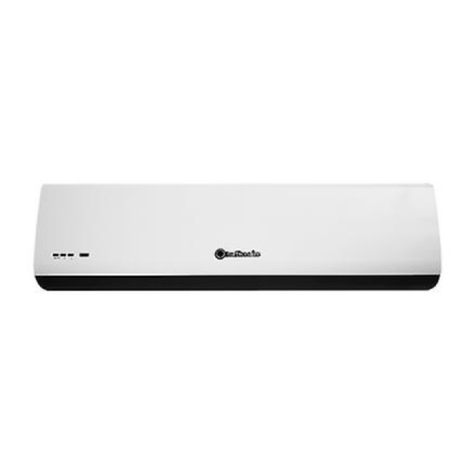
turbionaire AMBIO 90 User manual

Instruction manual EN RO DE ES FR IT
AIR CURTAIN
PERDEA DE AER
LUFTVORHANG
CORTINA DE AIRE
RIDEAU D'AIR
CORTINA D'ARIA
AMBIO 90/120/150/180
AMBIO HEAT 90T/120T/150T


DECLARATION OF CONFORMITY
(€ Manufacturer
:
Inta
x
Trading SR
L
, Str.
L
ibert
ăț
ii A1-A3,
140017,Ale
x
andria, Teleorman, Romania.
These products is conform to the following European Directives:
(Ambio 90/120/150/180)
LVD directive 2006/95/EC
EMC Directive 2014/30/EU
These products is conform to the following European Directives:
(Ambio HEAT 90T/120T/150T/180)
LVD directive 2014/35/EU
EMC Directive 2014/30/EU
Standards (Ambio 90/120/150/180)
EN 60335-1:2012+A11:2014, EN 60335-2-80:2003+A1:2004+A2:2009
EN6233:2008
EN 55014-1:2006+A1:2009+A2:2011, EN 5501-2:2015
EN 61000-3-2:2014, EN 61000-3-3:2013
Standards (Ambio HEAT 90T/120T/150T/180)
EN 60335-1:2012+A11:2014, EN 60335-2-80:2003+A1:2004+A2:2009
EN 6233:2008
EN 60335-2-30:2009+A11:2012
EN 55014-1:2017, EN 55014-2:2015, EN 61000-3-12:2011, EN 61000-3-11:2000
EN

1. PRODUCT INTRODUCTION
Air curtain (air door) is one of the new top-class products for modern decoration, it's the
equipment matched with the air conditioner. And it is installed above the entrances of
supermarket, theater, meeting room, hotel, office room, working shop and storeroom to
prevent the dust, mosquito and nocuous air, and so on.
Air curtain can effectively isolate convection indoor and outdoor and keep temperature.
Especially used in the location with air-conditioner to keep indoor environment and save
energy of refrigeration equipment. In addition, Air Curtain can prevent the invasion of
dust, pest and harmful fumes from outside. Maintain a comfortable environment inside.
2. IDENTIFICATION & INSTALLATION DIMENSIONS
Back side

3.3 Don’t install the unit too low, no
less than 2.3 meters from the ground. 3.4 When the entrance is wider than
the unit, it is recommended to install
two or more units in parallel. In this
case, provide 20-40mm gaps between
the units.
3.2 Please install the unit inside
the room.
3.1 Please install the unit in a sturdy
place to avoid the shaking and
ensure its security (because it
maybe causes the wall becoming
flexible or shaking and noising.)
3.5 Don’t allow gaps between the unit
and the wall. When hanging it from
the ceiling, purchase the extra ceiling
brackets.
3.6 Don’t install the unit in a place
where it is splashed by water, exposed
to excessive steam, explosive gas or
corrosive gas.
3. INSTALLATION CAUTION
Before installation, please apply the same voltage and frequency, then follow the below
requests when install the air curtain:

4. INSTALLATION
A. Installing on the concrete wall:
4.1.2 Fix the bolts in the proper position
(fix the position with the mounting plate
and pour cement into the bolt holes.)
4.1.1 Removed the mounting plate
Remove the plastic parts, unclamping
the fixed screws on the back of main
body toremove the mounting plate.
4.1.3 When the cement has freeze,
fit the mounting plate (use the
washer and nut according to the
following)
4.1.4 Install the main body
Set the main body onto the upper end of the
mounting plate, and clamp it as below. Make
sure it’s well fixing

B. Installing on the wooden wall
4.2.1 Fix the mounting plate in the
proper positions with tapping screw.
4.2.2 Same as the step 4.14.
C. Hanging from the ceiling
4.3.1 Remove the mounting plate from the main body (as in Figure 4.1.1)
4.3.2 Fixing ceiling brackets as Fig.
4.3.3 Set the mounting plate on the ceiling brackets and ensure safety & fixing
(use the bolts attached to the ceiling brackets as Fig. Using the ceiling brackets to hang
from the ceiling, the position of mounting plate can be adjusted in the limit of 100mm.

D. For above ceiling
4.3.4 Do the same as step A to install the
main body.
4.4.1 Fix the air curtain as in the procedure
for installing on the concrete wall. 4.4.2 Then install the pipe as below.
5. TECHNICAL PARAMETER
1
2
MOUNTING PLATE
2
1
PLASTIC PARTS

7. OPERATION
7.1. COOLING MODEL:
7.1.1. Turn on the power switch on the unit.
Select the air speed:High[H], Low[L]
7.1.2. Turn on by remote controller.
One button to control the working cycle at: Turn on at high speed – Low speed – turn off
6.ELECTRIC WORK
WHITE
BLUE(BROWN/RED)
YELLOW
c
MOTOR
ORANGE
(YELLOW)
BLACK
YELLOW-GREEN
RECEIVER
IC
HEATER
HEATER
N A B C PN
THERMAL CUT-OUT
THERMAL CUT-OUT
THERMAL CUT-OUT
com 1on
com 2on
com 3on
I/O
RECEIVER
BROWN
BLUE WHITE
GREY
YELLOW-GREEN
Cooling Model
Heating Model
7.2. HEATING MODEL:
7.2.1. Controlled by remote controller
a. Press “ON/OFF” button to turn ON the unit. Main receiver receives the signal with
the sound of “beep” to start working with the green light in cool mode at high speed “H”.
Press “ON/OFF” button again to turn OFF.

b. When the unit is working at the above a. situation, press “COOL” button in the
Remote controller, receiver receives the signal with the sound of “beep” and switch high
speed to low speed “L”. Meanwhile there is a green light display in the receiver. Press
“COOL” button again, the unit will switch low speed to high speed. So when the unit is
working at cool mode, press “COOL” button can switch air curtain working under the
cycle of Low or High speed.
c. When the unit is working at the above b. situation, press “HEAT” in the remote
controller, receiver receives the signal with the sound of “beep” and switch cool mode to
heating mode at low power. Meanwhile there is a Red light display in the receiver. Press
“HEAT” button again, the unit will switch low power to middle power. Meanwhile there is
TWO Red lights display in the receiver. Press “HEAT” button again, the unit will switch
middle power to high power. Meanwhile there is THREE Red lights display in the receiver.
Press “HEAT” button again, the unit will switch heating mode to cool mode and the red
lights display change to green light in the receiver. So HEAT function, when the unit is
working at cool mode, press “HEAT” button can switch air curtain working under the
cycle of heating low power, heating middle power, heating high power and then cool
mode.
d. When the unit works at cool mode, press “ON/OFF” button to turn OFF the unit.
e. When the unit works at heating mode, press “ON/OFF” button, the unit will
switch to cool mode at high speed, the indication light turns to green flicker light. The
unit will continue to work in cool mode for 30 seconds and then stop.(This is to ensure
the heater is been cooled down and has 30 seconds delay stop).
7.2.2. Controlled by the control panel in the unit is the same function as 7.2.1.
7.2.3. Overheat protection:
When the air curtain works at heating mode, there is overheat protection. When the
heater temperature is overheating, heating mode will stop and switch to cool mode
automatic, at the same time the indication light change to green light. When the
temperature drop down to a certain temperature, if want the unit to work at heating
mode, press “HEAT” button to continue to work heating mode.
7.3 According to the installation place to adjust the wind direction vanes to obtain
the best effect.
8. CAUTIONS
1) Turn off the power and disconnect the plug for any maintenance service.
2) Turn off the power or disconnect the plug in case of not use the product for long
time.
3) Make sure that the product connected with ground wire.
4) The pictures shown on this manual are illustrative only.
5) This appliance is not intended for use by persons (including children) with
reduced physical, sensory or mental capabilities, or lack of experience and knowledge,
unless they have been given supervision or instruction concerning use of the appliance by
a person responsible for their safety.
6) Children should be supervised to ensure that they do not play with the appliance.
7) If the supply cord is damaged, it must be replaced by the manufacturer, its
service agent or similarly qualified persons in order to avoid a hazard.
9. ATTENTION
a) Use the unit at the rated voltage and frequency indicated on the nameplate.
b) Do not wet the product electrical components.
c) Never use petrol, benzene, thinners or any other such chemical to clean the unit.
d) Routine maintenance must be done every year.

DECLARATIE DE CONFORMITATE
(€ Manufacturer
:
Inta
x
Trading SR
L
, Str.
L
ibert
ăț
ii A1-A3,
140017,Ale
x
andria, Teleorman, Romania.
These products is conf
orm to the following European Directives:
(Ambio 90/120/150/180)
LVD directive 2006/9 5/EC
EMC Directive 2014/30/EU
These products is conform to the following European Directives:
(Ambio HEAT 90T/120T/1 50T/180)
LVD directive 2014/35/EU
EMC Directive 2014/30/EU
Standards (Ambio 90/120/150/180)
EN 60335-1:2012+A11:2014, EN 60335-2-80:2003+A1:2004+A2:2009
EN6233:2008
EN 55014-1:2006+A1:2009+A2:2011, EN 5501-2:2015
EN 61000-3-2 :2014, EN 61000-3-3:2013
Standards (Ambio HEAT 90T/120T/150T/180)
EN 60335-1:2012+A 11:2014, EN 60335-2-80:2003+A1:2004+A2:2009
EN 6233: 2008
EN 60335-2-30:2009+A11:2012
EN 55014-1:2017, EN 55014-2:2015, EN 61000-3-12:2011, EN 61000-3-11:2000
RO

1. PREZENTAREA PRODUSULUI
Perdeaua de aer (ușa de aer) este unul dintre cele mai noi produse de primă clasă pentru
decorarea modernă. Echipamentul este combinat cu aparatul de aer condiționat și
instalat deasupra intrărilor din supermarket, teatru, recepții, hoteluri, birouri, magazii și
depozite pentru a preveni praful, țânțarii și aerul poluat, etc.
Perdelele de aer pot izola eficient convecția din interior și exterior și mențin
temperatura la un nivel constant. Acestea sunt folosit în special în locații prevăzute cu
aer condiționat atăt pentru a păstra valori constante în mediul din interior cât și pentru a
economisi consumul de energie al echipamentelor frigorifice.
In plus, perdeaua de aer poate preveni pătrunderea prafului, a dăunătorilor precum și a
fumului nociv din exterior. Perdeaua de aer are rolul de a menține un mediu confortabil
în interior.
2. IDENTIFICARE ȘI DIMENSIUNI DE INSTALARE
Spate

1.3 Nu instalați unitatea prea jos, de
exemplu, la mai puțin de 2,3 metri de
sol.
1.4 Atunci când intrarea/ușa este mai lată
decât unitatea, se recomandă instalarea în
paralel a două sau mai multe unități. În acest
caz, lăsați spații de 10-40mm între unități.
1.2 Vă rugăm să instalați unitatea în
cameră.
1.1 Vă rugăm să instalați unitatea
într-un loc sigur și solid pentru a
evita trepidațiile și a asigura
funcționarea în condiții de siguranță
(altfel peretele poate deveni flexibil
sau nesigur, pot apărea trepidații și
zgomote).
1.5 Nu lăsați spațiu între unitate și
perete. Când agățați unitatea de
tavan, achiziționați suporturi de tavan
suplimentare.
1. 6 Nu instalați unitatea într-un loc în
care poate fi stropită cu apă, expusă la
aburi excesivi, gaze explozive sau
corozive.
3. AVERTISMENTE PRIVIND INSTALAREA
Înainte de instalare, folosiți aceeași tensiune și frecvență, apoi respectați instrucțiunile
de mai jos referitoare la instalarea perdelei de aer:

4. INSTALARE
A. Instalare la perete de beton:
1.6.2 Fixați șuruburile în poziția
corectă (alegeți poziția folosind placa de
montare și turnați ciment în orificiile
șuruburilor.)
1.6.1 Scoateți placa de montare
Îndepărtați părțile din plastic,
scoateți șuruburile fixate din spatele
corpului principal pentru a scoate
placa de montare.
4.1.3 Când cimentul s-a întărit,
fixați placa de montare (folosiți
șaibă și piuliță conform imaginii de
mai jos)
4.1.4 Instalați corpul principal
Așezați corpul principal peste capătul
superior al plăcii de fixare și fixați-l precum
este ilustrat in imaginea de mai jos.
Asigurați-vă că este prins corect.

5
B. Instalare la perete de lemn
4.2.1 Fixați placa de montare în poziția
corespunzătoare folosind șurubul de
fixare
4.2.2 Aceiași pași ca în figura 4.1.4
C. Instalarea la tavan
4.3.1 Scoateți placa de montare din corpul principal (la fel ca în figura 4.1.1)
4.3.2 Fixarea suporturilor de tavan
4.3.3 Așezați placa de montare pe suporturile de tavan și asigurați fixarea în condiții
siguranță (folosiți șuruburile fixate de suporturile de tavan).
Folosind suporturile pentru tavan pentru a atârna unitatea de tavan, poziția plăcii de montare
poate fi reglată în limita a 100mm.

4.3.4 Urmași aceeași pași prezentați în
secțiunea A pentru a monta corpul unității.
D. Pentru plafon
4.4.1 Fixați perdeaua de aer după cu este descris
în procedura pentru instalarea pe peretele de
beton.
4.4.2 Apoi instalați conducta ca în imaginea de
mai jos.
5. PARAMETRII TEHNICI
H – high (nivel ridicat)
M – medium (nivel mediu)
L – low (nivel scăzut)

6.SCHEMA ELECTRICA
Model in recirculare
Model cu incalzire
7. FUNCȚIONARE
7.1. MODEL CU RĂCIRE:
7.1.1. Porniți unitatea folosind întrerupătorul.
Selectați treapta de viteza a aerului: Înaltă [H], Joasă [L]
7.1.2. Porniți unitatea folosind telecomanda.
Un singur buton pentru a controla ciclul de funcționare: Porniți la treapta de viteză înaltă –
Treaptă de viteză joasă – Opriți.
7.2. MODEL CU ÎNCĂLZIRE
7.2.1. Controlați unitatea folosind telecomanda
a) Apăsați butonul „ON / OFF” pentru a porni unitatea. Receptorul principal
primește semnalul însoțit de un sunet „bip” pentru a începe funcționarea semnalizată de
lumina verde în modul de răcire la treaptă de viteză înaltă „H”. Apăsați din nou butonul
„ON / OFF” pentru a anula.
CARACTERISTICILE LINIEI ELECTRICE PENTRU MODELUL CU ÎNCĂLZIRE
(220V) SCHEMA ELECTRICĂ A UNITĂȚII CU TELECOMANDĂ ÎN INFRAROȘU ȘI DOUĂ VITEZE.

b. Când unitatea funcționează în condițiile specificate la punctul a., apăsați
butonul „COOL” aflat pe telecomandă, iar receptorul primește semnalul însoțit de un
sunet „bip”, apoi comutați de la treapta de viteză înaltă „H” la cea joasă „L”. Între timp,
pe receptor se poate observa un indicator de lumină verde. Apăsați din nou butonul
„COOL”, iar unitatea va comuta de la treapta de viteză joasă la cea înaltă. Așadar, atunci
când unitatea funcționează în modul de răcire, apăsați butonul „COOL” pentru a comuta
între treptele de viteză, înaltă sau joasă.
c. Când unitatea funcționează în condițiile specificate la punctul b., apăsați
butonul „HEAT” aflat pe telecomandă, iar receptorul primește semnalul însoțit de un
sunet „bip” și unitatea comută de la modul de răcire „COOL” la modul de încălzire
„HEAT” folosind o treaptă de putere redusă. Între timp, pe receptor se poate observa un
indicator de lumină roșie. Apăsați din nou butonul „HEAT”, iar unitatea va comuta de la
treapta de putere joasă la cea medie. Între timp, pe receptor se pot observa DOUĂ
indicatoare de lumină roșie. Apăsați din nou butonul „HEAT”, iar unitatea va comuta de la
treapta de putere medie la cea înaltă. Între timp, pe receptor se pot observa TREI
indicatoare de lumină roșie. Apăsați din nou butonul „HEAT”, unitatea va comuta de la
modul de încălzire în modul de răcire, iar pe receptor indicatoarele luminoase de culoare
roșie se vor schimba în verde. Astfel, dacă unitatea funcționează în modul de răcire și
doriți să comutați în modul de încălzire, apăsați butonul „HEAT” trecând prin ciclul de
funcționare menționat anterior: putere redusă, putere medie, putere ridicată și înapoi la
modul de răcire „COOL”.
d. Când unitatea funcționează în modul de răcire „COOL”, apăsați butonul „ON /
OFF” pentru a o opri.
e. Când unitatea funcționează în modul de încălzire „HEAT”, apăsați butonul „ON /
OFF”, unitatea va trece în modul de răcire „COOL” la o treaptă de viteză înaltă, iar
indicatorul de culoare verde va lumina intermitent. Unitatea va continua să funcționeze
în modul de răcire „COOL” timp de 30 de secunde, apoi se va opri. (Astfel, sistemul de
încălzire se răcește și repornirea are o întârziere de 30 de secunde)
7.2.2. Controlați unitatea folosind panoul de control și aceleași funcții prezentate în
secțiunea 7.2.1.
7.2.3. Protecție împotriva supraîncălzirii
Când perdeaua de aer funcționează în modul de încălzire, există un sistem de protecție la
supraîncălzire. Când temperatura sistemului de încălzire crește foarte mult, unitatea va
comuta automat din modul de încălzire la modul rece, iar în același timp, indicatorul
luminos își va schimba culoare în verde.
Când temperatura scade mult și doriți ca unitatea să funcționeze în modul de încălzire,
apăsați butonul „HEAT” pentru a continua să funcționeze în modul de încălzire.
7.3. În funcție de cum a fost instalată unitatea, reglați fantele de aer astfel încât să
obțineți cel mai bun efect.
8. AVERTISMENTE PRIVIND SIGURANȚA
a) Opriți alimentarea și deconectați cablul de la priza electrică atunci când efectuați
servicii de întreținere.
b) Opriți alimentarea și deconectați cablul de la priza electrică atunci când nu
folosiți unitatea pentru mai mult timp.
c) Asigurați-vă că unitatea este legată la pământ.
d) Imaginile prezentate în acest manual sunt doar ilustrative.
e) Această unitate nu este destinată utilizării de către persoane (inclusiv copii) cu
capacități fizice, senzoriale sau mentale reduse sau lipsă de experiență și cunoștințe decât
dacă au fost supravegheați sau instruiți cu privire la utilizarea unității de către o persoană
responsabilă pentru siguranța lor.
f) Copiii trebuie supravegheați pentru a se asigura că nu se joacă cu aparatul.
g) În cazul în care cablul de alimentare este deteriorat, acesta trebuie înlocuit de
producător, agentul de service sau de persoane calificate în mod similar pentru a se evita
pericolele.

9. ATTENTION
a) Use the unit at the rated voltage and frequency indicated on the nameplate.
b) Do not wet the product electrical components.
c) Never use petrol, benzene, thinners or any other such chemical to clean the unit.
d) Routine maintenance must be done every year.
KONFORMITÄTSERKLÄRUNG
(€ Manufacturer
:
Inta
x
Trading SR
L
, Str.
L
ibert
ăț
ii A1-A3,
140017,Ale
x
andria, Teleorman, Romania.
These products is conform to the following European Directives:
(Ambio 90/120/150/180)
LVD directive 2006/95/EC
EMC Directive 2014/30/EU
These products is conform to the following European Directives:
(Ambio HEAT 90T/120T/150T/180)
LVD directive 2014/35/EU
EMC Directive 2014/30/EU
Standards (
Ambio 90/120/150/180)
EN 60335-1:2012+A11:2014, EN 60335-2-80:2003+A1:2004+A2:2009
EN6233:2008
EN 55014-1:2006+A 1:2009+A2:2011, EN 5501-2:2015
EN 61000-3-2:2014, EN 61000-3-3:2013
Standards (Ambio HEAT 90T/120T/150T/180)
EN 60335-1:2012+A 11:2014, EN 60335-2-80:2003+A1:2004+A2:2009
EN 6233:2008
EN 60335-2-30:2009+A11:2012
EN 55014-1:2017, EN 55014-2:2015, EN 61000-3-12:2011, EN 61000-3-11:2000
DE

1. PRODUKTVORSTELLUNG
Der Luftschleier (Luftschleiertür) ist eines der neuesten erstklassigen Produkte für die
moderne Dekoration. Die Ausrüstung wird mit der Klimaanlage kombiniert und über den
Eingängen der Supermärkte, des Theaters, der Rezeptionen, Hotels, Büros, Magazinen und
Lagerhäuser installiert, um Staub, Mücken und verschmutzte Luft usw. zu
vermeiden.Luftschleier können die Konvektion von innen und außen effizient isolieren und
die Temperatur konstant halten. Diese werden insbesondere an Orten, die mit Klimaanlagen
versehen sind, eingesetzt, um sowohl die Werte im Innenraum konstant zu halten als auch
den Energieverbrauch von Kühlgeräten zu senken.Weiterhin kann der Luftschleier
verhindern, dass Staub, Schädlinge und schädlicher Rauch von außen im Innenraum
gelangen. Der Luftschleier hat die Rolle, eine komfortable Umgebung in Innenräumen zu
gewährleisten.
2. IDENTIFIKATION UND INSTALLATIONSABMESSUNGEN
HINTERN
This manual suits for next models
10
Table of contents
Languages:
Other turbionaire Heater manuals
Popular Heater manuals by other brands

L.B. White
L.B. White I17 Owner's manual and installation instructions

UFESA
UFESA CC2000P manual

EdilKamin
EdilKamin CRISTAL 45 N Installation, use and maintenance

Master
Master B30 owner's manual

Zibro
Zibro Kamin SRE 166 (Type B) Service manual

Consort
Consort CHELSEA WMH3 Installation, operation and maintenance instructions