manuals.online logo
Brands
  1. Home
  2. •
  3. Brands
  4. •
  5. Fostoria
  6. •
  7. Heater
  8. •
  9. Fostoria MITEY MIDGET User manual

Fostoria MITEY MIDGET User manual

Issue Date: 10-02-98 Rev. Date: 11-03-08 Rev. Level: 09 ECN:N/A OIPM P/N 3420308 Page 1 f 4
REQUIRED CLEARANCE
Caution
-
Spacing:
Heaters must be m unted a minimum
f 24" fr m a vertical surface, a minimum f 24" fr m the
ceiling, a minimum f 24" fr m dire
ct radiati n t
c mbustibles, and a minimum f 2.4M (7.87’) ab ve the
fl r. Heaters must be at least 36” apart.
WARNING!
DO NOT ATTEMPT TO INSTALL, OPERATE, OR SERVICE THIS PRODUCT BEFORE READIN ALL
INSTRUCTIONS CAREFULLY. FAILURE TO COMPLY WITH THESE INSTRUCTIONS COULD RESULT IN
FIRE, PERSONAL
INJURY
AND/OR
PROPERTY DAMA E!
RETAIN INSTRUCTIONS FOR FUTURE REFERENCE
.
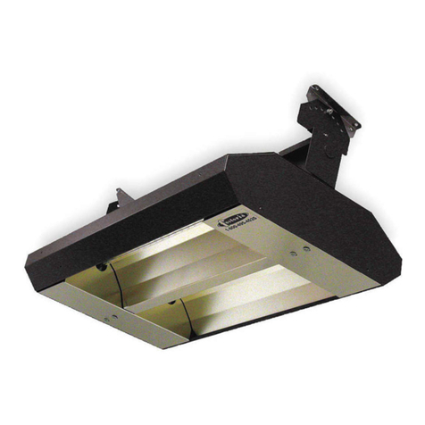
The Mitey Midget heater is available in five lengths, ranging
fr m 13 inches t 46 inches. Select fr m a wide variety f
wattage’s and v ltages, fr m 500W/120V t 3800W/577V.
These m dels have a heavy duty aluminum extrusi n with
a bright alumin
um insert, an aluminum h using, m unting
brackets f r permanent installati n r chain suspensi n,
and an end-t -
end wireway f r single end wiring and easy
installati n.
All m dels are UL and C-
UL (USA and Canada) Listed
under file #E32304, f r ind r c mm
ercial and industrial
c mf rt heat applicati ns.
Not for indoor residential use.
DESCRIPTION
MODEL
NUMBER
WIDTH LENGTH
(in.)
WATTS VOLTS
MM-13A
MM-18A
MM-18A
MM-24A
MM-24A
MM-24A
MM-33A
MM-33A
MM-46A
MM-46A
MM-46A
3-3/4”
13
18
18
24
24
24
33
33
46
46
46
500
1000
1000
1600
1600
1600
2500
2500
3000
3800
3650
120
208
240
208
240
277
480
577
480
577
480
SPECIFICATIONS
Read all instructions before using this heater.
1.
Make certain
that the p wer s urce c nf rms t the
electrical requirements f the heater. Disc nnect p wer
bef re installing r servicing. If the p wer disc nnect is ut
f sight, l ck it in the pen p siti n and tag it t prevent
unexpected applicati n f p wer. Fa
ilure t d s c uld
result in fatal electric sh ck.
WARNIN : DO NOT DEPEND UPON A THERMOSTAT OR
OTHER SWITCH AS THE SOLE MEANS OF
DISCONNECTIN POWER WHEN INSTALLIN OR
SERVICIN THE HEATER. ALWAYS DISCONNECT THE
POWER AT THE MAIN CIRCUIT BREAKER AS DES
CRIBED
ABOVE. FAILURE TO DO SO COULD RESULT IN FATAL
ELECTRIC SHOCK.
2.
This heater is intended ONLY f r permanent installati n in
acc rdance with the Nati nal Electric C de (NEC), all
applicable l cal c des and rdinances, and all secti ns f
this manual.
Any variance v ids the warranty and may
create unsafe c nditi ns. All wiring sh uld be d ne by a
qualified electrician, using c pper wire nly.
3.
This heater is intended f r general heating applicati ns
ONLY. It must NOT be used in p tentially danger us
l cati ns such as flammable, expl sive, chemical-
laden r
wet atm spheres.
IMPORTANT SAFETY INFORMATION
4.
Special attenti n must be given t any b nding (gr unding)
inf rmati n pertaining t this heater. T prevent the risk f
electr cuti n, the heater must be secu
rely and adequately
b nded. This sh uld be acc mplished by c nnecting a
c nduct r between the service panel and the green gr und
screw pr vided in the heater. T ensure a pr per b nd, the
b nding means must be tested by a qualified electrician.
5.
D n t ins
ert fingers r f reign bjects int the heater. D n t
bl ck r tamper with the heater while it is in perati n. D n t
t uch heater while it is in perati n r just after it has been
turned ff, as s me parts may be h t en ugh t cause injury.
6.
D n t a
ttach ductw rk t this heater r attempt t use it as a
make-
up air heater. Such use v ids the warranty and may
create unsafe c nditi ns.
7.
In cases where pr perty damage may result fr m malfuncti n
f the heater, a back-
up system r a temperature alarm
sh uld be used.
CAUTION:
Check branch v ltage. Heaters sh uld be perated at
v ltages n higher than the heating elements and the heater are
designed f r. (L wer v ltages, h wever, p se n pr blem ther
than a l ss f wattage).
ELECTRIC INFRARED HEATER
MITEY MIDGET
MODEL & PART NO.:
MM-13A (04440102)
MM-18A (04427602)
MM-24A (04495402)
MM-33A (04427202)
MM-46A (04420302)
OPERATION
OPERATION OPERATION
OPERATION
–
––
–
INSTALLATION
INSTALLATION INSTALLATION
INSTALLATION
–
––
–
PARTS MANUAL
PARTS MANUAL PARTS MANUAL
PARTS MANUAL
If y u have questi ns ab ut the
pr duct y u have purchased r w uld
like t leave us feedback please
c ntact us via ur website
www.f st riaindustries.c m
r by calling 1-800-495-4525.
Issue Date: 10-02-98 Rev. Date: 11-03-08 Rev. Level: 09 ECN N/A OIPM P/N 3420308 Page 2 f 4
CAUTION:
DISCONNECT POWER BEFORE
INSTALLIN OR REPLACIN LAMPS. THESE
LAMPS CAN AND SHOULD BE INSTALLED PRIOR
TO MOUNTIN HEATER.
T insert quartz lamp:
1
Rem ve the 4 sheet metal screws (2 each end) that
h ld fixture end caps in place.
2
Carefully wrap the he
ating element pigtail cl ckwise
ar und the terminal screws (see Figure 1). NOTE:
Cut excess pigtail wire ff at the terminal t prevent
the lead wire fr m t uching metal parts. Av id
handling quartz glass as much as practical. Quartz
sh uld be wiped ff with a clean cl th.
3
Tighten terminal screws (see Figure 1).
CAUTION:
Do not draw pigtail so tight that pressure is put
on the heating element. Maintain a partial loop
(or looseness) in the pigtail.
4
Replace the end caps using the screws rem ved in
Step 1
.
LAMP INSTALLATION
.
Always disconnect the heater from the power source
before performing any service or maintenance.
Peri dically
clean the reflect r with a dampened s ft cl th, using a mild
detergent. Rinse with water and wipe dry with a clean, s ft cl th.
1. Select appr priate kn ck ut n the terminal b x and
install the 6" c nduit nipple and splice b x
(b th cust mer supplied).
2. Place silic ne wire leads (18" free length pr vided)
fr m the terminal b x thr ugh the cust mer pr vided
c nduit, and c nnect the supply wiring inside the
cust mer pr vided splice b x. (See Figure 2 bel w)
3. F ll w l cal and nati nal electric c des.
4. Do not use the heater as a field-wiring compartment.
WIRING
1/2" slack on pigtail
Cut off excess
Wrap pigtail
clockwise
around screw
Figure 1.
Splice box
(by cust.)
" conduit nipple
(by customer)
Figure 2.
POSSIBLE LAMP FAILURE
The heating elements used in this product can be damaged by
contamination (salt deposits fr
om perspiration or coastal air) on
the surface of the quartz sleeve. At high temperatures, these
salts will cause the quartz to become porous and leak allowing
air to come in contact with the tungsten element. When this
occurs, the element will burn out quickly and the quartz tube
can break. The instructions below must be followed.
• Always wear cotton or latex gloves when installing
or replacing elements.
• Always clean the quartz tube with an alcohol-
moistened soft cloth before using the heater.
• henever contamination (milky white appearance
on quartz tube) is observed, the element must be
immediately replaced.
OPTIONAL LAMPGUARD INSTALLATION
MAINTENANCE
L p Supp rt clip ar und sh rt cr ss wire as sh wn with l ng
wires away fr m clip.
Supp rt Clip
Lampguard
L ng
wire
1. Rem ve (2) screws and endcap.
2. Insert wireguard as sh wn.
3.
Replace end cap and screws.
4.
Insert ends f clip under edges f extrusi n.
Lampguard
Supp rt Clip
Screw
End cap Extrusi n
Issue Date: 10-02-98 Rev. Date: 11-03-08 Rev. Level: 09 ECN N/A OIPM P/N 3420308 Page 3 f 4
SYMPTOM
POSSIBLE CAUSE(S)
CORRECTIVE ACTION
Element d es n t energize.
N t en ugh heat.
T much heat.
1. Defective element.
2. Impr per c nnecti n.
3. Pigtail l se fr m s cket
c nnecti n.
1. Heater t small f r applicati n.
2. Heater m unted t high r t far.
1. Heater t large f r applicati n.
2. Heater m unted t l w r t
cl se.
1. Replace element.
2. Check c nnecti n t utlet.
Check p wer.
3. Rewind pigtail n s cket.
1. Add additi nal heaters.
2. Decrease m unting height r
distance.
1. Replace with smaller heater.
2. Increase m unting height r
distance.
"A" dimensi n indicates exact spacing
between m unting brackets. (See sketch
at right.)
REPLACEMENT PARTS LIST and EXPLODED VIEW
TROUBLESHOOTING CHART
Model
MM
-
13A
MM
-
18A
MM
-
24A
MM
-
33A
MM
-
4 A
"A" Dim.
4"
9"
15"
24"
37”
2 1/2
A
M unting brackets extend 1"
fr m the t p f the end b xes.
Kn ck uts are 7/8" diameter t
accept 1/2" c nduit.
4
1
7
18
5
11
9
2
19
20
8
15
14
3
10
1
3
10
12
8
7
9
11
MOUNTING DIMENSIONS
Issue Date: 10-02-98 Rev. Date: 11-03-08 Rev. Level: 09 ECN N/A OIPM P/N 3420308 Page 4 f 4
The bligati n f F st ria Industries, Inc. under the terms
f this warranty, shall be t
supply a new part, repair f defective part, r a refund, at the c mpany’s pti n with n
c st t wner f r the new r repaired part. Such parts are t be returned t the fact ry, r
such ther l cati n as the c mpany may desig
nate. This warranty d es n t bligate
F st ria Industries, Inc. t bear the c st f lab r in replacing any assembly, unit r
c mp nent part there f, n r d es the c mpany assume any liability f r sec ndary
charges, expenses f r installing r rem val, r any
ther c nsequential l sses. The
c mpany’s maximum liability shall n t in any case exceed the list price f r the pr duct
claimed t be defective.
The warranty shall n t apply t any pr duct r parts f pr ducts that have been repaired r
altered utside f Seller’s fact ry in any manner. Warranty is v id n pr ducts that have
been determined t have been subjected t misuse, negligence r accident r which have
been used in a manner c ntrary t Seller’s instructi ns.
The warranty herein set f rth is in lieu f all ther warranties express
ed r
implied.
F st ria Industries, Inc. f F st ria, Ohi 44830, warrants its pr ducts t the
wner against defects in material and w rkmanship f r a twelve (12) m nth
peri d under n rmal use and service f ll wing date f manufacture r installati n
when
pr f f such is pr vided t seller.
This Warranty requires that the wner, r his agent, install the equipment in
acc rdance with the Nati nal Electrical C de, any ther applicable heating r
electrical c des and the manufacturer’s installati n instruct
i ns. It further requires
that he perf rm reas nable and necessary maintenance n the unit. The
c mpany is n t liable f r abuse r misuse f pr duct as may be finally
determined by the c mpany.
FOSTORIA INDUSTRIES, INC. – 1200 N rth Main Street - F st ria, Ohi 44830-1911 - (419) 435-9201
WARRANTY
REF.
NO.
1
2
3
4
5
6
7
8
9
10
11
12
13
14
15
16
17
18
19
20
DESCRIPTION
H using end
Lamp h lder (pri r t Aug 2006)
Lamp h lder (after Aug 2006)
Spring h se clamp
End cap
Screw PHD P 10-32 X 3/8 lg.
Washer l ck external t th #10
(pri r t Aug 2006)
Washer l ck external t th #10
(after Aug 2006)
Hex nut #10-32(pri r t Aug
2006)
Hex nut #10-32(after Aug 2006)
S cket assy. w/brass centered
Screw HHM 3/8-16 X 1/2 lg.
Hex nut 3/8-16
Screw HHD S #6 X 3/8 Type B
(pri r t Aug 2006)
Screw HWH #8-18 7/8(after
Aug 2006)
Screw PHD P 10-32 X 1 lg.
Wire assembly 12 Ga. SF-2 Bl.
Extrusi n
Reflect r
Aluminum tubing 3/8 OD
Wire assembly 12 Ga. SF-2 Bl.
Wire assembly 12 Ga. SF-2 Gr.
PART NUMBER
8509100
8509200
8509800
2400539
8509000
3401539
3466039
3466039
3405239
3405239
8500001
3474339
3494039
3400439
2465000
3401939
See Table A
See Table A
See Table A
See Table A
3160633
3160704
QTY.
2
2
2
2
2
1
5
1
5
1
2
2
2
4
4
4
1
1
1
1
1
1
Electric Infrared Element Information
When ordering a quartz lamp, be sure to designate
whether your application requires a Horizontal or Ve
rtical
quartz lamp model number. Non-
vertical burning quartz
lamps must be horizontally mounted to avoid
premature
burnout.
M del
Series
MM-
13A
MM-
18A
MM-
24A
MM-
33A
MM-
46A
Item #13
Part N .
3160607
3160610
3160620
Item # 14
Part N .
9721215
9721821
9722730
9724043
Item #15
Part N .
8049001
9720712
8049002
8049003
8049004
8049005
Item #16
Part N .
8509601
8509602
8509603
8509604
8509605
3160603
3160604
Table A

This manual suits for next models

10

Other Fostoria Heater manuals

Fostoria FSS Series User manual

Fostoria

Fostoria FSS Series User manual

Fostoria FFH-912B Specification sheet

Fostoria

Fostoria FFH-912B Specification sheet

Fostoria OCH–46-120V User manual

Fostoria

Fostoria OCH–46-120V User manual

Fostoria 222 Series User manual

Fostoria

Fostoria 222 Series User manual

Fostoria CH-6424-1C User manual

Fostoria

Fostoria CH-6424-1C User manual

Fostoria PCH-48C User manual

Fostoria

Fostoria PCH-48C User manual

Fostoria RPH-208-A Specification sheet

Fostoria

Fostoria RPH-208-A Specification sheet

Fostoria OCH-SS series User manual

Fostoria

Fostoria OCH-SS series User manual

Fostoria FSA Series User manual

Fostoria

Fostoria FSA Series User manual

Fostoria SUN-MITE RPH-240-A User manual

Fostoria

Fostoria SUN-MITE RPH-240-A User manual

Fostoria MTM 222 User manual

Fostoria

Fostoria MTM 222 User manual

Popular Heater manuals by other brands

VITAE DIR-1300-R Instructions for installation and use

VITAE

VITAE DIR-1300-R Instructions for installation and use

VOGEL&NOOT VONARIS VSV installation instructions

VOGEL&NOOT

VOGEL&NOOT VONARIS VSV installation instructions

VOGEL&NOOT NERO Assembly and operating manual

VOGEL&NOOT

VOGEL&NOOT NERO Assembly and operating manual

Argo MOOD operating instructions

Argo

Argo MOOD operating instructions

Life Smart LS-1000X-4C owner's manual

Life Smart

Life Smart LS-1000X-4C owner's manual

Bromic Heating Tungsten Smart-Heat Installation, instruction and  service manual

Bromic Heating

Bromic Heating Tungsten Smart-Heat Installation, instruction and service manual

ORIGO FH-T48P instruction manual

ORIGO

ORIGO FH-T48P instruction manual

ISAN MAGIC MIRROR manual

ISAN

ISAN MAGIC MIRROR manual

EOS VITAE Assembly Instruction and instructions for use

EOS

EOS VITAE Assembly Instruction and instructions for use

Beper RI087 use instructions

Beper

Beper RI087 use instructions

Rointe Lyon electric pro instruction & installation guide

Rointe

Rointe Lyon electric pro instruction & installation guide

nedis HTFA16GY manual

nedis

nedis HTFA16GY manual

Infiniton GPH-20W user manual

Infiniton

Infiniton GPH-20W user manual

AUTOTERM Air 4B Operation manual

AUTOTERM

AUTOTERM Air 4B Operation manual

Orbegozo BP 0204 instruction manual

Orbegozo

Orbegozo BP 0204 instruction manual

Rinnai RHE1S40N Installation and operation manual

Rinnai

Rinnai RHE1S40N Installation and operation manual

HeatStar HS115SF Operating instructions and owner's manual

HeatStar

HeatStar HS115SF Operating instructions and owner's manual

TZS First AUSTRIA FA-5570-2 instruction manual

TZS First AUSTRIA

TZS First AUSTRIA FA-5570-2 instruction manual

manuals.online logo
manuals.online logoBrands
  • About & Mission
  • Contact us
  • Privacy Policy
  • Terms and Conditions

Copyright 2025 Manuals.Online. All Rights Reserved.