manuals.online logo
Brands
  1. Home
  2. •
  3. Brands
  4. •
  5. Claudgen
  6. •
  7. Heater
  8. •
  9. Claudgen HE7010 Manual

Claudgen HE7010 Manual

44000044 Iss 07
Consort Equipment Products Ltd
Registered Office: Thornton Industrial Estate
Milford Haven, Pembrokeshire, SA73 2RT
Tel: 01646 692172 Fax: 01646 695195
BS EN ISO 9001 Registered Company No
FM12671
INSTALLATION, OPERATION AND MAINTENANCE INSTRUCTIONS FOR
H
EAT
-Z
ONE
F
AN
H
EATER
Catalogue Numbers HE7010 3 kW 230/240 V HE7020 4.5 kW 230/240 V
HE7030 3 kW 220 V HE7040 4.5 kW 220 V
HE7060 2kW 240 V
PLEASE RETAIN THIS LEAFLET FOR FUTURE MAINTENANCE
MODEL
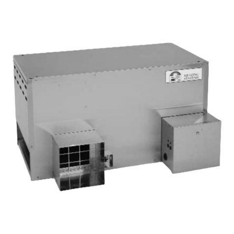
Heat-Zone is a quiet Fan Heater designed for Co ercial and
Industrial situations, and is suitable for ounting on the wall.
The Heat-Zone incorporates a tangential flow fan and the unit is
designed to operate in free air conditions. It is i portant that
there should be no restriction on the free flow of air through the
unit. When installed the top of the heater case should be a
ini u of 200 fro the ceiling.
PROTECTION
The unit is protected in the event of fan failure, or an
obstruction of the free airflow, by a single ther al PTC Self
Hold Cut-out. Having tripped the PTC Cut-out re ains open,
effectively switching off the heating ele ents, as long as ains
power is available inside the appliance. The PTC Cut-out will
only reset when the appliance is switched OFF and allowed to
cool for at least 20 inutes.
MOUNTING
The nor al ounting height is 2.3 above the floor, although
this will depend to so e extent on the situation. The unit
should be ounted at least 450 below ceiling. The heater
can be arranged to blow air at any angle, fro horizontal to
vertically downwards, subject to the conditions entioned
below. It is suggested that an angle of 45 deg is a convenient
starting point when setting up the unit. It ust always be
installed with the axis of the otor horizontal. Failure to ensure
this will result in excessive bearing wear and pre ature failure.
A ounting bracket is provided for ounting to a wall.
The heater should not be ounted in situations where it ay be
subject to conditions of excessive hu idity or the at osphere is
corrosive.
INSTALLATION
To the unit connect a suitable length of 3 or 4 core flexible
cable (1.5
2
for 2 and 3 kW or 2.5
2
for 4.5 kW) to the
input ter inal block. (3 core for ‘on/off’ control, 4 core for
‘fan only and fan heater’, see Electrical Connection).
Loosen ounting screws, allowing the ounting bracket to be
re oved fro the unit. Making sure that the ounting bracket
is horizontal, fix the bracket to the wall using 3 x No 8 wood
screws.
Place the unit on the ounting bracket ensuring the washers are
spaced as on diagra .
Tighten screws to hold the unit at the required angle.
ELECTRICAL CONNECTIONS
These units are suitable for connection to a 230/240V 50Hz
single phase ac supply (220 V for Models HE7030 & HE7040). The
units consu e 2Kw (HE7060) & 3kW (HE7010 & HE7030) or 4.5
kW (HE7020 & HE7040) of electrical power when the fan and
heater are in operation.
To connect a supply to the heater the curved top cover first
needs to be re oved. Looking directly at the output grille the
top cover is secured by two screws which are located at the
upper left and right of the outlet grille. Once the 2 screws are
re oved the curved top cover can be re oved by lifting it up
and away fro the output grille, then lifting off the cover fro
the two slot hinges located at the opposite side to the two
screws. The input ter inal block, arked NFH, is fitted at the
left hand side of the unit looking fro above (at the opposite
end to the fan otor.
For safety reasons, a sound earth connection MUST ALWAYS be
ade to the unit before being put to use.
The Heat-Zone can be connected in a nu ber of ways depending
on the for of control required. Whichever ethod is used, a
double-pole isolator switch should be included in the
installation.
44000044 Iss 07
SIMPLE ON/OFF CONTROL
If it is desired to control the Fan and the Heat together, then
connect the live supply wire to the ter inal arked ‘F’, the
neutral wire to the ter inal arked ‘N’, and the earth wire to
the earth ter inal. The ‘Link’ is incorporated in the unit when
it leaves the factory.
SEPARATE FAN AND HEAT CONTROL
If it is desired to control the Fan and the Heat separately, use
the HE7001 Re ote Control Unit which is available separately.
The HE7001 Re ote Control Unit co prises of two double pole
20 a p rocker switches in a surface ounting box 147 x
87 x 39 deep.
Re ove the ‘Link’ between ter inals ‘F’ and ‘H’ inside the
heater. The switch box is supplied with links for use with the
heaters as shown in Fig 1. Make connections fro the ains to
the switch and fro the switch to the heater, including the link
interconnection between the switches as indicated in Fig 1.
Fig 1.
The switch cover plate is arked as indicated, and the
interconnection between the switches is ade to ensure that
the heater cannot be connected without the fan in operation.
MAINTENANCE
ALWAYS ENSURE THAT THE MAIN EXTERNAL ELECTRICITY SUPPLY
IS SWITCHED OFF BEFORE ATTENDING TO THE SERVICING OF THE
UNIT.
To obtain the best results fro Heat-Zone it is necessary to
avoid any build-up of dust or dirt within the unit or on the air
inlet grille. For this reason the unit should be cleaned regularly,
paying particular attention to the re oval of dirt build-up on
the back of the fan rotor blades.
The re oval of dust and dirt is best achieved using a soft brush.
THERMOSTAT CONTROL
The connections are the sa e as in Fig 3a below, except that
the ‘live’ connection is taken through a roo ther ostat. This
ther ostat ust be capable of switching 13 a ps ac at 240
volts.
IN ALL CASES, THE UNIT SHOULD BE WIRED IN ACCORDANCE
WITH IEE REGULATIONS FOR THE ELECTRICAL EQUIPMENT OF
BUILDINGS.
TO RESET THE PTC SELF-HOLD CUT-OUT
DO NOT ADJUST BY HAND ANY INTERNAL COMPONENTS
a) The Cut-out is reset by switching OFF ains power to the
appliance.
b) Allow the appliance to cool for 20 inutes.
c) Restart, switch ON the appliance. If the Cut-out trips again
a qualified electrician should be consulted.
TO REMOVE THE FAN HEATER ASSEMBLY
a) Re ove the top cover as described under the heading
‘Electrical Connection’.
b) Disconnect the supply wires to the input ter inal block and
earth post.
c) Unscrew the bush holding the ter inal block asse bly to
the ain case.
d) Re ove the 4 nuts and washers holding the fan heater
asse bly in place.
e) The fan heater asse bly, ter inal block and internal wiring
can now be re oved.
The asse bly is replaced by carrying out the above operations in
the order e) to a).
SPARES
It is essential when ordering spares or replace ent parts to
state the odel nu ber and serial nu ber on the rating place
fixed to the top of the unit.
In the interest of progress the Co pany reserve the right to vary
specifications fro ti e to ti e without notice. The aterial
listed is offered subject to the Co pany’s General Conditions of
Sale, a copy of which ay be obtained by request.

This manual suits for next models

4

Other Claudgen Heater manuals

Claudgen HE6351 Manual

Claudgen

Claudgen HE6351 Manual

Claudgen HE6137SL Use and maintenance manual

Claudgen

Claudgen HE6137SL Use and maintenance manual

Claudgen RCT250SL Use and maintenance manual

Claudgen

Claudgen RCT250SL Use and maintenance manual

Claudgen HE7237 User manual

Claudgen

Claudgen HE7237 User manual

Claudgen HE7230W Installation and operating instructions

Claudgen

Claudgen HE7230W Installation and operating instructions

Claudgen SCREENZONE RAC1306 User manual

Claudgen

Claudgen SCREENZONE RAC1306 User manual

Claudgen SCREENZONE RAC1306 User manual

Claudgen

Claudgen SCREENZONE RAC1306 User manual

Claudgen HE8320RF Manual

Claudgen

Claudgen HE8320RF Manual

Claudgen HE7402RF Manual

Claudgen

Claudgen HE7402RF Manual

Claudgen HE7237 Manual

Claudgen

Claudgen HE7237 Manual

Claudgen CH06CSi User manual

Claudgen

Claudgen CH06CSi User manual

Claudgen CA1509S Original operating instructions

Claudgen

Claudgen CA1509S Original operating instructions

Claudgen HE6502 Manual

Claudgen

Claudgen HE6502 Manual

Claudgen HE7402-31 Manual

Claudgen

Claudgen HE7402-31 Manual

Claudgen HE7010SL Use and maintenance manual

Claudgen

Claudgen HE7010SL Use and maintenance manual

Claudgen RAC1509 User manual

Claudgen

Claudgen RAC1509 User manual

Claudgen CA1309S Original operating instructions

Claudgen

Claudgen CA1309S Original operating instructions

Claudgen HE7245 User manual

Claudgen

Claudgen HE7245 User manual

Claudgen ScreenZone CA2015S User manual

Claudgen

Claudgen ScreenZone CA2015S User manual

Claudgen HE8326-33 Manual

Claudgen

Claudgen HE8326-33 Manual

Claudgen HE7237SL User manual

Claudgen

Claudgen HE7237SL User manual

Claudgen HE7230SL User manual

Claudgen

Claudgen HE7230SL User manual

Claudgen HE7230 User manual

Claudgen

Claudgen HE7230 User manual

Claudgen CA1309S Manual

Claudgen

Claudgen CA1309S Manual

Popular Heater manuals by other brands

Jocel JET-014832 instruction manual

Jocel

Jocel JET-014832 instruction manual

Vie Air VA-708B owner's manual

Vie Air

Vie Air VA-708B owner's manual

VonHaus 2514041 instruction manual

VonHaus

VonHaus 2514041 instruction manual

PSI 1450 Series Owner's manual and instructions

PSI

PSI 1450 Series Owner's manual and instructions

Nortek C8QV Series installation instructions

Nortek

Nortek C8QV Series installation instructions

Clarke XR60 Operating & maintenance instructions

Clarke

Clarke XR60 Operating & maintenance instructions

Mi-T-M MH-0400-0M10 Operator's manual

Mi-T-M

Mi-T-M MH-0400-0M10 Operator's manual

Unold 86140 Instructions for use

Unold

Unold 86140 Instructions for use

Shini STM Series manual

Shini

Shini STM Series manual

Dimplex OFX750 Operating and installation

Dimplex

Dimplex OFX750 Operating and installation

Adler Europe AD 7731 user manual

Adler Europe

Adler Europe AD 7731 user manual

Ruby ASCANI instructions

Ruby

Ruby ASCANI instructions

Eterna OILH211TIM installation instructions

Eterna

Eterna OILH211TIM installation instructions

TSI Instruments 854033 quick start guide

TSI Instruments

TSI Instruments 854033 quick start guide

Zehnder Rittling Bisque 4FE-40-55/F Fitting instructions

Zehnder Rittling

Zehnder Rittling Bisque 4FE-40-55/F Fitting instructions

R.E Williams Contractor A716 user manual

R.E Williams Contractor

R.E Williams Contractor A716 user manual

HOMCOM 820-249V70 Assembly & instruction manual

HOMCOM

HOMCOM 820-249V70 Assembly & instruction manual

Fagor AFL-60T Instructions for use

Fagor

Fagor AFL-60T Instructions for use

manuals.online logo
manuals.online logoBrands
  • About & Mission
  • Contact us
  • Privacy Policy
  • Terms and Conditions

Copyright 2025 Manuals.Online. All Rights Reserved.