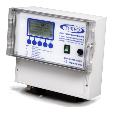
Turbo EIT Series User manual

TURBO
s.r.l.
Electronic Control Systems for Dust Collectors
e-mail: info@turbocontrols.it web: www.turbocontrols.eu
TEL. +39 (0)362 574024 FAX +39 (0)362 574092
BUILT-IN ECONOMISER
EIT SERIES
1 to 16 solenoid valves
User Manual
01/02/2021
Manual Release 1.03
Hardware Release 4.00

1
General Description
The EIT control unit is an electronic device for controlling pneumatic cleaning of the
Industrial Dust Collector Systems.
The pressure transducer mounted on the unit measures the differential pressure, allowing an
accurate analysis of the filter clogging status.
The control unit has 2 relay contacts, to signal alarm events, a 4-20mA self-powered output,
useful for transmitting the pressure value read to a remote device, and a large graphical
LCD, which displays the operating status and, through a membrane keypad, allows
configuration of the general parameters.
Components
·Main body of the die-cast aluminium casing.
·On-board electronics
·Multilingual alphanumerical keyboard and LCD
·Transparent and flexible protective PVC membrane, which allows IP65 protection.
·Cabinet wall fixing kit
·Support bracket for circuit board
·Item fixing bolts
·Front ON-OFF power supply switch
Technical features and general operation
·Power supply voltage 115-230Vac ± 10% 50-60 Hz, which can be selected via hardware
jumpers (Inputs optional: 24Vac, 24Vdc).
·Solenoid valves output voltage 24Vdc, 24-115-230Vac, which can be selected via hardware
jumpers.
·Backlight LCD (visual area 72.0 x 40.0 mm).
·Two relays with potential-free contact, which can be associated to the desired alarm event.
·Operating mode which can be selected from MANUAL, AUTOMATIC, AUTOMATIC with forced
cycle, PROPORTIONAL.
·Pressure is measured in kPa, (WC inches, mmH20, daPa optional).
·Cleaning function with fan off (Post-Cleaning) with fan dP threshold setting or from input
contact.
·Control unit work total hour meter.
·Partial hour meter for maintenance signals, which can be activated and with programmable
hourly threshold.
·Maximum dP alarm (clogged filter).
·Minimum dP alarm (broken sleeve/cartridge) with the possibility of deactivation of the
function.
·Solenoid valve malfunctioning alarm.
·Filtering elements maintenance alarm, with the possibility of deactivation of the function.
·Input contact for functions cut-off of the control unit (can be used as compressed air
presence consent).
·Precoating function with possibility of deactivation.
·Active output 4-20 mA (self-powered), proportional to the dP reading, for transmission to
remote reading device.
·Solenoid valve manual activation test function.

2
Electrical Features
Power Supply:
·115Vac ± 10% 50-60 Hz –25W
·230Vac ± 10% 50-60 Hz –25W
·24Vac ± 10% 50-60 Hz –25W (optional)
·24Vdc ± 10% –25W (optional)
Output voltage selectable for:
·115Vac Maximum Load 25W
·230Vac Maximum Load 25W
Inputs and outputs:
·Cleaning remote enabling contact input.
·Fan contact input for post-cleaning.
·Active output 4 –20 mA for pressure dP remote transmission.
The solenoid valves connected to the control unit are the normally closed type.
Their activation opens the jet of air.
Alarm Relays
The two alarm relays have potential-free contacts (no voltage) at terminals 4-5 and 6-7 of the
terminal board.
Maximum permissible load: 3A @ 250Vac, 2A @ 24Vac, 2A @ 24Vdc.
Fuses
1 x 1 A @ 115Vac. 1 x 1 A @ 230Vac.
1 x 3 A @ 24Vac. 1 x 3 A @ 24Vdc.
Operating Temperature
-10 °C/+55 °C
Storage Temperature
-20 °C/+60 °C
Timer features:
Pulse Time (Valve opening)
50 msec ÷ 5 sec.
Pause time (interval between valves opening)
1 sec. ÷ 999 sec.
Differential Pressure Meter
Measurable pressure range: 0 ÷ 4 kPa 0 ÷ 10 kPa
Maximum Pressure Applicable: 16 kPa (0.16 bar) 40 kPa (0.40 bar)
Warning! Higher pressures
will damage the device.
Do not connect clogging
measuring tubes to the
compressed air circuit.
Warning! Read the section on
installation before connecting
the device.

3
Warning Symbols Used in the Manual
The indications regarding safety are highlighted using the following symbols:
Attention - Danger Warning - Generic
Risk –Hazard Electric Current
Dispose of according to the WEEE Waste Electrical and
Electronic Equipment Directive
Installation Regulations and Warnings
ÜProtect the equipment from direct sunlight.
ÜDo not position the device near heat sources and electromagnetic fields.
ÜMount the equipment to the wall at least 60 cm from the floor.
ÜIn a clearly visible place, which is easy to reach.
ÜConnect the equipment to supply lines different to those used for motor drives or other
large power devices that could generate network disturbances or instability.
ÜThe appliance electric power supply must be protected by a 230Vac~ 30 mA differential
circuit breaker and a 230Vac~ 10 A bi-polar magnet circuit breaker, positioned in a place
that is easy to reach.
ÜBefore intervening on the appliance to perform any operation, deactivate the
magnet circuit breaker.
ÜFor electrical operations, always remove the voltage and wait 30 seconds for the
internal capacitors to discharge before opening the container. When finished, close the
device before turning on power.
ÜMake sure you are in a safe atmosphere before using the equipment for any type of
operation.
ÜUse flame-proof cables with minimum section of 0.75 mm² certified and compliant with
IEC60227 or IEC60245 to connect the power supply voltage.
ÜUse flame retardant cables with a minimum section of 0.75 mm² for all input control
signals.
ÜUse flame retardant cables with a minimum section of 0.75 mm² for signal relay contacts.
ÜUse cables with a minimum section of 0.34 mm² for all solenoid valve control signals.
ÜThe protective earth cable must be yellow/green.
ÜThe protective earth cable must be connected first.
ÜThe yellow/green cable must only be used for earthing.

4
ÜThe cable glands must be chosen according to the diameter of the cable to be used.
ÜThe tightness of the cable gland is guaranteed by the compression of the rubber seal
that tightens on the outer diameter of the cable.
ÜThe size of cable and cable gland must ensure that a power cord traction is not acting on
the terminals.
ÜThe terminal block must not be the point of mechanical anchoring of the conductors.
ÜThe cable gland M16 supplied on request, has cable diameter minimum of 4 mm and a
maximum of 8 mm, with clamping nut by 19 mm.
ÜAny use not described in this user instruction manual or incorrect use of the device may
cause damage to the device or to the devices connected to it.
ÜFurthermore, incorrect use or tampering with the device may cause injury.
ÜWaterproofness of the casing is guaranteed when the flap is closed.
ÜMake sure that rigid or flexible ducts used for wiring, if any, do not fill up with water or
other liquids.
ÜDo not make holes not protected on the container or protected by accessories with
protection degree lower than that of the housing of the control unit.
ÜCut off power supply immediately if water is found in the casing.
ÜIf the control unit is used in ways not specified by the manufacturer, the protection
provided by the device may be impaired.
ÜThe Control Unit does not release potentially toxic or harmful substances to the health
and the environment.
ÜNo part with dangerous voltage is normally accessible.
Do not use the economiser before reading
and understanding this manual.

5
Display and keyboard
A 5-key membrane keypad is placed on the front panel. This is useful for accessing control
unit functions. At power-on, the Control unit will show the product’s name and the installed
firmware version.
After the unit is switched on, the information about
the
operating status will appear on the display, such as the
pressure dP reading, the operating mode set, the cycle time
and the operating status.
By pressing the "MENU"
button, the user can access the
control unit configuration menu page.
In the menu page, by pressing the “
↑” and “↓” buttons, the
item desired can be highlighted.
Press the “OK”button to access the menu item highlighted
and display the parameters that can be modified.
The
“OK”button is also used to confirm choices or silence the
alarms, if present.
In the parameters page, by pressing the “
↑” and “↓” buttons,
the parameter to modify can be highlighted.
The value of a parameter can be modified
using the “+”and
“-”buttons.
By pressing the "EXIT" button, go back to the previous screen,
saving any modified parameters in the memory.

6
Main Menu
The menu and the individual functions in the same are organised as follows:
Base Settings
Default
Operating Mode
Manual (dP value displayed but not used)
Automatic
Automatic with forced cycle
Proportional
AUTOMATIC
Pulse time
Solenoid valve activation time
Values that can be set: 0.05 seconds –5.00 seconds step 0.01
seconds
0.20 sec
Pause Time
Cleaning pause between solenoid valves
Values that can be set: 001 sec –999 sec (step 1 sec) 20 sec
Number of
outputs
Number of connected outputs
Values that can be set: 001 –099 (step 1) 1
Start Threshold
Cleaning cycle Start Threshold
Values that can be set: 0.00 kPa –3.99 kPa (step 0.01) 0.80 KPa
Stop Threshold
Cleaning cycle Stop Threshold
Values that can be set: 0.00 kPa –3.99 kPa (step 0.01) 0.40 KPa
Advanced Settings
Default
Fan Mode
Fan on acknowledgement mode
Values that can be set: from contact –from dP dP
Fan Threshold
dP threshold for fan on acknowledgement
if
Fan Mode
= from dP
Values that can be set: 0.00 kPa –3.99 kPa (step 0.01)
0.10 KPa
PCC Cycles
Number of Post Cleaning cycles after the fan stops
Values that can be set: 01 –99 (step 1) 1
Pause in PCC
Pause between Post Cleaning valves during a cycle with the
fan off
Values that can be set: 001 sec –999 sec (step 1 sec)
10 sec
Precoating
Enabling the Precoating function
Values that can be set: 0 (disabled) –1 (enabled) 0
Precoating
THold
dP threshold for Precoating function end
Values that can be set: 0.00 kPa –3.99 kPa (step 0.01) 2.00 KPa
Enforced
Cycle in
Selection of minutes or hours for Forced Cleaning Cycle
interval. minutes
T Enf.cycle
Interval of time for Forced Cleaning Cycle selected in relation
to the choice made in “
Forced Cycle In”.
Values that can be set: 1 - 999 (step 1)
240 min.

7
Alarms
Default
Al. Maintenance
Enabling of the alarm on maintenance interval
Values that can be set disabled –enabled Disabled
Maint. interval
Maintenance interval expressed in tens of hours
Values that can be set: 001 –999 (step 1).
(example: 1=10h, 10=100h)
100 hours
Min DP alarm
Enabling of the Minimum dP Alarm function
Values that can be set: disable –enable Disabled
Min
DP
Thold Al.
Minimum dP Alarm Threshold for Broken Sleeve or Cartridge
Values that can be set: 0.00 kPa –3.99 kPa (step 0.01) 0.20 KPa
Max DP
Maximum dP Alarm Threshold,
Filter Clogging, signalling delayed by 20 seconds
Values that can be set: 0.00 kPa –3.99 kPa (step 0.01)
3.00 KPa
Exclude
EV
in SC
If the short circuited valve is set, it is excluded from the cycle.
Values that can be set: disable –enable Disable
Calibration / Test
Default
Volt. Output
Output voltage setting
.
Press “OK”button to access to configuration’s window. 24 Vac
Manual
Activation
Output manual activation for output individual test.
Values that can be set: from 1 to Number of Outputs Set 1
Zero dP
dP zero threshold
for pressure zero adjustment
Values that can be set: 0.00 kPa –3.99 kPa (step 0.01) 0.00 KPa
4mA calibr.
The 4mA output signal corresponds to the 0 kPa pressure.
Measure the current with a ammeter between Terminals 10 (-
)
and 11 (+) and, by pressing the “+”and “-“buttons, set the
value so that the current is 4.00mA.
250
20mA calibr.
The
20
mA ou
tput signal corresponds to the
kPa
full
-
scale
pressure. Measure the current with a ammeter between
Terminals 10 (-) and 11 (+) and, by pressing the “+”and “-“
buttons, set the value so that the current is 20.00mA.
250
Volt. Output (
from
Calibration / Test menu
)
Default
Volt. Output
(1)
Values that can be set:
24 Vdc, 24 Vac, 115 Vac, 230 Vac
Press “+”or “-“button to select the value of the output
voltage. Press “EXIT”to store the parameter’s value.
24 Vac
(1) Before settin g the output voltage, make sure that the valve voltage output configuration jumpers
have been positioned following indic ation on page 16 and coherent with the valu e to be set.

8
Counters
Default
Tot.hour count
Overall count
er
of the hours of activity of the device from
commissioning. 0
Maint.hour CT
Maintenance Hour
counter
, dependent on the operating
period of the fan. 0
Pulse Tot:
Overall count
er
of the
pulses
of activity of the device from
commissioning. 0
Set up Display
Default
Language
One of the six languages available can be selected: Italian,
English, French, German, Spanish, Portuguese. Italian
Contrast
Used to increase or decrease the contrast of
the screen.
20%
Lighting
Used to set duration of back
-
lighting. The parameter can be
set in ON-OFF-AUTO. ON
System Info
SW GUI
version
Software version of the user interface
(Graphical User Interface).
SW EIT
version
Software version of the EIT SW
main control unit.

9
Alarms
The control unit performs a series of checks during the ignition cycle and normal operation.
Below find descriptions of possible alarms and relative solutions:
Code
Description Operation
E01
Output voltage setting
set at 24Vdc
Vac jumpers detected
-
If 24Vdc is desired, switch the device off and move
the AC/DC jumpers to DC.
-
If 24Vac is desired, press OK, then press SET, set
the Output Voltage Setting
function using “+”and
“-”, select 24Vac and confirm using OK.
E02
Output Voltage Setting
set 24Vac
Vdc jumpers detected
-
If 24Vac is desired, switch the device off and move
the AC/DC jumpers to AC.
-
If 24Vdc is desired, press OK, then press SET, set
the Output Voltage Setting
function using “+”and
“-”, select 24Vdc and confirm using OK.
E03
Output Voltage Setting
set 24Vac or Vdc.
Voltage out of range detected.
- If a 24V valve is to be used,
switch the device off
and move the output voltage selection jumpers to
24V.
-
However, if the jumpers are in the correct
position, press OK and then SET, use “+”and “-
”to
select the Output Voltage Setting
function, set 115
or 230 as jumpers and press OK.
E04
Output voltage setting
set at 115Vac.
Voltage out of range detected.
-
If a 115V valve is to be used, switch the device off
and move the output voltage selection jumpers to
115V.
-
However, if the jumpers are in the correct
position, press OK and then SET, use “+”and “-
”to
select the F05, set 115 or 230 as jumpers and press
OK.
E05
Output voltage setting
set at 203V.
Voltage out of range detected.
-
If a 230V valve is to be used, switch the device off
and move the output voltage selection
jumpers to
230V.
-
However, if the jumpers are in the correct
position, press OK and then SET, use “+”and “-
”to
select the Output Voltage Setting
function, set a24,
d24 or 115 as jumpers and press OK.
E06
Solenoid Valve Current lower than the
minimum threshold or solenoid valve
disconnected.
Check the correct solenoid valve connection
signalled during the error. The alarm auto-
resets if
the condition is solved.
E07 Solenoid Valve Current higher than
maximum value.
Check the cor
rect solenoid valve connection
signalled during the error. The alarm auto-
resets if
the condition is solved.
Continue…

10
Code
Description Operation
E08
Short Circuit on one or more outputs.
Signalling of code E08 alternates with the
indication of the output of interest. It is
shown as Uxx, where xx is the number of
the output and the dP value.
Switch the device off and back on again, after
having verified the connections of the solenoid
valves.
E09
Maximum dP pressure value exceeded
dP Maximum Threshold Alarm, Filter
Clogging, detected for a period of time
exceeding 20 seconds.
Verify filtering elements status.
E10 Offset hardware of the dP sensor is out
of range.
The self-
calibration of the dP sensor has determined
a value that is out of range
. Disconnect the air pipes
and repeat the function. Whenever the alarm should
re-occur, ask for technical assistance.
E11 Maintenance interval has been reached.
Perform maintenance.
E12 Full scale value of the dP sensor has
been reached. Signalling is immediately.
Verify filtering elements status.
WARNING: Operation in this condition can damage
the device.
E13
dP minimum value alarm between dP
Threshold For Fan On Acknowledgement
and dP Minimum Threshold alarm for
broken sleeve or cartridge. The alarm is
generated with a fixed delay of 60
seconds.
Verify filtering elements status.
E14
Indicates that a valve in Short Circuit
has been excluded from the cycle.
Signalling of code E14 alternates with the
indication of the output short circuited. It
is shown as Uxx, where xx is the number
of the corresponding output.
An output is considered Short Circuited if
the error condition is maintained for 3
successive activations.
An activation without errors resets the
count.
Sw
itch the device off and back on again, after
having verified the solenoid valves system.

11
Operation Description
When the control unit is switched on, the LCD shows the SW version installed, while it
verified congruency of the settings memorised in EEprom and the positions of the voltage
selection hardware jumpers. Whenever there is a discrepancy between the settings, the
corresponding error code will be displayed (Ref. Alarms Table). Functionality of the control
unit will be limited to just modification of the parameters. The operator can switch off and
configure the jumpers correctly.
Manual Operating Mode
When MANUAL operating mode is set, the control unit will work as a programmable cycle
sequencer. The connected outputs will be activated at programmed time intervals. Activation
of the manual function is possible by accessing the configuration menu and setting the
operating mode in “Manual”.Consequently the “Pulse Time”and the “Pause Time”will set
between the triggers.
Automatic Operating Mode
By selecting the “Automatic”operating mode, the control unit will function autonomously,
performing pneumatic cleaning only of necessary. If the unit detects that filter clogging
exceeds the “Start Threshold”, it starts the cleaning cycle. If clogging drops below the “Stop
Threshold”,cleaning is suspended until the pressure rises again to a value above that set in
“Start Threshold”.
When cleaning is in progress, the times with which the unit performs cleaning are always
those set in “Pulse Time”and “Pause Time”.
Automatic Operating Mode with Forced Cycle
It operates in the same way as the automatic operating mode, with exception that a cleaning
cycle can be started with activation of the solenoid valves connected without having reached
the “dP Start Threshold”, after the “Cycle Time forced”is elapsed.
The forced cleaning interval can vary from 1-999 min/h and can be selected from the
“Forced Cycle In”and “Forced Cycle Time”functions.
Proportional Operating Mode
With the Proportional Mode, the control unit will operate in complete autonomy by initially
setting the “dP Start Threshold”, “Pulse Time”and “Pause Time”. Automatically, when the
Start Cleaning threshold is exceeded, the solenoid valves are activated in sequence.
If the dP threshold lowers by 15% at the end of an entire pulse cycle for the connected
solenoid valves, cleaning is suspended until the pressure rises over the dP Start Cleaning
threshold again. If the dP value does not drop by 15% under the Start Cleaning threshold,
the cycle time frequency is automatically reduced proportionately at each complete cycle of
connected solenoid valve pulses, until a cycle time between solenoid valves equal to 10
seconds is reached.
The minimum 10 second threshold was chosen to not stress air distribution by the
compressor connected to the filter.

12
Cleaning Function with Fan Off (PCC)
This function allows one or more cleaning cycles to be performed (the number of cycles is
defined in
“PCC Cycles”) when the fan is off. The status of the fan can be determined from
the status of the contacts 12-13 (contacts open = fan off) if “Fan Mode= from contact”, or
can be determined automatically with “Fan Mode = from dP”,when the dP pressure drops
below the threshold defined in “Fan Threshold”. The pulse time of the valves will always be
that defined in “Pulse Time”, while, in this case, the pause time is defined in “PCC Pause
Time”.
During cleaning, the display will show the “Final Cleaning (PCC)”message.
Selecting the Number Of Outputs
The number of solenoid valve outputs on which the control unit will run the cleaning cycle
can be selected. Cleaning is run in order from the first solenoid valve to the last. The total
number of valves can be set using the “Number of Outputs”function.
Pre-coating Function
This function allows the pre-coating function to be performed. Pre-coating is a filter element
treatment run with a powder called pre-coating powder. When “Precoating = enabled”,
conventional cleaning is suspended until the precoating threshold, defined in “Precoating
Threshold”is reached.
Zero dP calibration
This function enables to reset the dP metering with the fan turned off. Increase or decrease
the value using the “+”and “-”buttons.
This value will be subtracted from the value read by the dP sensor.
Self-Calibration of the dP Sensor.
This function enables to automatically reset the dP metering with the fan turned off. Both
pneumatic connections must be removed in order to perform the function.
Switch the control unit on, at the same time holding the first and third keys from the left
down, until the “dP”self-calibration in progress”message appears on the screen.
The unit will return to normal status after a few moments, after having automatically
completed calibration.
Keyboard lock
In main window, the user can lock the front keyboard pressing and maintain pressed the 5
th
key for at least 10sec. A “LOCK”message will be shown on the display to inform that the
keyboard was locked. No setting operations will be possible. To unlock the front keyboard,
the user needs to press and maintain pressed the 5th key for at least 10sec. The “LOCK”
message will disappear. The lock/unlock condition is permanently stored in control unit non-
volatile memory.

13
Control Board Connection Layout
Pressure Sensor dP + pressure input section dirty
dP + negative pressure input section clean

14
Input/Output Contacts
Input Terminal Description
Remote Enabling
Contact 14-15
Used to activate the control unit from remote; it
can be activated and deactivated from a
distance.
The control unit is supplied with a jumper on
the two terminals 14-15. Without this, it
switches on but does not perform any activity,
in stand-by for the contact to be closed.
Fan
Contact 12-13
When closed, it informs the control unit that the
plant has been started and is operating.
The control unit is supplied with a jumper on
the two terminals 12-13 to simulate plant
operation, as if the fan were on.
Output Terminal Description
Contact Alarm K1
(potential-free switch) 4-5
The relay is normally closed. It opens in the
case of alarms and with board off, without
power supply.
The following events open the relay:
Max dP reached.
Min dP reached.
E06-E08 Solenoid Valves Problem.
Maintenance interval reached.
If one of these events occurs, the relay
activates.
Contact Alarm K2
(potential-free switch) 6-7
The relay is normally closed. It opens in the
case of alarms and with board off, without
power supply.
The following event opens the relay:
Max dP reached.
dP Output
(4-20 20mA Current-loop)
11-10
Current
-
loop 4
-
20mA output, active.
It is used to transmit the pressure valve to a
remote device.

15
Terminals Table
Terminal
Description Terminal
Description
01 Input 115-230Vac 04 Relay switch alarm 01
02 Input 115-230Vac 05 Relay switch alarm 01
03 PE Protection Earth 06 Relay switch alarm 02
07 Relay switch alarm 02
03 Solenoid Valves PE Earth
30 Common Solenoid valve
31 Solenoid valve output 01 12 Fan Input
32 Solenoid valve output 02 13 Fan Input
33 Solenoid valve output 03 14 Consent Input
34 Solenoid valve output 04 15 Consent Input
35 Solenoid valve output 05
36 Solenoid valve output 06 10 Output 4-20mA -
37 Solenoid valve output 07 11 Output 4-20mA +
38 Solenoid valve output 08
39 Solenoid valve output 09
40 Solenoid valve output 10
41 Solenoid valve output 11
42 Solenoid valve output 12
43 Solenoid valve output 13
44 Solenoid valve output 14
45 Solenoid valve output 15
46 Solenoid valve output 16
If the economiser is in G2 version with reinforced transformer, two solenoid valves can be
connected in parallel to every terminal.
Fuses Table
Voltage Value
There is a fuse in proximity of the power supply terminals
on the main board, which can be replaced if necessary.
Use a time-lag fuse 5x20mm.
(see table on the left for the value).
230 V 1 A
115 V 1 A
24 Vdc / Vac 3 A

16
Power Supply Jumpers Configuration
115 Vac 230 Vac
Output Voltages Jumpers Configuration
115 Vac 230 Vac
24 Vac 24 Vdc

17
Installation and Dimensions
Dimensions in mm

18
Maintenance
Apart from the fuse, the control unit does not have replaceable parts. All
other repairs must be carried out by the manufacturer.
To clean dust and dirt from the surfaces, rub delicately with cotton or
another type of soft cloth soaked in a non-aggressive, non-abrasive
detergent. Use those for glass surfaces, do not use solvents or aromatic
compounds and do not clean using abrasive sponges.
Disposal
Do not disperse in the environment after use. Dispose of the product according to current
regulations for the disposal of electronic equipment.
This device is used in a dust collector system and, therefore, it is part of a fixed installation.
Warranty
The warranty has a duration of 2 years. The company will replace any electronic component
deemed defective exclusively at our workshop, except in the presence of contrary
agreements to be authorized by the company.
Exclusions from Warranty
The warranty is void in the case of:
·Signs of tampering and unauthorised repairs.
·Incorrect use of the equipment that does not comply with the technical data.
·Incorrect electrical connections.
·Failure to comply with the installation standards.
·Use beyond EC standards.
·Atmospheric events, lightning, electrostatic discharge, over voltages.
·Clogged air connections. Damaged tubes.

19
Troubleshooting FAQ
Fault Possible Cause Solution
The display does not
turn on Blown fuse.
Check the protection fuse on the power
supply.
Check that the supply voltage is present and
concordant with that required for the
equipment terminals 01, 02 and 03.
The outputs do not
activate
Incorrect output voltage
Wiring to the solenoid valves.
Check that the output voltage of the control
unit and of the solenoid valves agree.
Check the wiring between the economiser and
the solenoid valves.
Differential pressure
metering is not
correct.
Clogged air connections.
Damaged tubes.
Check that differential pressure metering is
0.00 kPa when the tubes are disconnected. In
that case, check that the connection tubes
between the equipment and the filter are not
clogged or damaged.
The cleaning cycle is
not performed
The Start Threshold is set too high,
therefore does not perform any
trigger.
Modify the start
pressure threshold or put the
economiser in Manual mode to check
operation.
Alarm messages
appear Check the alarm code against the table.
The alarms do not
activate the signalling
devices.
Errors in the wiring.
Lack of powering of the alarm
devices.
The
alarm devices must be powered by voltage
external to the economiser.
To activate them, the latter opens the relative
relay.
The post/cleaning
starts during
conventional cleaning.
Fan Threshold set is too high. Modify the Fan Threshold of post-cleaning by
lowering it to an acceptable value.
The post/cleaning
does not start when
the normal cleaning
cycle ends.
Fan Threshold set too low.
Check that with the fan off, the pressure
measured is lower than the Fan Threshold for
post-cleaning.
The economiser sets
sporadically.
Check that there is not an unfiltered
pulse load (punching machines,
welders, plasma cutters, etc.) on the
power line.
If necessary, install a filter on the economiser
power line.
With the fan off, the
display does not
show
0.0 kPa.
Incorrect Zero dP calibration.
Calibrate the Zero dP appropriately or run the
self/calibration function, explained in the
Operating paragraph.
TURBO
s.r.l.
Electronic Control Systems for Dust Collectors
e-mail: info@turbocontrols.it web: www.turbocontrols.eu
TEL. +39 (0)362 574024 FAX +39 (0)362 574092
Table of contents
Other Turbo Control Unit manuals
Popular Control Unit manuals by other brands

DOLD
DOLD SAFEMASTER PRO UG 6951 user manual

SMC Networks
SMC Networks EX250-SCF1-X200 Operation manual

Valmet
Valmet Flowrox PVEG Installation, operation and maintenance instructions

Rockwell Automation
Rockwell Automation Allen-Bradley DM2 Application Technique

ZyCast
ZyCast resi-linx RL-RF380 installation manual

Mitsubishi Electric
Mitsubishi Electric Q2MEM-1MBSN manual