TD-700 Laboratory Fluorometer Operating Manual
Page 9
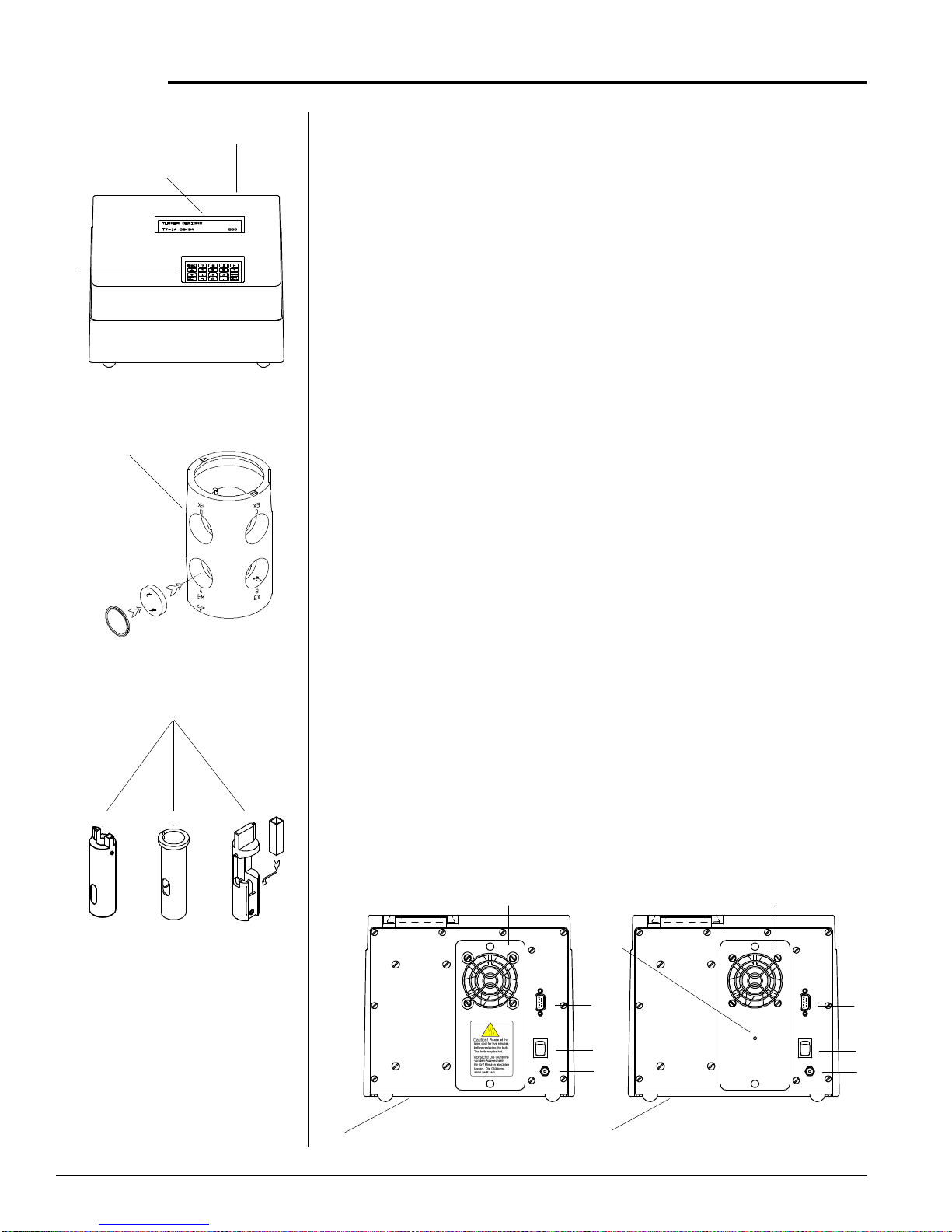
TD-700 Side View
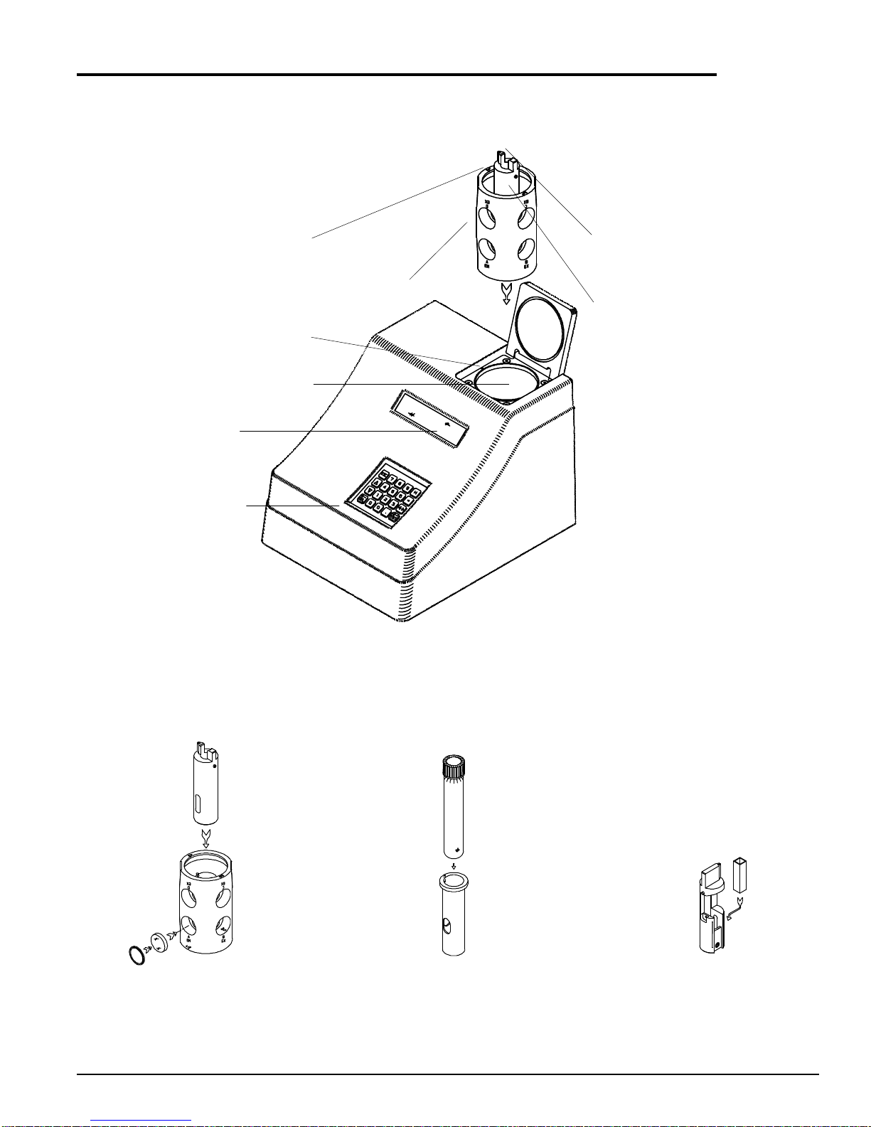
TD-700FilterCylinderAssembly
FilterCylinder
Assembly
III. Optical Filter Installation and Removal
TheTD-700Fluorometermusthavetwodifferentopticalfilterstooperate
correctly:anexcitationfilterandanemissionfilter.TD-700filtersareone-
inchdiameter,round,coloredglassorhighly-reflectiveglass.Thefiltersare
mountedintheFilterCylinderusingflexiblerubbero-rings.TheFilter
Cylinderisaccessedthrough the samplechamber.TheCylindercanhold
fourdifferentexcitation/emissionfiltercombinations,andislabeledonone
rim,“A” and “B”; andlabeled on the oppositerim, “C” and “D”. Eachof
these letters identifies a filter application set. Once the filter sets are
installedproperlyinthecylinder,changingfromoneapplicationtoanother
requiresasimplerepositioningofthecylinderandpossibly a lamp change.
ToremoveorinstallopticalfiltersintheFilterCylinder:
a. Removeanytesttubesorcuvettesandsampleadaptorsfromthe
instrument.Then,grasptheFilterCylinderbytherim and pull straight
up and out of the unit.
b. Locatethefilters(excitationandemissionfilters)fortheapplication
youwant to run. Filters aremarked on their rimwithan identification
number.
c. TheFilterCylinderhaseightopeningsforfourdifferentfiltersets.For
example,theopenings forfiltersetAare marked“A/EX”and“A/EM”;
filter set B is marked “B/EX” and “B/EM”. Select the A, B, C, or D
positions to install the filters.
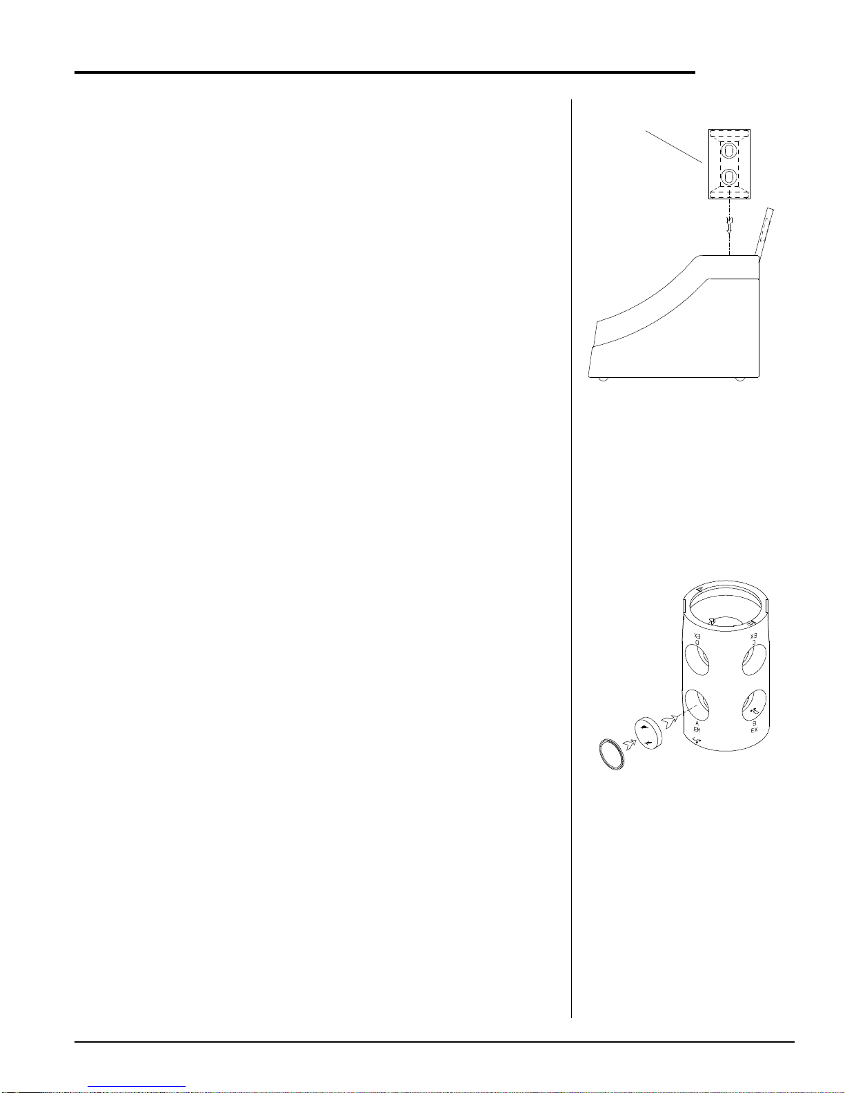
d. Findtheopeningsforthefilter setyouwanttoremove.Forexample, if
youwant to install thefilters in position B, thenremove any filters from
theB/EX andB/EMopenings. Toremovea filter,takeout theflexible
rubber o-ring holding the filter in place. Use a tool such as a plastic
pen cap or plastic-nosed forceps to do this. Be careful not to scratch
thesurfaceof the filter.Placeyourhandover theopeningandtiltthe
cylinder so the filter drops out into your hand.Be careful, the filters
are glass and may break if dropped.
e. Locatethe excitation filter to beinstalled.Handle the filter onthe
edgessoastoavoidleavingfingerprintsonthefilter,orwipeoffthe
filterbeforeinstalling.Ifthefilterhasonesidethatis“mirrored”or
highlyreflective,itshouldbeinstalled sothemirroredside faces
outwardfromthecylinder(towardthelamp).Insertit(mirroredside
out, if any) in the opening marked with the set letter/”EX”. Push the
filter in so it rests flush with the back of the opening. Then reinsert the
o-ring and press it in until it is flush against the filter.