Behncke UV matic A20 User manual

Installation and Operating Instructions
UV systems UV matic A 20 / A 25 / A 35 / A 48
Technical specifications subject to change without notice. Last updated 12/2016.
2
1.1.1.
UME GmbH
Alkersleber Weg 151 a
D-99334 KIRCHHEIM
Phone: + 49 036200 641 0
Fax: + 49 036200 641 20
E-Mail: [email protected]
Internet: www.umex-gmbh.de, www.abox-uv.de
Author: UME GmbH
Version: 01_2016
Datum: 07.01.2016
1.1.2.
ABO ® is a registered trademark of UME GmbH, with headquarters in Kirchheim,
Germany and protected as a trademark. (EU-Community trade mark EM 009 590 977,
ABO
®
).
All you provided information and technical data of the product are treated confidentially.
Publications may only with the consent of the manufacturer done.
Subject to technical modifications.
If you have any questions, please contact your partner, supplier or the manufacturer
directly (using the above contact details). The manufacturer can be contacted during
normal business hours, Monday to Friday.
To ensure prompt handling of your enquiry, please ensure you have your system’s serial
number (e.g. A-25-01112222) to hand. The number can be found in the following
places:
Identification plate
Delivery note
Invoice
Please read the User Manual carefully and keep it in a safe place!

3
1.1.3 Table of contents
1. Introduction
1.1.1. Communication
1.1.2. General information
1.1.3. Table of contents
1.1.4. Liability and warranty
1.1.5. General and residual risk
1.1.6. Information about this
User Manual
2. Safety
2.1.1. Explanation of symbols
2.1.2. UV light protection
2.1.3. Safety instructions
2.1.4. Hazardous situations and
safety instructions
2.1.5. Work on the electrical
subsystem
3. Intended use
3.1.1. Technical method
4. Product and ethod
ter inology
5. Technical specifications
5.1.1. Service life of main
modules/ancillary equipment
6. Design and confor ity
6.1.1. Interfaces
7. Syste description
7.1.1. UV reactor
7.1.2. Control box
7.1.3. Controller overview
7.1.4. Menu navigation
7.1.5. Switching output
7.1.6. Operation of the UV-device
8. Installation
8.1.1. Requirements for installation
at the customer
8.1.2. Reactor
8.1.3. Electrical sub system
9. Co issioning
9.1.1. Reactor
9.1.2. Switch cabinet and system
9.1.3. Power cable connection
9.1.4. Troubleshooting
10. Maintenance and service
10.1.1. General information
10.1.2. Changing the UV lamp
10.1.3. Inspecting the quartz
immersion tube
10.1.4. Cleaning the immersion tube
11. Cleaning the irradiation
cha ber
11.1.1. Cleaning with cleaning agents
12. Disposing of used e itters
13. Transportation and storage
14. Spare parts
14.1.1. List of spare parts
15. Operations log book
15.1.1. Notes
16. Declaration of Confor ity
17. Circuit diagra
4
1.1.4. Liability and warranty
For warranty claims, we are liable only to the extent permitted by the law or according
to the terms of the warranty given in agreements as concluded. Other matters are
governed by the General Terms & Conditions of your partners, suppliers or UME GmbH.
We draw your attention to the fact that the warranty is voided by damage resulting
from:
– Errors made during installation or operation
– Product usage not covered by intended use
– Modifications to the system
– Maintenance or service work not carried out to professional standards
– Removal or modification of safety mechanisms
– Failure to use original replacement parts/wear and tear
1.1.5 General and residual risk
The UV systems have been manufactured to the latest technical standards. Residual risk
in the form of material defects, mechanical breakage of the glass or other external
factors – can cause defects in individual modules. In such cases, please get in touch with
your contact person or a technical specialist. Always contact a technical specialist if
water has come into contact with the electrical modules.
1.1.6 Infor ation about this User Manual
The User Manual provides you with the basic information and guidance needed to
operate the UV system. Before starting any activity, please first read the corresponding
chapter(s) in this Manual. For your own safety, please always follow the safety
instructions that are given.
Operation of the UV system is also subject to the local accident prevention regulations
and general safety precautions applicable to its area of application.
Warning
This syste s works with UVC radiation!
UVC radiation can da age the skin and eyes!
Always wear protection when working with UVC!
5
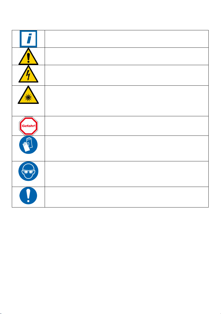
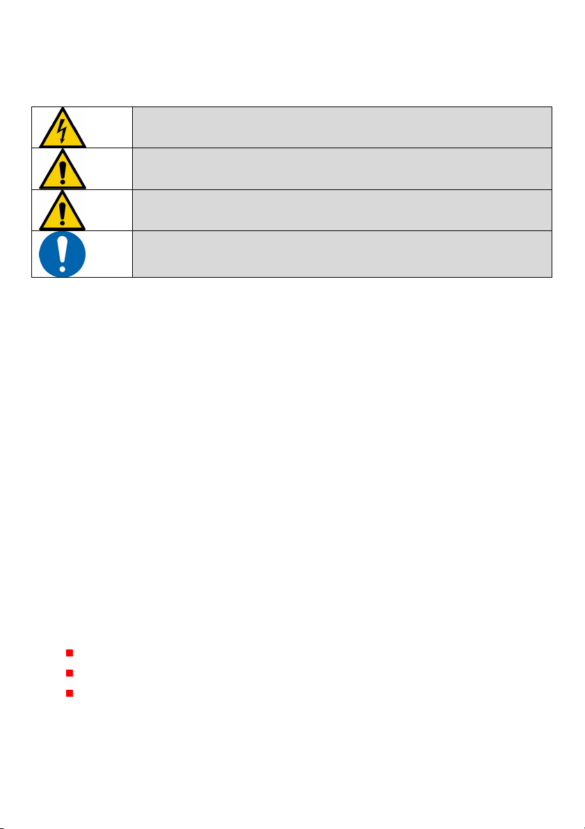
2.1.1 Explanation of sy bols
Notice
General information.
Warning
Important information or prohibitions to avoid causing damage.
Warning
Warns the user about dangerous electrical voltage.
This sign is used for activities involving system components carrying
live current.
Warning: UVC radiation
If your eyes are not protected, looking at UVC for only a few seconds
(and at a distance of several metres) is enough to cause a painful
inflammation, similar to the “arc eye” experienced when welding, noticed
only hours later. Irradiation of the skin for just a few minutes is enough
to cause serious sunburn.
Danger
Danger to health and life if the appropriate safety precautions are not
followed.
Mandatory
Wear appropriate clothing and gloves to protect the skin.
Gloves also avoid leaving traces of grease on glass parts.
Also offers protection against cleaning agents.
Cotton gloves can be supplied as accessories.
Mandatory
Safety goggles must be worn at all times to protect the eyes. Only pure
quartz glass is UV-C-permeable. Also offers protection against cleaning
agents.
Safety goggles can be supplied as accessories.
Mandatory
Danger of malfunctions/damage to the UV system if the appropriate
safety precautions are not followed.
2.1.2 UV light protection
During normal operation of the UV system, the UV emitters are completely enclosed and
no UV light can escape from the UV reactor. This means operating personnel cannot be
exposed to any danger from UV light.
When checking system functions, troubleshooting or performing maintenance and
servicing, it may be necessary for a live UV emitter to be less than fully enclosed. In
such cases, suitable protection for the skin and eyes – in particular – MUST be worn.
6
Safety
The installation, commissioning, operation and maintenance of the UV system must be
performed by trained and authorised personnel at all times. These appropriately qualified
personnel must have read and understood the relevant sections of this Manual, and the
safety-relevant sections in particular.
If in any doubt, please contact your specialist dealer or the head office of the
manufacturer UME GmbH. Full contact details are provided at the front of the
document.
Before opening or installing the system, ensure it is not connected to power or pressure
lines.
Before cleaning, maintenance or replacing machine parts, isolate the system from all
power sources.
Always follow the operating instructions and comply with the permissible technical
specifications that are appropriate for the specific application.
Always observe occupational safety and accident prevention regulations, and comply
with any other generally recognised health and safety at work standards.
Before commissioning the UV system, ensure that all of the safety-related requirements
have been fulfilled and that safety mechanisms are in working order.
The UV system must only be used under the operating conditions for which the system
has been specifically designed (flow rate, SAC, etc.).
The UV system must be taken offline immediately if components are damaged or are not
in proper working order. All structural or technical modifications to the UV system are
PROHIBITED.
2.1.3 Safety instructions
Potential risks for personnel and/or the UV system itself are listed, assigned to the
respective sections in this Manual and marked with these symbols.
See - “Explanation of symbols”.
Risks are assigned to one of two categories:
UV-related risks = hazard arising fro UVC radiation
Danger to health and life if the appropriate safety precautions are not
followed.
Non-UV-related risks = hazard arising fro work with electrical power or other
achine handling risks
Danger of malfunctions/damage to the UV system if the appropriate
safety precautions are not followed.

7
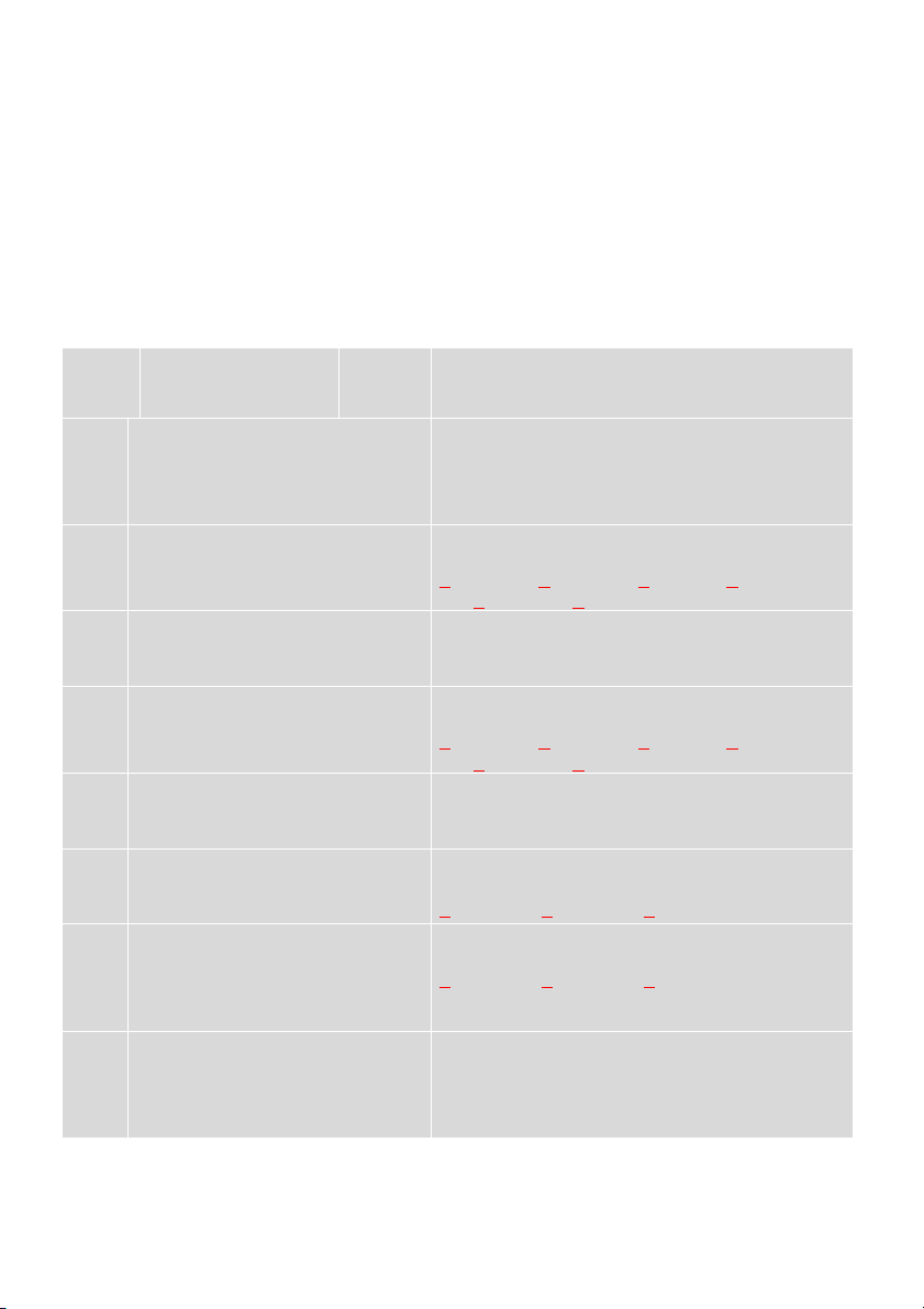
2.1.4 Hazardous situations and safety instructions
Situation Subsyste Hazard Action to take
Installation/removal
of UV emitter or
immersion tube
UV reactor Burn injury
UV emitters become
very hot during use.
Laceration injury
UV emitters and
immersion tubes are
fragile
(quartz glass).
Take the UV system
offline and secure the
master switch to prevent
accidental switch-on.
Depressurise and empty
the UV reactor
Functional checks
UV emitter
UV reactor UV light causes
damage to eyes and
skin
Never switch on the UV
emitter outside the UV
reactor.
Emptying the reactor UV reactor Reactor is
pressurised.
Wear personal protective
equipment (PPE).
Open the vent valve
slowly (pressure relief
valve).
Cleaning the reactor UV reactor Chemical burn
Cleaning agents
contain acids.
Take the UV system
offline and secure the
master switch to prevent
accidental switch-on.
Wear personal protective
equipment, take
appropriate precautions
concerning the handling
of acidic liquids, follow
manufacturer
instructions about the
use of cleaning agents.
Do not eat or smoke
while working.
Replacing emitters,
work on electrical
subsystem
UV system Electrical shock.
Disconnect from the
power supply and isolate
from customer input
signals as required.
Secure the UV system to
prevent accidental
switch-on.
Electrical work must be
carried out by
professionals.
8
2.1.5 Work on the electrical subsyste
For all work on the machine’s electrical subsystem, the following safety precautions
MUST be observed/followed at all times:
Warning! The voltage used to operate the machine can be dangerous
device
The system must only be opened by trained technical specialists
Isolate the machine before opening the switch box
Read the User Manual before opening the machine
3. Intended use
The ABO
®
ultraviolet systems deactivate microorganisms, like germs, viruses and
yeasts in the water. The system works efficiently only if clear free from iron and
manganese water is supplied. The function is guaranteed only within the limits of the
technical data of the device. ABO
®
UV-system UV-irradiation devices can be installed
directly into the water supply pipe. The System should be installed in the supply directly
before any ancillary distribution pipe work and possible storage reservoirs
3.1.1. Technical ethod
UV-disinfection is a process that takes place when water flows through the reactor
chamber. Microorganisms are exposed to UVC-irradiation and will be deactivated within a
few seconds. This means the cells photochemical reactions are released which inhibit
further cell division and render the microorganisms harmless.
The advantages of the procedure are
No addition of chemicals
No formation of harmful by products
Deactivation of microorganisms takes place for a few seconds

9
4. Product and ethod ter inology
Ter Explanation
UV system The UV system is the complete system, consisting of the UV
reactor, the switch cabinet and the ancillary equipment.
UV reactor Core component in a UV system, consisting of a reactor housing
plus reactor chamber, UV emitters, immersion tubes and UV
sensors with various screw fittings.
Switch cabinet Core component in a UV system, consisting of a switch cabinet
housing with ballast units to supply the UV emitters with power,
an analysis unit for the UV sensor and electrical components to
operate the UV system.
UV emitter Component in the UV reactor that generates UV light. The UV
emitter is integrated into the immersion tube.
Immersion tube Component in the UV reactor that is immersed in water. The
immersion tube contains the UV emitters.
UV sensor Component for the continuous measurement of the UV-C
irradiation strength in the irradiation chamber.
Deposit Deposition of waterborne substances in the irradiation chamber,
and esp. on measurement window and immersion tube.
Shutoff valve Used to shut off the flow of water in inlet/outlet, manually or
automatically.
Irradiation chamber Part of the UV reactor where water flows through.
Disinfection Killing off/inactivation of microorganisms, including pathogenic
microbes.
Minimum irradiation
strength
A value for measuring irradiation strength, specific to the type of
UV disinfection device and application, measured with a UV
sensor. The minimum irradiation strength and maximum flow
rate must be maintained during operation of UV disinfection
equipment to ensure the required level of disinfection is
achieved.
UV dose (fluence) Specified in J/m
2
or mJ/cm
2
. The amount of UV light that must
be applied in order to achieve a specified disinfection result. A
metric for disinfection capability.
UV transmission Relationship of emitted irradiation to incident irradiation. UV
transmission is measured in % on a layer thickness or specified
as a spectral absorption coefficient of the wavelength 254 nm
(SAC-254).
The SAC measurement encompasses both absorbent water
constituents (colour) as well as the scattering of light by
suspended particles (turbidity).
W/m² Unit of measure for UV irradiation strength.
UV-C Shortwave (200–280 nm) UV light, a part of the electromagnetic
spectrum.
UV light Light invisible to the human eye, generated by the sun or a UV
emitter.
Boot phase Time from when the UV system is switched on to “System ready
for use”.
Minimum flow rate Required to avoid overheating.
Emitter lifespan Expected usable lifespan followed by degradation of UVC 254 nm
output
HG lamps UV-C mercury lamp
HGA lamps UV-C doped mercury amalgam lamp

10
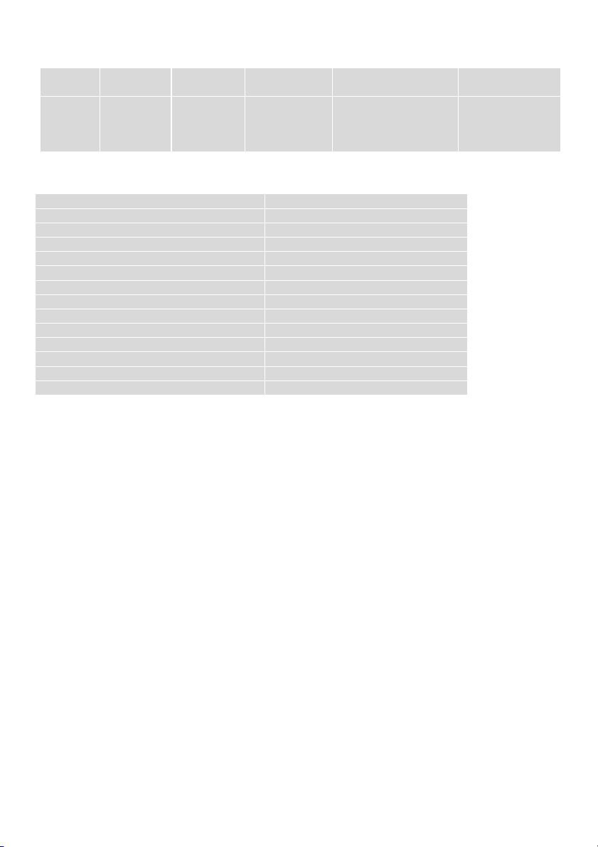
5. Technical data
Manufacturer : UME GmbH, D-Kirchheim, www.umex-gmbh.de
Type : UV-matic A, exclusive mark for BEHNCKE
Reactor : Stainless steel, 1.4571 (316)
bath-pickled and electric-polished
Life time of lamps : 8.000 h in continuous operation
Water temperature : UV-matic A 20 and A 25 = 1 - 35 °C
UV-matic A 35 and A 48 = 2 - 55 °C
Water characteristics : no corrosive qualities, chloride level <500 mg/l,
with max. 38°C and without air entry
Ambient temperature : 2-35 ° C with maximum air humidity
of 70% at 35 ° C
Working pressure max. : 10 bar
Bezeichnung UV- atic
20
UV- atic
25
UV- atic
35
UV- atic
48
Floe rate 10 m
3
/h 15 m
3
/h 25 m
3
/h 40 m
3
/h
Capacity basin 50 m
3
75 m
3
125 m
3
200 m
3
Rate reaktor 1.000 mm 1.000 mm 1.000 mm 1.300 mm
Weight reaktor ca. 8 kg 8,5 kg 11 kg 12,5 kg
Pipe connection 1 ½“ 2“ 2“ 3“
Reaktor Ø 114 mm 114 mm 139 mm 168 mm
Length of uv lamp 880 mm 845 mm 860 mm 1.120 mm
UV- electrical power 60 W 80 W 120 W 200 W
UV-C- power 25 W 27 W 35 W 60 W
UV-unit size 185 x 205 x 80 mm HxWxD
Mains electricity
supply
230 V AC ± 10%
Artikel- Nr.: 129 200 129 250 129 350 129 480
*Arithmetic Qmax, hydraulically limited at 250 J/m
2
** In Germany, section 411.4.5 of the DIN VDE 0100-410:2007-06 standard expressly
prohibits the use of residual current devices in TN-C systems (earthing system).

11
5.1.1. Life of the ain odules / resources
Equip ent
aintenance
Intervals Testing and inspection Max. Life life
UV lamp T 8,000 h 8,000 -10 000h
Quartz immersion tube R, T 8,000 h 48 months *
Gasket Set P, T 8,000 h 12 months
UV sensor P, T P, T 48 months
Electronic Ballast(EVG) P, T 8,000 h 48 months *
Fuses P, T with Maintenance 48 months *
UV reactor R, K, T with Maintenance 120 months *
Switchbox K, P, T with Maintenance 120 months *
Stainless steel modules R, K with maintenance 120 months *
Screw connection K, T with Maintenance 24 months *
R = cleaning
T = exchange
K = control
P = Check
* Reusing after examination
Grey marked = wearing parts
6. Design and in confor ity to
Low-voltage switchgear unit combination
IEC 61439-1/-2 2011 EN 61439-1/-2 2011 VDE 0660-600 2012
Low Voltage Directive 2014/35/EU EMC Directive 2014/30/EU
DIN EN 60335-1:2005-07 safety of electrical installations both in household,
commercial, industrial and water sectors
6.1.1. Interfaces
Switch box / cabinet
terminal strip
fuse
Reactor flange UV system
Installation site
Indoor frost-free
Maximum humidity 70% at 35 ° C
Ambient temperature max. 35 ° C
water temperature
35° C HG lamps
55° C HGA lamps
Special operating conditions
Accessible to operation and maintenance
Compliance with the line length

12
7. Syste description
The UV system consists essentially of a UV reactor and the corresponding switch cabinet.
The UV system is delivered ready for installation. Connection cables for the UV emitter
and UV sensor are included in delivery.
7.1.1. UV reactor
Protective cap
Screw joist
leed valve
Outlet
UV-sensor
Quartz sleevers liner
UV-lamp
Reaktor
Drain
A
C
Lamp exchang
D
Inlet
PE
Type UV-matic A
20
UV-matic A
25
UV-matic A
35
UV-matic A
48
A 1.000 1.000 1.000 1.300
B 835 820 820 1.075
C 195 200 220 270
D 900 900 900 1.200
Reactor/stan Ø 114/175 114/175 139/200 168/230
Pipe connection 1 ½“ 2“ 2“ 3“
13
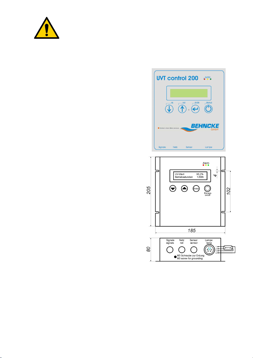
7.1.2. Switchbox the series UV atic
The UV system switch cabinets are designed for automated operation.
All UV systems have been given a 100% factory test prior to shipping. The switch boxes,
modules and terminal blocks have been tested against the applicable standards.
Complete control unit with integrated
electronic ballast, UV monitor and hour
counter in an own housing. The unit is wired
ready for connection including the sensor.
It can be combined with 4 different lamps
between 60 to 200W.
Safety check of the coded UV lamp cable
when each switching on.
Description
•for 230±10% VAC main voltage supply
•integrated electronic ballast for 60W, 80W,
120W, 200W
•safety circuitry prevent damages in case of
ground fault, short circuit, end of lifetime
and overtemperature
•control via menu in German, English,
Russian
•two line alphanumeric display is
background illuminated allows displaying
UV value and lamp working hours at the
same time
•4 switching outputs available, threshold
values programmable
•daylight blind UV-sensor SUV13.1 A1 C
optional
•calibration of the UV value via menu
possible
counter for global and lamp hours, lamp hour
resettable
14
7.1.3. Controller overview
power net
current
sensor enu
language
la p / current accessory
cable
60-200
W
max.
1,0 A*
SiC-sensor
SUV13.1A
German
English
Russian
HG 60/4 / 0,67 A
HG 80/4 / 0,80 A
HGA 120/4 / 1,5 A
HGA 200/4 / 2,0 A
type 1 - 60W
type 2 - 80W
type 3 - 120W
type 4 - 200W
Controller technical data:
Mains electricity supply 230 V AC ± 10%
Mains frequency 50 - 60 Hz
Operating frequency 25 - 65 kHz
Efficiency > 90%
Cos φ 0.96
Pre heating Yes
A bient te peratur 0 - 45°C
Case te perature 50°C ax.
Fault warning relays 24 VDC/230 VAC, 50 A-5A
Installation vertikal
Size (H x W x D) 205 x 185 x 80
Cable length net, la p, sensor 2.5
Degree of protection IP 65
Gewicht 2000 g
UV onitor
The relative UV-intensity is read by a sensor and shown in the display. When dropping
below the minimum alert value (e.g. 50%) „Pre-alarm“ is signalled by a yellow LED and
appropriate relay contact. When the lamp fails “Main-alarm” is signalled by the red LED
and the appropriate relay contact.
Hour counter
Total hours and lamp hours are counted continuously. The internal value will renewed
every hour. The lamp hours are shown on the display and can be reset when the lamp
will be changed.
Menu
You reach the menu by pressing the Enter button 2 seconds. With buttons / you can
browse through the menus up / down. Enter calls up the menu point for changes. Either
the changing will occur immediately or the value will called and can be changed
afterwards. With buttons / you can modify the values. With Enter the adjusted value
will be acknowledged / stored. After 10 seconds waiting an automatically return to the
basic display will take place.
15
7.1.4. Menu navigation
With the first installation all menu options are served and adjusted.
Everyone turns out before the distribution is examined and adjusted as follows.
Standard setting:
1 = Language German 5 = Half
2 = 1 6 = 50%
3 = 0 7 = 110%
4 = 8.000 8 = Drinking water
enu
-
entry
display shows line 1
line 2 action with pressing ENTER
1 language
English
every ENTER will choose the next language
German English Russian German
...
The chosen language will appear on the
display immediately
2 la p hours
<nu ber of la p hours>
ENTER displace the cursor one digit, / for
value adjustment
00000 00000 00000 00000
00000 00000 back
3 overall hours
<nu ber of overall hours>
only display
example: 008023 h back
4 la p life ti e
<la p life ti e in hours>
ENTER displace the cursor one digit, / for
value adjustment
00000 00000 00000 00000
00000 00000 back
5
display contrast
<bar for contrast
adjust ent>
ENTER calls the bar, / adjustment less /
more
6
UV warning
<alar threshold value
in %>
ENTER displace the cursor one digit, / for
value adjustment
000 % 000 % 000 % back
7 calibration value
<end value in %>
ENTER displace the cursor one digit, / for
value adjustment
000 % 000 % 000 % back
Attention: maximal adjustable value is
110 %!
8 calibration
<current value in %>
ENTER an alignment to the value above will
occur
Attention: lamp must be at it working
temperature! You can check that if the value
will not change after alignment.

16
7.1.5. Switching output
The switchbox is IP 65 conformal. Around degree of protection to ensuring, a lacquer
protection is appropriate at the lower screw of the back. Attaching the reporting exits
may take place only from an experienced specialist around the operability and ensure
the tightness of the switchbox.
The accompanying picture shows the
way of the wiring which can be kept.
In the lower picture and in the table
the allocation of the relays is shown.
Opinion from the rear, cable supply right.
Fault warning relays 24 VDC/250 VAC, 50mA-5A
Configuration of the relays
Relai
s
LED Infor ation
Rel. 1 green Correct opration
Rel. 2 yello
w
Alarm theshold
overtravel
Rel. 3 red UV lamp failure
Relay configuration cut out
17
7.1.6. Operation of the UV-device
The UV systems uv matic 25 is for water temperatures 2-35 °C and the UV systems uv
matic 35 maximum 55 °C designed for continuous operation.
In addition, a continuous water flow at the specified rate is required for optimal
operation.
Please see the data sheet for your specific model.
During fluctuating operating times, please monitor the reactor temperature to avoid
damage to the equipment and associated pipe work.
The efficiency of the UV-device is determined by the UV-intensity in the reactor. This
decreases during operation by lamp ageing or deposits on the inner quartz tube. This
also applies to unstable UV-transmission turbidity values, air temperatures or lower
throughputs.
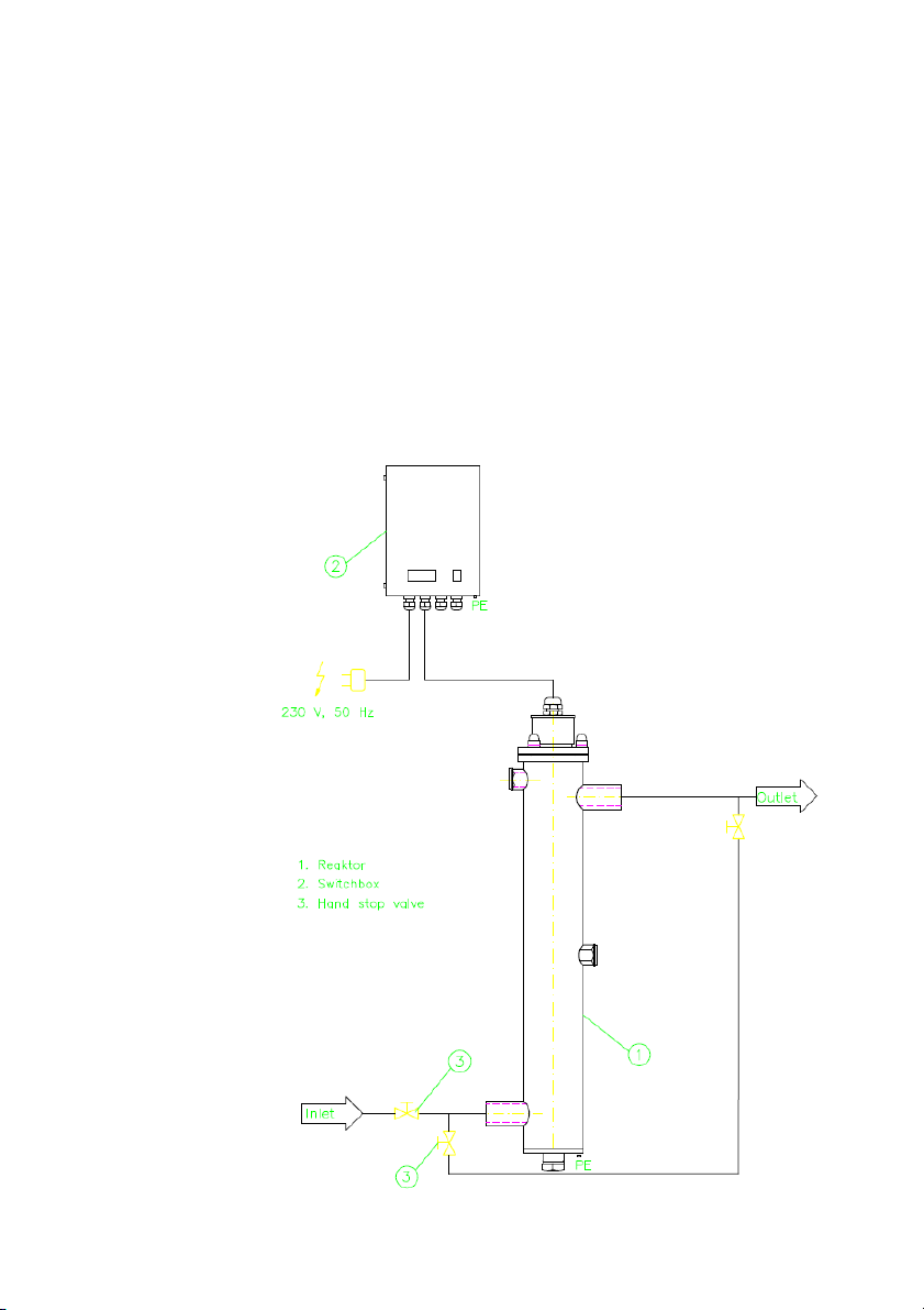
Exa ple installation sche e

18
8. Installation
The installation and commissioning of the System should only be undertaken by trained
specialists. Handling glass and UV-RADIATION requires special care. If you are in doubt,
please contact us. All contact details are on the first page.
The opening and installation of the device is only permitted when there is no water
pressure and no connection to electrical power. Before cleaning, maintenance or the
exchange of parts the system should be safely isolated from the electricity supply.
1. When installing, please consider free space for lamp change and general
maintenance.
See System description 7.
2. Protect against direct solar irradiation and against frost.
For general installation of the UV equipment, please see drawing, 7. For horizontal
installation must be ensured the ventilation in the UV reactor. In addition, the UV sensor
should not stand up, only horizontally or downwards to be installed in the water ring.
3. Installation of the UV-device should be completed with appropriate rubber lined
clamps or other suitable means (PVC-type).
4. Earthing/Grounding of the reactor and Switch Cabinet should be completed
according to local Regulations.
5. Fastening connections to the input/output (and to sampling valve).
6. Test for hydraulic pressure integrity in the reactor water. (Outlet key in the
accessories).
7. Install the switch cabinet in a suitable place. Please consider Cable lengths for
plug and la p cable.
8. Attach the lamp connector to the socket. Caution this can only be connected in
one orientation. Do not force the connection. Please ensure a good, snug fit.
9. The sensor and measuring window are screwed into the sensor connection in the
middle of the reactor. When installing the sensor screw connection, please note the
groove and notch arrangement. When the screw connection is secured, the installation
conforms to IP 65.
10. Optional! Cable connection for safety devices produce! For this purpose
11. Either ‘hard wire’ or use a plug and socket to connect to the mains depending on
your local regulations.

19
8.1.1. Require ents for installing the UV syste at the custo er
8.1.2. Reactor
Action to take Purpose
Installation indoors
Frost-free operation, protection against
direct solar radiation
Avoids damage to the system
Inspection of installation for
machine/method integration
System check
Check the working pressure, ambient
temperature and supply voltage
Protects the UV system
Ensure that sufficient clearance is available
in accordance with the installation
dimensions
Maintenance and service work
Ensure that pressure surges are avoided
– Charging and venting the reactor
– Slow ramping up of the pump (frequency
converter)
– Slow opening of the valves
(valve control system)
- Vented supply lines
Avoids damage to the UV reactor
Ensure that the reactor mounts (external to
the machine) are designed to support the
corresponding weight.
Ensures safe installation and protects the
system
Keep an eye on rinse processes and install
an external inlet/outlet system with
solenoid valves if required.
Keep Qmax n mind in this context.
Protects the UV system from overheating
Automatic operation of the system
Ensure that appropriate precautionary
measures are taken during installation so
as to prevent the distribution of untreated
water.
Ensures process safety
8.1.3. Electrical subsyste
Action to take Purpose
Ensure the supply of the necessary
operating voltage
Avoids malfunctions
Damage to the system
Check current-limiting fuses and protective
mechanisms (RCDs)
Avoids malfunctions
Ensures safe installation and protects the
system
Inspect the location chosen for wall
mounting. Double-check cable lengths.
Avoids malfunctions
Ensure that ambient temperatures do not
exceed 35 °C and the location is suitable
for a protection class of IP 54
Avoids overheating
Ensure professional installation of
connection cables and signal loads
Avoids malfunctions

20
9. Introduction
Warning
Important information or prohibitions to avoid causing damage.
Warning
Warns the user about dangerous electrical voltage.
This sign is used for activities involving system components carrying live
current.
Warning: UVC radiation
If your eyes are not protected, looking at UVC for only a few
seconds (and at a distance of several metres) is enough to cause a
painful inflammation, similar to the “arc eye” experienced when
welding, noticed only hours later. Irradiation of the skin for just a
few minutes is enough to cause serious sunburn.
Danger
Danger to health and life if the appropriate safety precautions are
not followed.
9.1.1. Reactor
Requirements
Water pipes are ready for the installation.
The correct water pressure is available.
Electrical connections are ready to be energised at the switch.
9.1.2. Cabinet and syste
Switchgear cabinet is mounted and electrical connections ready.
UV lamp is correctly installed.
ONLY OPERATE THE UNIT WITH THE CORRECT UV LAMP.
9.1.3.
Power cable connector
The system is switched on via the On / Off switch.
This manual suits for next models
3
Table of contents
Popular Laboratory Equipment manuals by other brands


Omega Engineering
Omega Engineering TJ-USB user guide

W&H
W&H Lisa VA131-17 Instructions for use

Wavelength Electronics
Wavelength Electronics QCL500 LAB user guide

89 North
89 North PhotoFluor II operating manual

Thermo Scientific
Thermo Scientific Gibco CTS Rotea user guide

Helmer Scientific
Helmer Scientific i.Series Pro Series Service manual