Turner Turbidity Plus User manual

User’s Manual
February 28, 2020
P/N 998-2187
Revision G
TURNER DESIGNS
1995 N. 1st Street
San Jose, CA 95112
Phone: (408) 749-0994
FAX: (408) 749-0998

Turbidity Plus Sensor
998-2187 Rev. G Page 2
Table of Contents
1.
Introduction
1.1
Description
4
2.
Inspection and Setup
2.1
Housing Configurations
5
2.2
Optional Accessories
5
2.3
Functional Test for Turbidity Plus with connector with P/N 2200-170
7
2.4
Functional test for Turbidity Plus with connector with Fondriest
Cable
2.5
Functional test of the wiper for the Turbidity Plus with connector
P/N 2200-170
8
2.6
Functional test of the wiper for the Turbidity Plus with connector
with Fondriest Cable
9
3.
Calibration
3.1
Direct Concentration Calibration for Turbidity Plus
10
4.
Integration
4.1
To take measurements
12
4.2
To trigger wiper
12
5.
Maintenance and Warranty
5.1
Maintenance
14
5.1.1
Rinsing
14
5.1.2
Care for the bulkhead connector
14
5.1.3
Cleaning the Optics
14
5.2
Warranty Terms
14
5.3
Warranty Service
14
5.4
Out of Warranty Service
15
Appendices
A
Specifications
17
B
Recommended Measurement Practices
18
C
Pigtail Cable and Connector Information
19
D
Functional Test for Turbidity Plus with no Connector
20

Turbidity Plus Sensor
998-2187 Rev. G Page 3
WASTE ELECTRICAL AND ELECTRONIC EQUIPMENT (WEEE)
DIRECTIVE
Turner Designs is in the business of designing and selling products that benefit the
well-being of our environment. Accordingly, we are concerned with preserving the
surroundings wherever our instruments are used and happy to work with customers
by complying with the WEEE Directive to reduce the environmental impact resulting
from the use of our products.
WEEE Return Process:
To arrange the return of an end-of-life product, proceed as follows:
If you purchased your instrument through a Turner Designs Distributor please
contact your local representative. They will instruct you where to return the end-
of-life product.
If you purchased your instrument directly from Turner Designs please contact
Turner Designs Customer Service
By Phone: 1-408-212-4041 or Toll Free: (877) 316.8049
By Email: Customer Service at support@turnerdesigns.com
Turner Designs will provide a WEEE RMA Number, a Shipping Account
Number, and a Ship to Address. Package and ship the product back to Turner
Designs.
The product will be dealt with per Turner Designs’ end-of-life recycling program in
an environmentally friendly way.

Turbidity Plus Sensor
998-2187 Rev. G Page 4
1. Introduction
1.1 Description
Turbidity PlusTM is an accurate single-channel turbidity sensor with an
integrated, user-controlled wiper motor. It is designed for integration with
multiparameter systems and dataloggers from which it receives power and wiper
motor triggers at user-defined intervals. Turbidity Plus is available in two linear
ranges up to 500 or 3,000 NTU with minimum detection limits of 0.05 or 0.5 NTU
respectively. It delivers a voltage response proportional to the turbidity of the
sample which can be correlated to nephelometric turbidity unit (NTU)
concentrations by calibrating the sensor using AMCO Clear Turbidity Standards.
Deployable to 200 meters, Turbidity Plus is available in a variety of
configurations to facilitate integration.

Turbidity Plus Sensor
998-2187 Rev. G Page 5
2. Inspection and Setup
2.1 The Turbidity Plus Sensor is available in the following configurations:
Turbidity Plus Sensor with Integrated Wiper P/N 2180-000
oFully configured with connector and complete wiper assembly
Turbidity Plus with Integrated Wiper Motor and Wiper Assembly, No
Connector P/N: 2180-000-NC.
Turbidity Plus with Integrated Wiper Motor, No Wiper Assembly, No
Connector P/N: 2180-000-NCW
Turbidity Plus with Integrated Wiper Motor and Wiper Assembly, No Housing
P/N: 2180-000-NH
Turbidity Plus with Integrated Wiper Motor, No Wiper Assembly, No Housing,
P/N: 2180-000-NHW
500 NTU Turbidity Plus with Integrated Wiper P/N 2185-000
oFully configured with connector and complete wiper assembly
Note: The wiper shaft has a flat edge for the application of a set screw to
avoid unwanted movement of the wiper assembly.
2.2 Optional Accessories:
0.6 meter Pigtail Cable with Locking Sleeve P/N 2200-170
Turner Designs does not sell cables longer than 0.6M for the Turbidity
Plus. We recommend the following Fondriest Environmental products.
Fondriest Environmental
2091 Exchange Court
Fairborn, OH 45324
888.426.2151
937.426.2151
https://www.fondriest.com/nexsens-mcil-female-cable-assemblies.htm
P/N MCIL-8-FS-5 5 meter Pigtail Cable with Locking Sleeve
P/N MCIL-8-FS-10 10 meter Pigtail Cable with Locking Sleeve
Note: Fondriest cables have an orange outer shielding, consult wiring
instructions Figure 2 for pinout.

Turbidity Plus Sensor
998-2187 Rev. G Page 6
Note: Turbidity Plus without connector refer to Appendix D.
2.3 Functional test for Turbidity Plus with connector with Pigtail P/N 2200-170.
To perform a functional check on Turbidity Plus, connect the Pigtail
P/N 2200-170 colored wires to the power supply and multi-meter as shown in
Figure 1 below.
Additional Equipment required for functional tests:
DC Power Supply: 3-15 VDC, >100 mA
Multi-meter to read: 0 –5 VDC
Note: Supply voltages greater than 9 VDC will result in damage to the
sensor.
Figure 1
2
6
4
7
1
5
3
28
5
Turbidity Plus pins Pigtail P/N 2200-170
2
4
6
3
1
5
7
82
5

Turbidity Plus Sensor
998-2187 Rev. G Page 7
2.4 Functional test for Turbidity Plus with connector with Fondriest Cable P/N
MCIL-8-FS-5/10 5 or 10 meter Pigtail Cable with Locking Sleeve.
To perform a functional check on Turbidity Plus, connect the Fondriest Cable
colored wires to the power supply and multi-meter as shown in Figure 2 below.
Additional Equipment required for functional tests:
DC Power Supply: 3-15 VDC, >100 mA
Multi-meter to read: 0 –5 VDC
Note: Supply voltages greater than 9 VDC will result in damage to the
sensor.
Figure 2.
12.00 .015
+ -
DC Power Supply
PSU Positive Connection
Red (3)
Supply Ground
0 VDC Brown (4)
3.52
Multimeter
10 VDC
+-
Signal Output
“+” Yellow (5)
Analog Ground
“-” White (6)
Orange (1) Black (2)
No Connection
Turbidity Plus Pigtail Cable
Home Signal
Blue (7)
Wiper Trigger
Green (8)
Orange Cable
Wire Color Pin Function
Orange 1 N/A
Black 2 N/A
Red 3 Supply Voltage 3-15 VDC
Brown 4 Supply Ground 0 VDC
Yellow 5 Signal Out “+”, 0-5 VDC
White 6 Signal Ground “-”, 0-5 VDC
Blue 7 Home Signal
Green 8 Wiper Trigger. 3.2 VDC
Turbidity Plus pins
2
4
6
3
1
5
7
82
5
2
6
4
7
1
5
3
28
5
Orange
cable holes

Turbidity Plus Sensor
998-2187 Rev. G Page 8
With Turbidity Plus connected as shown in Figure 1 and 2 perform functional
tests to answer the following questions:
1. Is there voltage output?
The multi-meter should be reading some voltage >0 VDC
2. Does the voltage output change?
Move the palm of your hand towards the optical head and check if the
voltage output increases
Note: A visual test of the LED for Turbidity Plus is not possible because it is
IR, which is not visible.
2.5 Functional test of the wiper for Turbidity Plus with connector with P/N 2200-
170.
To perform a functional check on the wiper, connect the Pigtail colored wires to
the power supply and multi-meter following the steps below, shown in Figure 3.
1. Disconnect the blue wire from the meter and connect the yellow wire in its
place. It should read about 0 volts.
2. Briefly touch the orange wire to the power supply ground.
3. The wiper should start rotating and the meter should read about 3.2 volts
until the wiper returns to its home position.
Figure 3.
Note: The sensor has built in protection if the wiper becomes blocked and
cannot move. In this case the wipe will stop and will try to return to the home
position the next time it is triggered.
Warning: Do not move the wiper by hand. This can cause permanent damage
to the sensor.
12.00 .015
+ -
DC Power Supply
PSU PositiveConnection
(Red)
Supply Ground
0 VDC (Green)
3.20
Multimeter
10 VDC
+-
Home Signal
(Yellow)
Analog Ground
“-” (Brown)
Black White
No Connection
Turbidity Plus Pigtail Cable
Output Signal
“+” (Blue)
Wiper Trigger
(Orange)

Turbidity Plus Sensor
998-2187 Rev. G Page 9
2.6 Functional test of the wiper for Turbidity Plus with connector Fondriest
Cable.
To perform a functional check on the wiper, connect the Pigtail colored wires to
the power supply and multi-meter following the steps below, shown in Figure 4.
4. Disconnect the yellow wire from the meter and connect the blue wire in its
place. It should read about 0 volts.
5. Briefly touch the green wire to the power supply ground.
6. The wiper should start rotating and the meter should read about 3.2 volts
until the wiper returns to its home position.
Figure 4.
Note: The sensor has built in protection if the wiper becomes blocked and
cannot move. In this case the wipe will stop and will try to return to the home
position the next time it is triggered.
Warning: Do not move the wiper by hand. This can cause permanent damage
to the sensor.
12.00 .015
+ -
DC Power Supply
PSU Positive Connection
Red (3)
Supply Ground
0 VDC Brown (4)
3.20
Multimeter
10 VDC
+-
Home Signal
Blue (5)
Analog Ground
“-” White (6)
Orange (1) Black (2)
No Connection
Turbidity Plus Pigtail Cable
Output Signal
“+” Yellow (5)
Wiper Trigger
Green (8)

Turbidity Plus Sensor
998-2187 Rev. G Page 10
3. Calibration
Note: To make accurate and repeatable measurements it is important to
keep the sensor clean; see Section 5.1 for information on cleaning your
sensor.Refer to Appendix B - Recommended Measurement Practices.
3.1 Direct Concentration Calibration
Calibrating Turbidity Plus is a simple process that requires calibration standards
to create a correlation factor which is used to convert raw voltage data to NTU
concentrations.
Turner Designs recommends Amco Clear Turbidity Standards. They are non-
toxic safe solutions consisting mainly of deionized water that come prepared in a
broad range of concentrations and have a shelf life guaranteed for one year.
These standards are available from GFS Chemicals under part numbers 8506
(10 NTU), 8507 (100 NTU), 8620 (1000 NTU) and 8621 (3000 NTU). Follow
instructions below to establish a correlation between the standard’s
concentration and the sensor’s voltage response. Use the equation in step 6 to
calculate NTU concentrations.
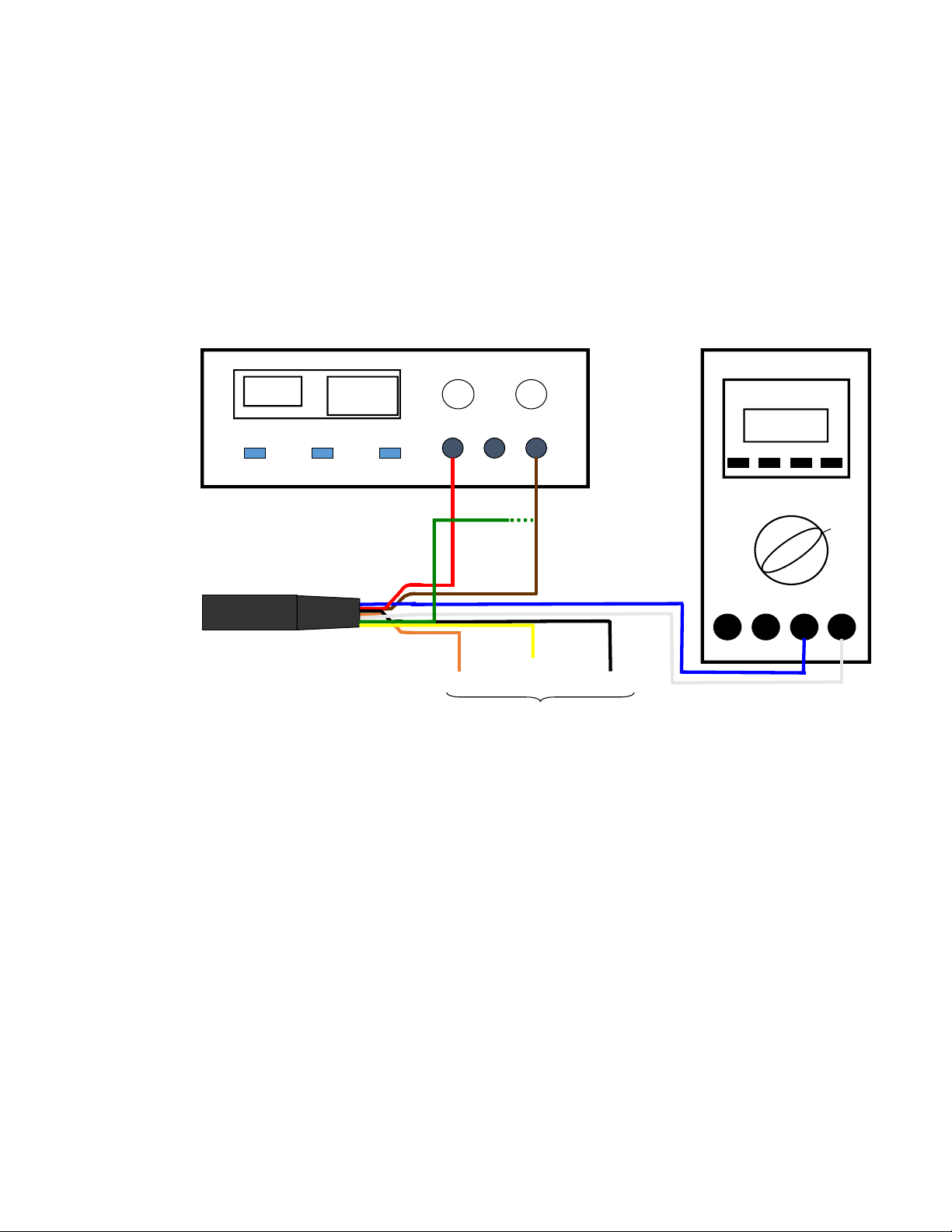
1) Connect Turbidity Plus to a power source and multimeter; see figure 1 for
details.
2) Fill a darkened beaker with blank sample and use Turbidity Plus to measure
the voltage of the blank.
Note: A good blank to use for this application is ultra-pure or
deionized water.
3) Remove Turbidity Plus from the blank, pour out the blank sample, and fill the
same darkened beaker with a standard solution of known concentration.
4) Measure the voltage response of the standard solution.
5) Use the following equation to create a correlation factor:
[(CStd)/(VoltsStd - VoltsBlank)] = Correlation Factor
CStd = Concentration value of standard used for calibration
VoltsStd = Voltage reading from standard concentration
VoltsBlank = Voltage reading from blank
6) Use the following equation to calculate concentration from measured voltage
response:
CSample = (Correlation Factor) * (VoltsSample –VoltsBlank)
Csample = Concentration of sample

Turbidity Plus Sensor
998-2187 Rev. G Page 11
VoltsStd = Voltage reading from standard concentration
Note: Calibration of Turbidity Plus is not required, but recommended.
Note: There is no Temperature Compensation built into Turbidity Plus.
The average percentage change of blank adjusted voltage is -0.45%
mv/degree
C of signal.

Turbidity Plus Sensor
998-2187 Rev. G Page 12
4. Integration
Once Turbidity Plus has been tested and/or calibrated you can proceed with
integration into your platform. Refer to the power requirements in Attachment A to
make sure that your system is set up correctly. Refer below for typical use with a
data acquisition system wiring configuration using P/N 2200-170 Figure 5 and
Fondriest Cable Figure 6.
Note: The wire colors are different for no housing or no connector versions,
refer to Appendix D for the colors.
4.1 Taking measurements:
1. Supply power to the sensor.
2. The digital output to the wiper trigger should normally be a “1” or high and
the digital input from the Home Signal should read “0” or low.
3. Take readings if desired, readings are valid 3 seconds after full power is
applied.
4.2 To wipe:
1. Take the digital output to the wiper trigger momentarily low or “0”. The wiper
will start rotating on the transition from high to low. Multiple rotations of the
wiper can be achieved by sending multiple pulses on the trigger wire while
the wiper is rotating, but after each triggered rotation there must be a 50
millisecond delay before the next triggered rotation. The wiper will rotate the
number of pulses it receives.
2. The home signal can be monitored on the digital input. It is normally a “0” or
low. When the wiper is rotating this signal will go to a “1” or high.
3. While the wiper is rotating (when the home signal is “1”) readings are not
valid.
4. When the digital input monitoring the home signal returns to “0” that means
the wiper is in the home position and readings are now valid.
Figure 5 –P/N 2200-170
* Black and White wires from the cable are not connected.
P/N
2200-170* Turbidity Plus Acquisition System
Red Supply Voltage Power Positive
Green Supply Ground Power Ground
Brown Signal Ground Analog Input Ground
Blue Signal Out Analog Input Signal
Orange Wiper Trigger Digital Output
Yellow Home Signal Digital Input
+-
PSU
Positive
3-15 VDC
PSU
Ground
0 VDC
Analog
Signal
+
Analog
Ground
-
Turbidity Plus Pigtail Cable
P/N 2200-170
Digital
Input
Digital
Output

Turbidity Plus Sensor
998-2187 Rev. G Page 13
Figure 6 –Fondriest Cable
**Orange and Black wires from the Orange cable are not connected
Note: In instances where Turbidity Plus is attached with a clamp, care must
be taken to not over tighten and cause damage to the outer housing as this
can result in water intrusion.
+-
PSU
Positive
3-15 VDC
PSU
Ground
0 VDC
Analog
Signal
+
Analog
Ground
-
Fondriest Orange
MCIL-8-FS-# cable
Digital
Input Digital
Output
P/N
2200-170* Orange
NexSens** Turbidity Plus Acquisition System
Red Red Supply Voltage Power Positive
Green Brown Supply Ground Power Ground
Brown Yellow Signal Ground Analog Input Ground
Blue White Signal Out Analog Input Signal
Orange Blue Wiper Trigger Digital Output
Yellow Green Home Signal Digital Input

Turbidity Plus Sensor
998-2187 Rev. G Page 14
5. Maintenance and Warranty
5.1 Maintenance
5.1.1 Rinsing
Turbidity Plus should be rinsed or soaked in fresh water following each
deployment, ideally, until it is completely clean again.
5.1.2 Care for the bulkhead connector
A light coat of Silicone spray should be used on the rubber of the male
pins of the bulkhead to aid in sealing. The manufacturer recommends
3M™ Silicone Lubricant Spray or Loctite 8021 spray.
Note: You should avoid using silicone grease. Do NOT use WD-40,
it will destroy the connectors.
Note: Turbidity Plus should NOT come in contact with any organic
solvents (i.e. acetone, methanol) or strong acids and bases.
5.2 Warranty Terms
Turner Designs warrants Turbidity Plus and accessories to be free from defects
in materials and workmanship under normal use and service for a period of 12
months from the date of shipment from Turner Designs with the following
restrictions:
Turner Designs is not responsible for replacing parts damaged by
accident or neglect. Your instrument must be installed according to
instructions in the User’s Manual. Damage from corrosion is not
covered. Damage caused by customer modification of the instrument is
not covered.
This warranty covers only Turner Designs products and is not extended
to equipment used with our products. We are not responsible for
incidental or consequential damages, except in those states where this
limitation is not allowed. This warranty gives you specific legal rights and
you may have other rights which vary from state to state.
Damage incurred in shipping is not covered.
5.3 Warranty Service
To obtain service during the warranty period, the owner shall take the following
steps:
1. Write, email or call Turner Designs Technical Support and describe as
precisely as possible the nature of the problem.

Turbidity Plus Sensor
998-2187 Rev. G Page 15
Phone: 1 (877) 316-8049
Email: support@turnerdesigns.com
2. Carry out any adjustments or tests as suggested by Technical Support.
3. If proper performance is not obtained you will be issued a Return Materials
Authorization number (RMA) to reference. Package the unit, write the RMA
number on the outside of the shipping carton, and ship the instrument,
prepaid, to Turner Designs. If the failure is covered under the warranty
terms the instrument will be repaired and returned free of charge, for all
customers in the contiguous continental United States.
For customers outside of the contiguous continental United States who
purchased equipment from one of our authorized distributors, contact the
distributor. If you purchased directly, contact us. We will repair the
instrument at no charge. Customer pays for shipping, duties, and
documentation to Turner Designs. Turner Designs pays for return shipment
(custom duties, taxes and fees are the responsibility of the customer).
5.4 Out-of-Warranty Service
Follow steps for Warranty Service as listed above. If Technical Support can
assist you by phone or correspondence, we will be glad to, at no charge. Repair
service will be billed on a fixed price basis, plus any applicable duties and/or
taxes. Shipment to Turner Designs should be prepaid. Your bill will include
return shipment freight charges.
Address for Shipment:
Turner Designs, Inc.
1995 N. 1st Street
San Jose, CA 95112

Turbidity Plus Sensor
998-2187 Rev. G Page 16

Turbidity Plus Sensor
998-2187 Rev. G Page 17
Appendix A: Specifications
*Accuracy is determined by the user’s correlation between the 0-5 V output and the 0-3000
NTU range. Resolution is determined by the datalogger. Turbidity Plus are not factory
calibrated.
Parameter
Specification
Power Draw
@ 12V: Max 140mW (180mW for 500NTU) signal only
@ 12V: Typical 230mW (280mW for 500NTU) while wiper
rotates.
Power draw increases if there is resistance to the wiper.
Input Voltage
3 - 15 VDC
Signal Output
Single gain, 0 –5 VDC Analog
3000 NTU
500NTU
MDL
0.5 NTU
0.05 NTU
Range
0-3000 NTU*
0-500 NTU*
Precision
0 –10 (± 0.1 NTU)
10 –1000 (± 0.4 NTU)
> 1000 (± 0.04% of NTU
Concentration)
0-50 NTU (± 0.05 NTU)
50-500 NTU (± 0.25 NTU)
Linearity (full range)
0.99 R2
Wiper Trigger
Pulse to zero (ground) for wiper rotation
Minimum Pulse Width for Wiper
Trigger
50 milliseconds
Temperature Range
Ambient: 0 to 50 C
Water Temp: -2 to +50 C
Light Source
Light Emitting Diode
Excitation Wavelength
IR
Detector
Photodiode
Settling time from power on
T99 = < 3 seconds
Housing Material -
Delrin
Dimensions -
L –Housing only: 4.35 in., 11.05 cm
L - Housing with connector and wiper: 6.10 in., 15.49 cm;
D: 1.185 in., 3.01 cm
Depth Rating
200 meters
Weight with Connector and Wiper
4.9 oz; 138 gm
Sampling focal point is in front of the sensor face
No data averaging - analog signal output

Turbidity Plus Sensor
998-2187 Rev. G Page 18
Appendix B:Recommended Measurement Practices
Recommended Lab Practices for Measurements
The following steps will improve the accuracy and repeatability of your measurements,
especially at low concentration levels:
1. Use a non-fluorescent container for your water samples. Note: Plastic may
fluoresce and interfere with the sample’s fluorescence.
2. If using a glass container, place the container on a non-reflective black surface.
3. Ensure that the sensor is more than 3 inches above the bottom of the container.
4. Ensure that the sensor is in the center of the container and has more than 2 inches
clearance between the cirumference of the sensor and the inside surface of the
beaker.
>3
inches
Dark/Black
Non-Reflective
Surface
>2 inches all
round
Calibrated
Sensor
No Air Bubbles
On Optical
Surface
Glass Beaker
>3
inches
Dark/Black
Non-Reflective
Surface
>2 inches all
round
>2 inches all
round
Calibrated
Sensor
No Air Bubbles
On Optical
Surface
Glass Beaker

Turbidity Plus Sensor
998-2187 Rev. G Page 19
Appendix C: Pigtail Cable and Connector Information
Dimension details of 24” length cable with 20 gauge colored lead wire, connects 8-pin
male connector. Part No: MCIL-8-FS
A maximum cable length up to 20 meters can be connected to Turbidity Plus if
the following conditions are met:
1) The cable is shielded and contains 20 gauge conductor size or greater, i.e.
Beldon No. 8426 cable.
2) The 0-5 volt Analog output is connected to a device, i.e. Data Logger with an
input impedance of 1 MegOhm or greater.
3) The supply voltage to Turbidity Plus is between 3 and 15 volts.

Turbidity Plus Sensor
998-2187 Rev. G Page 20
Appendix D: Functional Test for Turbidity Plus with no Connector
To perform a functional check on Turbidity Plus, connect Turbidity Plus colored wires
to the power supply and multi-meter as shown in Figure 7 below.
No Connector Turbidity Plus P/N 2180-000-NC or NCW
and No Housing Turbidity Plus 2180-000-NH or NHW.
Additional Equipment required for functional tests:
DC Power Supply: 3 - 15 VDC, >100 mA
Multi-meter to read: 0 –5 VDC
Note: Supply voltages greater than 9 VDC will result in damage to the sensor.
Figure 7
With Turbidity Plus connected as shown in Figure 3 answer questions 1-2 by
making the following functional tests:
1. Is there voltage output?
The multi-meter should be reading some voltage >0 VDC
2. Does the voltage output change?
Move the palm of your hand towards the optical head and check if the voltage
output increases.
Color Function
Red Supply Voltage 3-15 VDC
Black Supply Ground 0 VDC
Orange Signal Out “+”, 0-5 VDC
Green Signal Ground “-”, 0 VDC
Blue Home Signal
Yellow Wiper Trigger, 3.2 VDC
12.00 .015
+ -
DC Power Supply
PSU Positive Connection
Red
SupplyGround
Black
3.20
Multimeter
10 VDC
+-
Signal Output
Orange
Green
Blue Yellow
3
4
2
1
5
6
6
33
44
22
1
55
6
6
.015
+ -
DC Power Supply
.015
+ -
DC Power Supply Multimeter
10 VDC
+-
Multimeter
10 VDC
+-
Analog Ground
Blue Yellow
3
4
2
1
5
6
6
Turbidity Plus wires
33
44
22
1
55
6
6
Connect for Functional Test of Wiper
MotorTrigger
Connect to Black
to start wiperrotation
Indicator that the Wiper
isin Home Position
This manual suits for next models
6
Table of contents
Other Turner Accessories manuals
Popular Accessories manuals by other brands

Ace
Ace Hardwired Electronic Chime 598-1224-01 owner's manual

Iqua
Iqua BHS-608 Declaration of conformity

Philips
Philips 22285-1 Specifications

Integrated Visual Data Technology Inc.
Integrated Visual Data Technology Inc. SkidWeigh ED2E-EP Series Installation & Calibration Manual

Edirol
Edirol UA-3 Getting started

raya
raya FF-SULH manual

Pizzato Elettrica
Pizzato Elettrica ST Series manual

P3 International
P3 International Wicked Colors Q1048 user guide

Banner
Banner U-Gage Ultrasonic Sensor brochure

The Pure Company
The Pure Company Aromatherapy Diffuser quick start guide

Hyundai
Hyundai WS SENZOR 77 instruction manual

Techly
Techly I-BELL-RING01 user manual