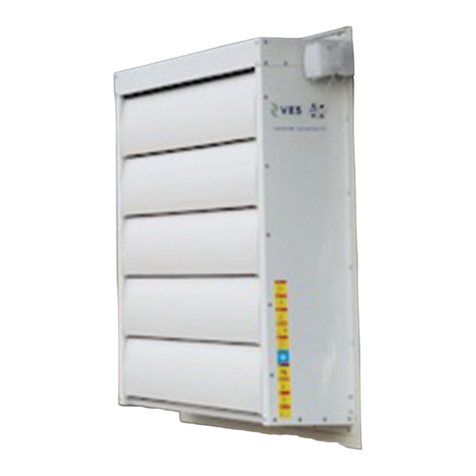
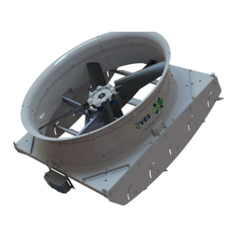
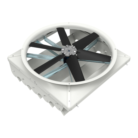
TURNTIDE VES-Artex PPFD72 User manual

VES PPFD72 Fan
Installation Manual
ves-artex.com
1.888.622.2999
SAVE THIS MANUAL FOR FUTURE REFERENCE
PIG-027-AFRD72-01

Table of Contents Table of Contents
Copyright © 2022 ves-artex.com | All Rights ReservedCopyright © 2022 ves-artex.com | All Rights Reserved
Table of Contents
SECTION 1: Pre-installaon
Fan Highlights��������������������������������������������������������������������������������������������������������������������������������������� 1-1
Fan Performance.................................................................................................................................... 1-1
Attachments............................................................................................................................................. 1-2
Inlet........................................................................................................................................................ 1-2
Outlet.................................................................................................................................................... 1-2
Safety Precautions ������������������������������������������������������������������������������������������������������������������������������ 1-3
Safety Alert Key...................................................................................................................................... 1-3
General Safety......................................................................................................................................... 1-3
Unpacking ���������������������������������������������������������������������������������������������������������������������������������������������� 1-4
General....................................................................................................................................................... 1-4
Recommended Tools....................................................................................................................... 1-4
SECTION 2: Mechanical Installaon
PPF Rough Opening���������������������������������������������������������������������������������������������������������������������������� 2-1
PPF ASK Mounting������������������������������������������������������������������������������������������������������������������������������ 2-1
Cross Sectional Width������������������������������������������������������������������������������������������������������������������������ 2-2
Fan Assemblies������������������������������������������������������������������������������������������������������������������������������������� 2-3
Outlet Guard ����������������������������������������������������������������������������������������������������������������������������������������� 2-4
Recommended Tools............................................................................................................................. 2-4
Installation Steps.................................................................................................................................... 2-4
Inside Deector Kit (IDK) ����������������������������������������������������������������������������������������������������������������� 2-4
Recommended Tools............................................................................................................................. 2-4
Installation Steps.................................................................................................................................... 2-4
Inlet Guard��������������������������������������������������������������������������������������������������������������������������������������������� 2-5
Recommended Tools............................................................................................................................. 2-5
Installation Steps.................................................................................................................................... 2-5
Actuated Shutter Kit (ASK) �������������������������������������������������������������������������������������������������������������� 2-5
Recommended Tools............................................................................................................................. 2-5
Installation Steps.................................................................................................................................... 2-5
SECTION 3: Electrical Installaon
Motor Label ������������������������������������������������������������������������������������������������������������������������������������������� 3-1
Motor Wiring ���������������������������������������������������������������������������������������������������������������������������������������� 3-2
Motor Control��������������������������������������������������������������������������������������������������������������������������������������� 3-3
LED Indicators �������������������������������������������������������������������������������������������������������������������������������������� 3-4
Sensors���������������������������������������������������������������������������������������������������������������������������������������������������� 3-4
Shutter Powered Actuator Wiring ������������������������������������������������������������������������������������������������ 3-5
Control Switch......................................................................................................................................... 3-5
Turntide Motor Control Wiring PPF to PPF Shutter Powered Actuator ........................ 3-6
SECTION 4: Operaon and Maintenance
Maintenance Schedule ���������������������������������������������������������������������������������������������������������������������� 4-1
Fan................................................................................................................................................................ 4-1
Wiring ......................................................................................................................................................... 4-1
Blades.......................................................................................................................................................... 4-1
Exhaust Cone and Fan Housing........................................................................................................ 4-2
Outlet Guard............................................................................................................................................ 4-2
Inside Deector Kit (IDK) ................................................................................................................... 4-2
Inlet Guard................................................................................................................................................ 4-2
Actuated Shutter Kit (ASK)................................................................................................................ 4-2
Control........................................................................................................................................................ 4-2
Maintenance Schedule - Attachments ����������������������������������������������������������������������������������������� 4-2
Maintenance Guidelines ������������������������������������������������������������������������������������������������������������������� 4-3
Routine Maintenance ........................................................................................................................... 4-3
Dairy BOS (Barn Operating System) .............................................................................................. 4-4
Dairy BOS is an available app............................................................................................................ 4-4
Replacement Parts������������������������������������������������������������������������������������������������������������������������������ 4-5
Base Fan..................................................................................................................................................... 4-5
Outlet Guard............................................................................................................................................ 4-6
Inside Deector Kit (IDK) ................................................................................................................... 4-7
Inlet Guard................................................................................................................................................ 4-8
Actuated Shutter Kit (ASK)................................................................................................................ 4-9
Troubleshooting���������������������������������������������������������������������������������������������������������������������������������4-10
Warranty ����������������������������������������������������������������������������������������������������������������������������������������������4-11

1-1
Pre-installation
Copyright © 2022 ves-artex.com | All Rights Reserved
VES PPFD fans are designed to inject fresh air into barns, parlors, or holding areas. They are
also great additions to facilities where negative inlets are not enough.
•Reduce static pressure by forcing air into the barn, giving you more air to circulate�
•Use Smart Motor Technology that works with connected technology like VES-Artex Dairy-
BOS (hands off facility and data management).
Fan Performance
Fan Highlights
72” Fan
• Available in 50 & 60 Hz
• Motors have an industry-leading 3-year warranty
• Max RPM: 420
Direct Drive
No Belt Maintenance
Smooth Fiber Reinforced
Blade Assembly
Sturdy and Stays Cleaner
Galvanized Steel Cross Mount
Aerodynamic and Durable
TX Smart Motor Technology
Maximum Efficiency and Connectivity
•Airow: 40900 CFM
• Power Consumption: 2175 Watts
•Efciency: 18.8 CFM/Watts
*Performance data taken at 0 static pressure

1-2
Pre-installation
Copyright © 2022 ves-artex.com | All Rights Reserved
Attachments
Inlet Outlet
Inlet Guard Outlet Guard
Actuated Shutter Kit (ASK) Inside Deector Kit (IDK) - optional

1-3
Pre-installation
Copyright © 2022 ves-artex.com | All Rights Reserved
Safety Precautions
Safety Alert Key
Indicates an imminently hazardous situaon which, if
not avoided will result in death or serious injury.
Indicates a potenally hazardous situaon which, if
not avoided could result in death or serious injury.
Indicates a potenally hazardous situaon which, if
not avoided could result in minor or moderate injury.
Used to address pracces not related to personal
injury.
Read and understand this manual prior to installation or servicing your VES-Artex product.
For the safe handling of VES-Artex products, you will nd the following safety words DANGER, WARNING, CAU-
TION and NOTICE throughout this manual. These will identify safety levels as described below. Failure to obey
the safety measures may result in death, serious injury or damage to the product.
Use best industry practices when handling tools and equipment. When handling VES-Artex products follow all
federal, state, and local safety codes as it related to the work being performed.
General Safety
1. Verify lifting equipment is safe prior to fan handling.
2. Electrocution. Disconnect fan prior to any service.
3. Electrical wiring must be completed by qualied personnel in accordance
with all applicable codes.
4. Verify the electrical system is properly grounded prior to installing fans.
1. Keep hands and objects away from rotating fan blades.
2. Fans with blades rotating below 7 feet (2.3 meters) must be fastened with guards.
3. Heavy load. Handle fans with a safe and secure method.
4. Falling damage. Mount fans with VES-Artex approved hardware.
5. Always wear eye protection when installing and servicing VES-Artex products.
1. Follow all federal, state and local safety codes as it relates to work being performed.
1. Ensure fan(s) are not damaged prior to installation.
2. Ensure all fan parts are accounted for prior to installation.

1-4
Pre-installation
Copyright © 2021 ves.co | All Rights Reserved
Unpacking
General
Do not remove zip es (A) during transportaon and
installaon to prevent equipment damage or personal
injury. See Figure 1-1.
Once a VES-Artex product is received, inspect the
product for any damage. It is recommended that in-
specon occurs immediately, especially if the product
is being installed at a later period of me. If any dam-
age is detected, le a claim with the freight carrier.
Use VES-Artex recommended handling techniques
when moving VES-Artex products. Products damaged
during installaon are not covered under warranty.
Recommended Tools
Bit (#2)
13mm
13mm
2000 lb. cap.
Heavy Liing Equipment
Do not begin disassembling the product unl the
building is ready for fan installaon.
1. Start by removing zip ties and stabilizing packing
material (B& E) using cutting pliers. See Figure 1-1.
Retain packing material for future installation.
2. Keep support brackets (C& D) attached to the fan.
3. Remove the horizontal bracket (F) on each fan.
4. Separate fans individually with a reciprocating saw,
by cutting behind the lower angled bracket (D) and
through the wooden pallet.
A
B
C
C
D
E
A
F
Figure 1-1. Pallet Unpacking
Verify liing equipment is safe prior to fan handling.
5. Once a fan has been separated move the fan to
the installation location. See the 2D barn layouts
to nd these locations provided separately.
Be sure zip es (A) are removed prior to operaon to
prevent equipment damage. See Figure 1-1.
Fan depicted below for demo purposes only.

2-1
Mechanical Installation
Copyright © 2022 ves-artex.com | All Rights Reserved
PPF Rough Opening PPF ASK Mounting
Be sure to follow all dimensions listed in manual or
"Warranty" on page 4-11 will be void. Contact
VES-Artex if you are unsure of dimensions listed.
Mechanical Installation
*Units are inch (cenmeter) unless noted otherwise
** If inside deector kit is install add 3 (7.5)
Fan
Model
A - Rough Opening
Width x Height
B - Min. Horizontal
Frame Width
C - Min. Vertical
Frame Width
D - Fan Flange Side to
Rough Opening
E - Fan Flange Top to
Rough Opening
PPFS72
PPFD72
78 1/2 (199) 4 (10) 4 (10)** 3 1/4 (8) 2 3/4 (7)
PPFS55
PPFD55
59 1/2 (151) 51/2 (14) 4 (10)** 3 1/4 (8) 2 3/4 (7)
PPFV36 40 (101.5) 4 (10) 4 (10)** 2 (5) 2 1/8 (5)
D
E
A
B
C
Measure and mark level lines (see D & E) for proper
posion to mount the fan.

2-2 2-3
Mechanical InstallationMechanical Installation
Copyright © 2022 ves-artex.com | All Rights ReservedCopyright © 2022 ves-artex.com | All Rights Reserved
Fan Model A - Horizontal
Minimum Spacing
between Beams
B - Horizontal
Minimum Center to
Center Distance
C - Horizontal
Minimum Outer
Distance
D - Vertical
Minimum Spacing
between Beams
E - Vertical
Minimum Center to
Center Distance
F - Vertical
Minimum Outer
Distance
PPFS72
PPFD72
10 1/2 (27) 89 (226) 175 1/2 (446) 6 1/2 (17) 85 (216) 171 1/2 (436)
PPFS55
PPFD55
10 1/2 (27) 703/4 (180) 139 (353) 12 1/2 (32) 72 3/4 (185) 144 (366)
PPFV36 10 1/2 (27) 501/2 (128) 98 1/2 (250) 5 (13) 45 (114) 93 (236)
*Units are inch (cenmeter) unless noted otherwise
Fan AssembliesCross Sectional Width
Fan Model A - Overhang B - Minimum
Wall Thickness
C - Deector
Fully Opened
D - PPF ASK (Actuated
Shutter Kit) Opened
Weight (includes ASK)
lb (kg)
PPFS72
PPFD72
24 (61) 8 1/2 (22) 21 (53) 21 (53) 620 (280)
660 (300)
PPFS55
PPFD55
24 (61) 8 1/2 (22) 17 (43) 21 (53) 435 (195)
510 (230)
PPFV36 24 (61) 8 1/2 (22) 17 (43) 18 (48) 180 (80)
*Units are inch (cenmeter) unless noted otherwise
A
B
C
D
A
D
F
E
C
B

2-52-4
Mechanical InstallationMechanical Installation
Copyright © 2021 ves.co | All Rights ReservedCopyright © 2021 ves.co | All Rights Reserved
Outlet Guard
Recommended Tools
Bit (#2)
10mm
Li/Ladder if applicable
Installation Steps
Rough Opening Verication
Prior to install, verify the rough opening is accurate for
the corresponding fan model. See “PPF Rough Open-
ing” on page 2-1 for details.
1. Install screw (B) and washer (C) through wire loop
of guard partially into the top left corner of the fan.
See Figure 2-3.
2. Place the guard (A) onto squared ange. Be sure
guard (A) is centered and squared to the opening.
3. Install top left screw (B), washers (C) and nut (D).
4. Install remaining screws, washers nuts (B) around
guard (A) to secure.
BCD
A
Figure 2-3. Outlet Guard
Inside Deector Kit (IDK)
Recommended Tools
13mm
13mm
13mm
Li/Ladder if applicable
Installation Steps
Rough Opening Verication
Prior to install, verify the rough opening is accurate for
the corresponding fan model. See “PPF Rough Open-
ing” on page 2-1 for details.
1. Install screw (B) through deector (A) partially into
the top left corner of the fan. See Figure 2-4.
2. Place the deector (A) onto squared ange. Be
sure deector (A) is centered and squared to the
opening.
3. Install top right screw (B) fully into the framework.
4. Install remaining screws and anged washers (B)
through deector (A) to secure.
B
A
Figure 2-4. Inside Deector
Inlet Guard
Recommended Tools
4mm hex key or bit
Li/Ladder if applicable
Installation Steps
Rough Opening Verication
Prior to install, verify the rough opening is accurate for
the corresponding fan model. See “PPF Rough Open-
ing” on page 2-1 for details.
1. Install screw (B) and clip (C) around wire loop of
guard partially into the top of the fan. See Figure
2-5.
2. Place the guard (A) onto squared ange. Be sure
guard (A) is centered and squared to the opening.
3. Install top screw (B) and clip (C).
4. Install remaining screws (B) and clips (C) around
guard (A) to secure.
A
C
B
Figure 2-5. Inlet Guard
Actuated Shutter Kit (ASK)
Recommended Tools
13mm
13mm
13mm
Li/Ladder if applicable
Installation Steps
Rough Opening Verication
Prior to install, verify the rough opening is accurate for
the corresponding fan model. See “PPF Rough Open-
ing” on page 2-1 for details.
1. Install screw (B) and washer (C) partially into the
top left corner of the fan. See Figure 2-6.
2. Place the Shutter (A) onto squared ange. Be sure
shutter (A) is centered and squared to the opening.
3. Install top right screw (B) fully into the framework.
4. Install remaining screws (B) and washers (C) around
shutter (A) to secure.
A
B
C
Figure 2-6. Shutter

3-1
Copyright © 2022 ves-artex.com | All Rights Reserved
Electrical Installation
Motor Label
For motor label location (H)see “Motor Control” on page 3.
SMC Motor Controller
HR-SRM Motors
www.softwaremotor.com
WARNING: This SMC Motor Controller will
only operate stated SMC Smart Motor.
Conforms to UL STD 508C
Certied to CSA STD C22.2#274
LISTED
5003619
Made in China
INPUT 3PH 460VAC 60Hz / 4.3A
OUTPUT
MAX HP 3.0 /460VAC
3PH 280-680VDC
MODEL SMC-P05
MOTOR SMC-V03s
AVERTISSEMENT: Ce contrôleur de
moteur SMC doit etre utilisé qu’avec
moteur de la série de intelligent SMC.
TYPE IP55
C
B
A
Figure 3-1. Motor Label Information above for representation only. See below for accurate data.
Motor Label contains information about:
• Motor Control model number (A)
• Motor model number (B)
• Required amps and volts (C)
Be sure that power is disconnect from fan and control
prior to any installaon work.
Read and adhere to all safety warnings.
All electrical work must be done by a cered
electrician.
Verify the electrical system is properly grounded prior
to installing fans.
Input Line Voltage 208/230 V 200/240 V 460 V 400 V
Input Line Current 12.1/10.7 A 10.8/9.5 A 5�3 A 6�3 A
Supply Frequency 60 Hz 50 Hz 60 Hz 50 Hz
Supply Phase 3 Phase
Motor Information

3-2 3-3
Copyright © 2022 ves-artex.com | All Rights ReservedCopyright © 2022 ves-artex.com | All Rights Reserved
Electrical InstallationElectrical Installation
Motor Control
C
ED
B
A
I
GH
F
*Units are inch (cenmeter) unless noted otherwise
Motor Control
Model
A - Depth B - Mounting Hole
Center to Center
C - Width D - Mounting Hole
Center to Center
E - Height
SMC-P05 6 (15) 14 1/4 (36) 16 1/8 (41) 6 7/8 (17) 7 1/2 (19)
TO POWER
TO MOTOR
TO POWER
TO MOTOR
*Point Antenna UP
*
*
Drip Loop
Recommended
Orientaon
Oponal Orientaon
Figure 3-3. Drip Loop
Be sure to create a drip loop in the power line to
prevent water from being introduced to the controller
from fan.
Motor Wiring
TX Motor uses the P05 Motor Control.
Does not include the motor-to-control interconnecting
wires. These must be supplied by the installer.
The Motor is ed with a standard terminal box for
conduit connecon.
Motor to Motor Control wires should be enclosed in
a metallic (rigid or exible) liquid ght conduit which
is properly grounded to prevent interference from the
connecng harness.
12 AWG (2.06mm) WIRE
PROVIDED BY INSTALLER
(7 CONDUCTORS)
SMC
P05
MOTOR CONTROL
3 PHASE
SUPPLY VOLTAGE
P1 P2 P3 P4 P5 P6
GREEN
BLACK
YELLOW
RED
VIOLET
BLUE
BROWN
GREEN
*Color varies by voltage and country.
*
Figure 3-2. Electrical Wiring

3-4
Copyright © 2022 ves-artex.com | All Rights Reserved
Electrical Installation
LED Indicators
Motor Control has three LEDs to indicate various states. Refer to table below for indicator states and their mean-
ing. For location of indicator lights (G) and antenna (F) see “Motor Control” on page 3.
Active
(GREEN)
Fault
(RED)
Indicator
(YELLOW)
Action
ON - - Normal status.
Flicker - -
-Two ashes
every 5 secs
Steady Flash - - Motor not connected. Check motor control-to-motor wiring.
- - Steady Flash Non-critical error detected. Motor can continue to run. Contact
VES-Artex for support is condition continues more than 24 hours.
- ON - Critical fault. Motor will not run. Contact VES-Artex for support.
- - - No power. Power on. Check power supply. Contact qualied electrician for
support.
Sensors
For any information regarding sensor that comes in
sensor package be sure to refer to separate sensor
manual.

4-1
Copyright © 2021 ves.co | All Rights Reserved
Operation and Maintenance
Maintenance Schedule
Before performing any maintenance be sure power is
disconnected from fan.
At no me should you aempt to work on or adjust
the fan while fan is running or the blades are moving.
By aempng to service a fan in operaon, you are
risking the safety of yourself and others around you.
During fan service and cleaning, it is recommended
that you wear gloves to protect your hands from
possible sharp edges.
Do not aempt any repairs on the unit unless you are
competent to do so. Repairs need special tools and
skills. If you are unsure or in any doubt, contact your
dealer for assistance.
Component Timeline Task
Fan Daily Check that all fans are working.
Monthly Start up all the fans and check for irregular noise or vibration.
Wiring 12 months
All electrical work must be done by a cered
electrician.
Check integrity of the electrical wiring. Pay particular attention
to cut or split or loose wiring. Repair or replace as needed.
Blades 6 Months General cleaning: wipe blade surfaces.
To avoid shock injury or catastrophic electrical damage
to VES-Artex products, do not use pressurized water on
motor or control. Introducing pressurized water will void
the warranty.
Inspect blades for any irregularities.
Inspect the hub for signs of metal fatigue or wear.

4-34-2 Copyright © 2021 ves.co | All Rights ReservedCopyright © 2021 ves.co | All Rights Reserved
Operation and MaintenanceOperation and Maintenance
These fans are rated for industrial use and are very
durable under normal circumstances. It is still neces-
sary to inspect the fans carefully, especially before
spring start-up, for any loose, bent or missing parts.
• Report any discrepancies to your local dealer so
replacement parts can be ordered and installed�
• Check carefully that no animals, personnel or
machinery can interfere or come in contact with
the equipment during normal operation�
Routine Maintenance
Check all fasteners/hardware regularly.
Make drive inspections periodically:
• Prevent obstructions from fan inlets and outlets
that haven’t been designed by VES-artex�
Maintenance Guidelines
Component Timeline Task
Fan Housing 6 Months Clear housing of any debris.
General cleaning: clean surface so air can ow over smoothly.
Check hardware for loose connections.
Inspect for damage. Repair or replace.
Outlet Guard 6 Months Clear guard of any debris.
Clean surface from both sides.
Check hardware for loose connections.
Inspect for damage. Repair or replace.
Inside Deector Kit (IDK) 6 Months Clear deector of any debris.
Clean surface so air can ow over them smoothly.
Check hardware for loose connections.
Inspect for damage. Repair or replace.
Inlet Guard 6 Months Clear guard of any debris.
Clean surface so air can ow over them smoothly.
Check hardware for loose connections.
Inspect for damage. Repair or replace.
Actuated Shutter Kit (ASK) 6 Months Clear shutter of any debris.
General cleaning: clean surface of louvers so air can ow over
them smoothly and they rotate freely.
Check hardware for loose connections.
Ensure that rods are properly engaged.
Inspect for damage. Repair or replace.
Control 6 Months Remove dust from heat sink. For motor label location (H)see
“Motor Label” on page 3-<?>.
To avoid shock injury or catastrophic electrical damage
to VES-Artex products, do not use pressurized water on
motor or control. Introducing pressurized water will void
the warranty.
Maintenance Schedule - Attachments
*Initial and date when
maintenance is performed
Date: Date: Date: Date: Date: Date: Date: Date:
Wiring
Blades
Fan Housing
Outlet Guard/Inlet Guard
Inside Deector Kit (IDK)
Actuated Shutter Kit
Control

4-4
Copyright © 2021 ves.co | All Rights Reserved
Operation and Maintenance
Dairy BOS (Barn Operating System)
Dairy BOS is an available app
DairyBOS is the industry’s rst fully integrated barn operating system that controls
every facet of the environment that impacts cow comfort – while also maximizing
animal welfare and sustainability. From ventilation, to lighting, to cooling and beyond,
DairyBOS integrates with VES-Artex products, and a wide variety of other
manufacturer’s products, including fans, soakers, sensors and a variety of other in-
barn equipment. DairyBOS delivers dairy intelligence that increases productivity and
protability while making cows happier and healthier. DairyBOS provides dairies with
real-time, actionable data at their ngertips through any internet-connected device
or smartphone. At VES-Artex, we’re committed to becoming the technology leader
in dairy, innovating the connection of animals, people, physical things, processes, and
decision making on the dairy.
Click links or go to address below for videos about Dairy BOS:
https://vimeo.com/477330208
https://vimeo.com/477330112
https://vimeo.com/508955727/161778750e

4-5
Copyright © 2022 ves-artex.com | All Rights Reserved
Operation and Maintenance
Replacement Parts
Base Fan (105606)
1
6
23
4
7
5
Item Part Number Description Qty
1105306 TX2 Motor 1
2100434 Gusset 4
3105597 Support Bracket 4
4104686 Blade Assembly 1
5100484 Bushing 1
6100189 Housing Section 4
7105824 Support Bracket Stiffener 4

4-6 4-7
Copyright © 2022 ves-artex.com | All Rights ReservedCopyright © 2022 ves-artex.com | All Rights Reserved
Operation and MaintenanceOperation and Maintenance
Outlet Guard
1
2
Item Part Number Description Qty
1105211 Outlet Guard 1
2101528 Hardware Package 1
Inside Deector Kit (IDK)
31
2
Item Part Number Description Qty
1103843 Inside Deector 1
2100309 Hanger, Left and Right, Galvanized 2
3104663 Hardware Kit, PPFS72IDK 1
4103972 Deector assembly (w/end cap and screw) 5

4-8 4-9
Copyright © 2022 ves-artex.com | All Rights ReservedCopyright © 2022 ves-artex.com | All Rights Reserved
Operation and MaintenanceOperation and Maintenance
Inlet Guard
1
Item Part Number Description Qty
1100600 Flat Guard 1
2101542 (Not Shown) Hardware Package 1
Actuated Shutter Kit (ASK)
1
2
4
5
10
9
7
6
8
3
11
12 13
14
15 16
Item Part Number Description Qty
1100321 Right Frame 1
2100952 Insulation, Sound (Right) 1
3100298 Lower Gusset 2
4100954 Insulation, Sound (Bottom) 1
5100318 Bottom Frame 1
6100319 Top Frame 1
7100956 Insulation, Sound (Top) 1
8101767 Wind Guide & Air Guide Plate (with End, Screw and Rubber Seal) 6
9100953 Insulation, Sound (Left) 1
10 100320 Left Frame 1
11 100317 Shell, Actuator 1
12 100297 Bracket, Actuator 1
13 100476 Actuator (with Wire) 1
14 100300 Drive Bracket 1
15 100303 Bracket, Drive 1
16 100322 T Bar 1

4-10
Copyright © 2022 ves-artex.com | All Rights Reserved
Operation and Maintenance
Troubleshooting
Symptom Cause Solution
FAN WILL NOT START Blown or bad fuse or circuit breaker Check fuses and circuit breakers.
Bad connection Check wire connections to motor.
Over or under voltage Check voltage at fan connection.
FAN TOO FAST / SLOW Over or under voltage Check voltage at motor. Ensure motor
is wired for correct voltage.
Setting not correct Check environmental control settings.
FAN MAKES NOISE Loose hardware or attachments Check motor case to make certain all
visible screws are snug.
Check to make certain that all blade
bracket screws are tight.
Check to make sure fan/guards are
secured.
Bad/worn bearing or bent shaft
Debris
Check bearing shaft to ensure blade
spins freely with no noise
FAN WOBBLES/VIBRATES Loose hardware Check that all blade paddles are
screwed rmly to the spyder.
Damaged blades
Debris
Run fan without blade, if motor does
not wobble, then motor is not defec-
tive but the blades may be damaged.
Bad/worn bearing Check for worn bearing shaft.

4-11
Copyright © 2022 ves-artex.com | All Rights Reserved
Operation and Maintenance
07/01/2020 This warranty replaces all previously printed or stated warranties. This warranty may change without notice.
Warranty
LIMITED WARRANTY & RETURN POLICY
THERE ARE NO WARRANTIES WHICH EXTEND
BEYOND THE DESCRIPTION ON THE FACE HEREOF.
ONE-YEAR LIMITED WARRANTY
VES Environmental Solutions, LLC. (VES) products are
warranted to the original purchaser (“purchaser” is dened
as person or company who received an invoice from VES
for purchase of goods) against defects in workmanship or
materials, under normal use for one year after original date
of purchase unless specied in any of the warranties listed
below. Any part which is determined to be defective in mate-
rial or workmanship and returned to a preauthorized service
location (as VES designates with shipping costs prepaid
by purchaser) will be, as the exclusive remedy, repaired or
replaced at VES’s option. For limited warranty claim proce-
dures, see “Prompt Disposition” below. This limited warranty
gives the purchasers specic legal rights which vary from
jurisdiction to jurisdiction. To le a warranty claim or for the
return procedure, please see the “Prompt Disposition” or
“Returns” sections below.
SPECIFIC LIMITED WARRANTIES
3 Years on Turntide Direct Drive Motor
2 Years VESC Control Series, Phason Controls, Turntide
DirectDrive Controls, and Variable Frequency Drives (Manu-
facturer Warranty, Prorated)
2 Years on Steel (Prorated)
2 Years on Variable Speed Motors
3 Years on Polycarbonate Sheets
5 Years on Lighting
5 Years on Rubber Flooring (Mfg Warranty Prorated)
5 Years Industrial Ceiling Fans
10 Years on all 36”, 50”, 55” & 72” Fiberglass Housings
5 Years on all 50”, 55” & 72” Poly Blades or Aluminum Blades
90 Days on Phason Accessories, Kits, Replacement Parts and
Software
Curtain Drive Units and Parts
1 Year on Motor
2 Years on Lock Drives Drive Units and parts, excluding the
Motor (Mfg Warranty Prorated)
LIMITATION OF LIABILITY
To the extent allowable under applicable law, VES’s liabil-
ity for consequential and incidental damages is expressly
disclaimed. VES does not refund any costs related to the
installation, removal, or time associated with work done
on product(s) or labor related thereto. VES’s liability in all
events is limited to, and shall not exceed, the purchase price
paid. Any variation from this limitation must be exclusively
approved in writing by an ofcer of VES.
DISCLAIMER: A diligent effort has been made to provide
product information and illustrate the products accurate-
ly. However, such information and illustrations are for the
sole purpose of identication, and do not express or imply a
warranty that the products are merchantable or suitable for
a particular purpose, or that the products will precisely con-
form to the illustrations or descriptions. Except as provided
herein, no warranty or afrmation of fact, expressed or im-
plied, (other than as stated in the “limited warranty” section
above) is made or authorized by VES, unless in writing by an
ofcer of VES. Certain aspects of disclaimers or limitations
on warranties may not be applicable to consumer products
in certain jurisdictions; in such cases, such aspects of dis-
claimers or limitations hereunder may not be applicable to
purchasers located in those jurisdictions.
TECHNICAL ADVICE AND
RECOMMENDATIONS DISCLAIMER:
Notwithstanding a past practice, trade custom, or any other
related dealings, sales shall not include the furnishing of
technical advice, assistance or system design. VES assumes
no obligation or liability on account of any unauthorized rec-
ommendations, opinions, or advice as to the choice, installa-
tion, or use of products.
PRODUCT SUITABILITY: Codes and regulations governing
sales, construction, installation, and/or use of products for
certain purposes may vary from jurisdiction to jurisdiction.
While attempts are made to substantiate that VES products
comply with such codes, VES cannot guarantee compliance
and, therefore, cannot be responsible for how the product is
installed or used. Before purchase and use of a product, the
purchaser should review the product applications, as well
as all applicable national and local codes and regulations, to
be certain that the product, installation, and use will comply
with any corresponding codes and regulations.
Continued on next page...
Table of contents
Other TURNTIDE Fan manuals
Popular Fan manuals by other brands

THOMSON
THOMSON THST21DE instruction manual

Casablanca
Casablanca Coletti 55054 owner's manual

NuAire
NuAire SLIMAIRE installation manual

RenewAire
RenewAire EV130 SERIES Installation, operation & maintenance manual

Home Decorators Collection
Home Decorators Collection FELDNER 56055 Use and care guide

Sharp
Sharp PJ-TA181 Service manual

Timberk
Timberk T-DF1202 instruction manual

Apriaire
Apriaire 8140 Installation and operation manual

Bimar
Bimar VSL1520 Instruction booklet

RUSTA
RUSTA 907511880101 manual

Central Machinery
Central Machinery 97762 Owner's manual and safety instructions

Helios
Helios KWL 45 ISL Installation and operating instructions