Tutco SureHeat F038821 User manual

OPERATING MANUAL
Threaded Inline Air Heaters
FOR SAFETY AND LONG HEATER LIFE,
CAREFULLY READ THIS MANUAL BEFORE USE.
Threaded Inline Air Heaters

THANK YOU FOR CHOOSING A THREADED INLINE AIR HEATER
Thank you for purchasing a TUTCO SureHeat process air heating product. Our heaters
efficiently heat air or inert gases to meet the needs of the most demanding applications using
our innovative Serpentine™ Technology— ensuring better heat transfer, faster, and higher
temperatures and a heating element life unmatched in the marketplace.
TUTCO THREADED INLINE AIR HEATERS
Stainless Steel threaded heaters for heating high-pressure air or inert gases up to 1400°F (760°C).
Sizes include 3/8”, 1/2“, 1-1-4” and 2-1/2” diameter, with wattages from 1.6 to 24 Kilowatts.
There are two (2) body styles. Body Style A has power feed thru posts and unit is considered
leak-proof to 150PSI. Body Style B has 12” flexible fiberglass sleeved power wires and rated
to 150 PSI (10 BAR), but will have slight air leakage through the power wire strands. If operated
correctly, the heater will operate continuously for 5000 hours or longer.
HOT AIR TOOL HEATER SPECIFICATIONS
Maximum Inlet Air Pressure 150 PSI (10 BAR)
Maximum Inlet Air Temperature 900°F (482°C) for Body Style A
200°F (93°C) for Body Style B
Maximum Exit Air Temperature 1400°F (760°C) (see page 9 for Performance Curves)
* For Body Style B Heaters there will be a slight air leakage through power wire strands
*For Body Style A Heaters, the torque specification for the power connections is 20 lb-in (2.26 N-m)
GENERAL INFORMATION
Environmental Conditions:
Ambient Temperature 32°F to 104°F (0°C to 40°C)
Humidity 0% to 95% R.H.
Ventilation:
Use in a well-ventilated area away from excess dust, dirt, and moisture.
Cleaning:
With unit OFF and unplugged, exterior surfaces may be wiped clean using a dry, lint-free cloth.
Protective Grounding:
Each heater comes with a convenient grounding stud and hardware located at the inlet of the
heater for protective means of earthing.
2

WARNINGS!
TUTCO SureHeat Process Air Heaters contain high watt-density elements and must be
controlled carefully to prevent element failure.
IMPORTANT: Be sure to read and understand this operating manual before turning the
system ON. Follow all checklists shown in the manual. Failure to do so can cause a heat-
er failure and may void warranty.
ONLY qualified individuals should install and service this heater and related controls.
Do not hesitate to contact TUTCO SureHeat with any questions
Phone: 603-418-7662
E-Mail: [email protected]
ELECTRICAL SHOCK HAZARD!
Follow all applicable electrical codes and use proper wiring.
BURN/FIRE/EXPLOSION HAZARD!
For use with Air or Inert Gases Only -
Do not use with or near explosive or reactive gases.
Avoid contact with the surface of the heater especially the air exit-end during or soon
after operation. Depending on the installation location customer may need to install
protective screen or guard to prevent injury to personnel and comply with OSHA code.
DO NOT USE NEAR VOLATILE OR COMBUSTIBLE MATERIALS.
3

4
PRECAUTIONS
Caution: Do not operate heater without air flowing
1. Use filtered air. Avoid grease, oil, or oil vapors, corrosive or reactive gases which will
damage heater.
Note: When using compressed air a pressure reduction valve and an oil & water separation unit
should be installed to avoid contaminating the heater and reduce heater life.
2. Operate at safe voltages as shown on the Performance Curves (see page 8). Excess voltage
will cause premature failure.
3. Always have sufficient airflow through the heater before applying power. Otherwise element
will overheat very quickly, and burn out. Note: A thermocouple cannot detect temperatures if
there is no flow – turn on flow before applying power, even when a controller with a
thermocouple is being used.
4. Use Style ‘A’ threaded inline heaters for absolute leak-proof applications (150 PSI). Style ‘B’
threaded inline heaters will have some air leakage through the lead wires.
5. Use phase angle fired power controllers. On-Off controllers may shorten heater life (or
burnout element).
6. For closed-loop control, use exposed junction type “K” thermocouple located within one inch
of the heater exit.
7. For closed-loop control, use a temperature controller with a fast sampling period (<500ms)
and minimal overshoot.
8. The torque specification for Style A heater power connections is 20 lb-in (2.26 N-m).

EXTENDING THE LIFE OF YOUR HEATERS ELEMENT
The life of a TUTCO SureHeat heater is directly based on the temperature of the heater’s filament
wire. Most failures are due to low air flow or damage associated to power control and voltage ramp
up rates which elevate the element wire temperature above 2200ºF (1204ºC). TUTCO SureHeat
Serpentine elements heat up very fast and good control is necessary to avoid overshoot. A
thermocouple has been integrated into the heater to allow you to monitor and maintain the proper
filament temperature and extend the life of your heater’s element wire.
Tips
• Ensure airflow is on before voltage is applied to heater.
• Use a temperature controller with 200ms or quicker cycle time.
• Use a power controller (SCR/SSR) equally as fast to regulate voltage to the heater.
5
Style “B”Style “A”

6
HEATER MODEL AND PARTS LIST
F038821 A 3/8” 1600 170 9.4
F038822 B* 3/8” 1600 170 9.4
F038823 A 1/2” 4000 220 18.2
F038824 B* 1/2” 4000 220 18.2
F038825 A 1-1/4” 6000 220 27.3
F038826 B* 1-1/4” 6000 220 27.3
F077065 A 1-1/4” 8000 240 33.3
F077028 B* 1-1/4” 8000 240 33.3
F063007 B* 2-1/2” 18000 240 75 (1PH) / 44 (3PH)
F076418 B* 2-1/2” 18000 480 21.7 (3PH only)
F074439 B* 2-1/2” 24000 240 58 (3PH only)
Part
Number
Body
Style
Maximum
Voltage
Maximum
Amperage
Maximum
Temperature
Maximum
Wattage
Diameter
1200˚F
(649˚C)
1400˚F
(760˚C

DIMENSIONS/MOUNTING
NOTE: The inlet side of the heater is located where the leads/power feedthrus come out of the housing. Failure to
install the heater in its proper orientation can result in heater damage and is not covered under the manufacturer’s
warranty.
7

INSTALLATION Caution: DO NOT Operate Heater Without Air
8
MOUNT HEATER
WIRE HEATER BASED ON INSTRUCTIONS FOR MODEL
CONNECT AIR SOURCE TO HEATER
THERMOCOUPLE PLACEMENT
If a thermocouple is used external to the heater instead of the internal thermocouple,
ensure that it is located within one inch of the heater exit.
WARNING: THE INLET AIR/GAS SIDE OF THE HEATER IS LOCATED CLOSEST TO WHERE THE POWER
FEED-THRU CONNECTIONS ARE MADE. INSTALLING THE HEATER IN THE WRONG ORIENTATION WILL
DAMAGE THE HEATER AND CAN CREATE ADDITIONAL HAZARDS AS A RESULT.
MOUNT
HEAT
ER
T
O
HEATER

INSTALLATION
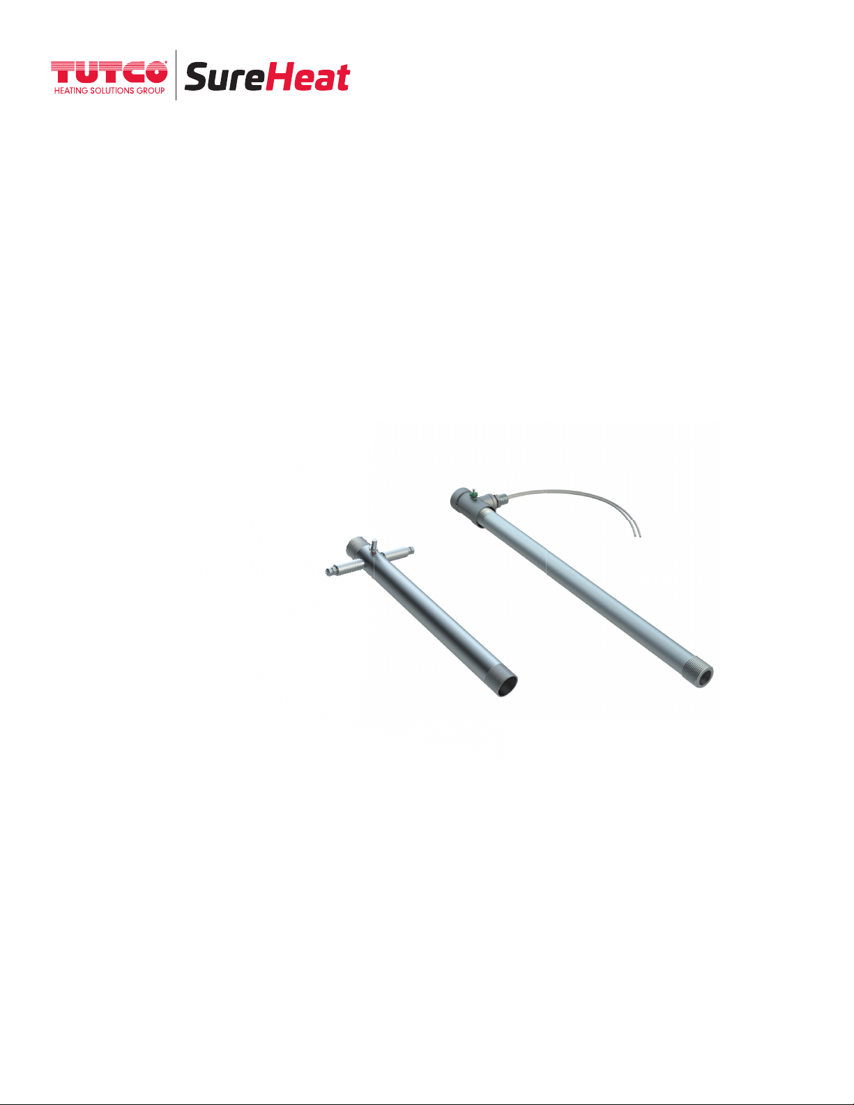
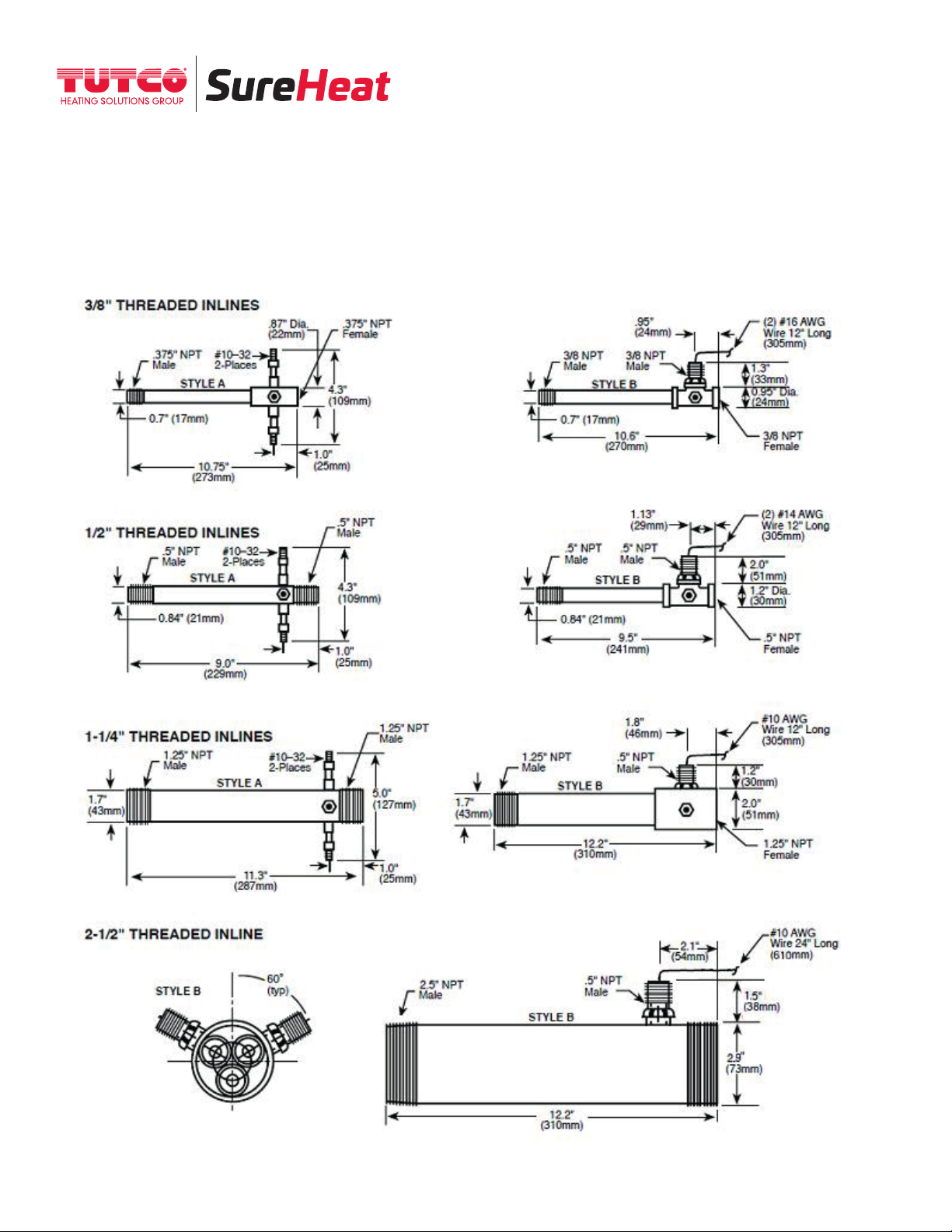
For 3/8”, 1/2”, & 1-1/4” HEATER ONLY (#F038821, F038822, F038823, F038824, F038825 & F038826):
1. There are two (2) feed-thrus on the heater. Connect one power lead to one heater electrical feed-thru
(ƒ one lead wire) and connect the other power lead to the other electrical feed-thru (or the other lead wire).
2. Connect the ground wire to the green grounding nut on the heater body.
3. Connect the air source to the heater.
4. If a thermocouple is used, ensure that it is located within one inch from the heater exit.
For 2-1/2” HEATER ONLY (#F063007): 18 kW - 240 Volt - 1Ø Operation:
Note: Running this heater at 240 Volts 1Ø will draw up to 75 Amps
1. The heater has two (2) set of power feed-thrus with three (3) wires (marked 1, 2, or 3) coming out of it.
2. Connect one side from the power to all three (3) leads that exit one (1) feed-thru (1, 2, and 3 together).
3. Connect the other side of the power to all three (3) leads that exit the second feed-thru (1, 2, and 3 together).
4. Make sure the heater is properly grounded.
5. Connect the filtered air source to the heater.
6. If a thermocouple is used, ensure that it is located within one inch from the heater exit.
FOR 2½” HEATER ONLY (#F063007 & F074439): 18 & 24 kW - 240 Volt – 3Ø Operation:
1. The heater has two (2) set of power feed-thrus with three (3) wires (marked 1, 2, or 3) coming out of it.
2. Connect the elements in a standard delta configuration. (Connect one (1) power lead to each of the
following pairs: 1-2, 2-3, 3-1).
3. Check resistance leg to leg. They should be approximately within 0.1 ohms of each other if wired properly.
4. Make sure the heater is properly grounded.
5. Connect the filtered air source to the heater.
6. If a thermocouple is used, ensure that it is located within one inch from the heater exit.
FOR 2½” HEATER ONLY (#F076418): 18 kW - 480 Volt – 3Ø Operation:
1. The heater has one (1) set of three (3) wire leads (marked 1, 2, or 3) coming out of it.
2. Connect the leads directly to the output of the power controller for standard 480V 3Ø operation.
3. Check resistance leg to leg. They should be approximately within 0.1 ohms of each other if wired properly.
4. Make sure the heater is properly grounded.
5. Connect the filtered air source to the heater.
6. If a thermocouple is used, ensure that it is located within one inch from the heater exit.
9

10
TYPICAL WIRING
1Ø Heater with Closed Loop Control
3Ø Heater with Closed Loop Control
AC
AC
3Ø Disconnect
L3 L2 L1
H1 H2 H3
TC –
TC + Output
+ –
Temp
Control
Power
Control
Heater
–
+
H1
H2
H3
G
AC
AC
L1 L2
L1 H1
TC –
TC + Output
+ –
Temp
Control
Power
Control
Heater
– +
H1
H2
G

OPERATION
11
12
REFERENCE PERFORMANCE CURVES
Beginning on page 11 prior to operating heater.
34
TURN ON AIR
Set pressure or flow to desired operating level.
SET DESIRED TEMPERATURE
1 2
TURN OFF MAIN POWER
3
CONTINUE AIR FLOW
Allow air to continue to flow for a minimum of 1 minute
or until exit air temperature is 300°F/150°C or less for
safety. Continue airflow longer as necessary to prevent
burn hazard to personnel.
TURN OFF AIR TO SYSTEM
5
CONTROL AIRFLOW
Ensure airflow is on before voltage is applied to heater. The heater should NOT be operated with an airflow of less that 1 SCFM
or 60 SCFH may cause the heater’s element to overheat too quickly and burnout.
6
CLOSED OR OPEN-LOOP SYSTEM
If using a closed loop system, turn on power to the temperature and power controller, then set the desired temperature
on the temperature controller. If using an open loop system, increase power to the heater through the power controller
until the desired temperature is attained.
START-UP
SHUT-DOWN
X
X
ENERGIZE MAIN POWER LINE
Via disconnect switch or circuit breaker on control cabinet.
2
2

12
PERFORMANCE CURVES
HOT AIR TOOLS MAXIMUM PERFORMANCE CURVE
The attached performance curves show exit air temperatures at different airflows and voltages.
Pressure readings (longer dashed lines) are measured at the inlet to the heater with no entrance or
exit restrictions. Solid lines indicate safe, normal-life operating conditions. The shorter dash lines
indicate marginal, shorter-life operating conditions leading to premature burnout. With a known flow
(or pressure) at the heater entrance, follow the flow (or pressure) line across until it meets the desired
temperature curve. Drop a line straight down to intersect the x-axis. This point, along the “Heater
volts – true RMS” axis, represents the voltage required to generate the desired exit air temperature
at the chosen flow rate (inlet pressure).

13

14

15

16
TROUBLESHOOTING AND HEATER REPLACEMENT
1. Note that “TYPICAL” Element Life is APPROXIMATELY 5000 hours. This is based on heater
element operating at or below temperatures shown on PERFORMANCE CURVE. In addition to
normal end of life, elements can fail due to mechanical damage, or problems with the
control system.
2. If an element has failed prematurely, it should be inspected to determine the cause of the
element failure.
3. When replacing or troubleshooting heaters, turn off power to the system and be sure to follow
lock-out/tag-out procedures.
a. For Troubleshooting Heater
i.) Use multi-meter to check continuity between:
1. Power terminals H1-H2 (for 1Ø) or H1 to H2, H2 to H3 and H1 to H3
(for 3Ø)
2. Thermocouples positive (+ yellow) to negative (- red)
ii.) If there is continuity on all above tests, check system wiring:
1. Crossed thermocouple wires.
2. Reversed thermocouple wire polarity – Note: RED is NEGATIVE ( - ).
3. Verify inlet air temperature is below set point on INLET
TEMPERATURE controller.
iii.) If there is no continuity on any test, then contact your local TUTCO SureHeat
representative for assistance.
4. Remove entire heater assembly from system. Internal components are typically not replaceable.
5. Reconnect thermocouples, power and ground wires for new/replacement heater.
6. Attach any covers and operate heater per operating manual.

17
LIMITED WARRANTY
TUTCO SureHeat warrants that all products to be delivered hereunder will be free from defects in
material and workmanship at the time of delivery. TUTCO SureHeat’s obligation under this warranty
shall be limited to (at its option) repairing, replacing, or granting a credit at the prices invoiced at the
time of shipment for any of said products. This warranty shall not apply to any such products which
shall have been repaired or altered, except by TUTCO SureHeat, or which shall have been subjected.
TUTCO SureHeat shall be liable under this warranty only if (A) TUTCO SureHeat receives notice of
the alleged defect within sixty (60) days after the date of shipment; (B) the adjustment procedure
hereinafter provided is followed, and (C) such products are, to TUTCO SureHeat’s satisfaction,
determined to be defective.
THE WARRANTY SET FORTH IN THE PRECEDING PARAGRAPH IS EXCLUSIVE AND IN LIEU OF
ALL OTHER WARRANTIES, EXPRESS OR IMPLIED, INCLUDING, WITHOUT LIMITATION, ANY
IMPLIED WARRANTY OF FITNESS FOR A PARTICULAR PURPOSE OR OF MERCHANTABILITY.
The information contained in this manual is based on data considered to be true and accurate.
Reasonable precautions for accuracy has been taken in the preparation of this manual, however
TUTCO SureHeat assumes no responsibility for any omissions or errors, nor assumes any liability
for damages that may result from the use of the product in accordance with the information
contained in this manual.
Please direct all warranty/repair requests or inquiries to the place of purchase, and provide the
following information, in writing:
(A) Order number under which products were shipped
(B) Model/Serial Number of product
(C) Reason for rejection
PRODUCTS CAN NOT BE RETURNED TO TUTCO SUREHEAT WITHOUT AUTHORIZATION.
Replacement, repair, or credit for products found to be defective will be made by the place of pur-
chase. All products found to be not defective will be returned to the Buyer; transportation charges
collect or stored at Buyers expense.

Electric Industrial Air Heaters for
Demanding High-Temperature Applications
The technical data and specifications supplied in this operating manual are subject to
change without prior notice. Contact TUTCO SureHeat for additional assistance.
603-418-7662
22 Industrial Drive Exeter, NH 03833 USA
Aerospace Automotive 3D Printing Electronics Medicine Packaging Printing Plastics Textiles
This manual suits for next models
10
Table of contents
Other Tutco SureHeat Heater manuals
Popular Heater manuals by other brands

Inforesight
Inforesight Solaira ICR H1 Series Reference manual

Thermoscreens
Thermoscreens T600 Series Installation and operating instructions

Ravanson
Ravanson HH-01 user manual

Warmtech
Warmtech WTCAC50R Original instructions

Varma
Varma WR2000 operating instructions

Toyotomi
Toyotomi Zibro RS-220 operating manual