Tutco SureHeat Serpentine II User manual

OPERATING MANUAL
Serpentine II
and Serpentine VI
Air Heaters

THANK YOU FOR CHOOSING A SERPENTINE HEATER
SERPENTINE II and VI
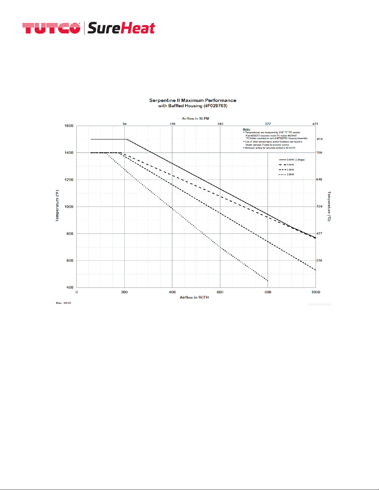
Compact and efficient process air/inert gas heater, capable of producing exit temperatures up to
1400°F (760°C) with standard elements, and up to 1500°F (815°C) with the “2-Stage” elements.
The heater unit consists of two parts - a replaceable serpentine-coil electric heater element,
which fits into a stainless steel “triple-pass” exchanger housing. This special housing uses the
incoming air to cool the outer shell prior to passing through the heater element. This not only
minimizes radiant heat losses but provides a cool outer shell, to minimize burn injury for
operators who accidentally contact the heater. Two heater sizes are available; the Serpentine II
(wattages from 2000 to 3600W) and the Serpentine VI (wattages from 5000 to 8000W). If
operated correctly, element life will be greater than 5000 hours.
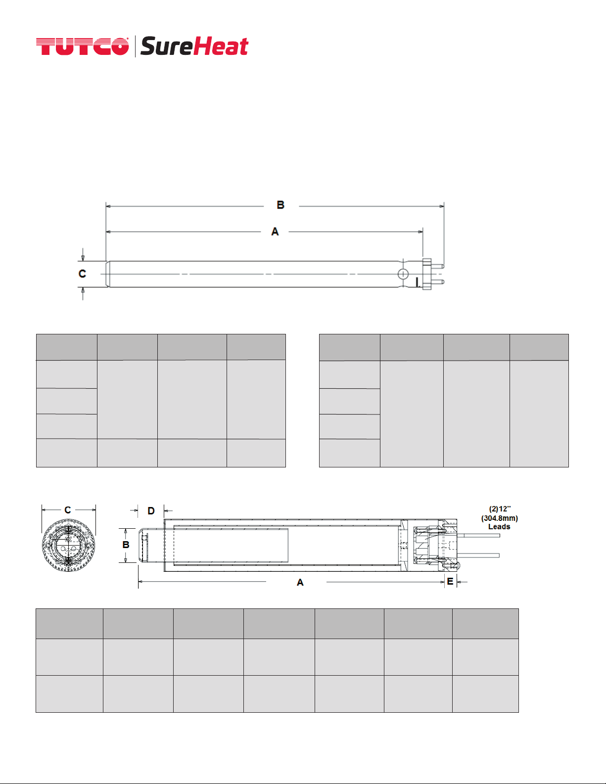
SERPENTINE HEATER SPECIFICATIONS
Maximum Inlet Air Pressure 25 PSI (1.7 BAR)*
Maximum Inlet Air Temperature 200°F (93°C)
Maximum Exit Air Temperature 1400°F (760°C) Single Stage
1500°F (815°C) Two-Stage
(see page 10 for Performance Curves)
Minimum Airflow (Recommended) 60 SCFH (28 SLPM) for Serpentine II models
120 SCFH (57 SLPM) for Serpentine VI models
GENERAL INFORMATION
Environmental Conditions:
Ambient Temperature 32°F to 104°F (0°C to 40°C)
Humidity 0% to 95% R.H.
Ventilation:
Use in a well-ventilated area away from excess dust, dirt, and moisture.
Cleaning:
With unit OFF and unplugged, exterior surfaces may be wiped clean using a dry, lint-free cloth.
Protective Grounding:
Each heater comes with a convenient grounding stud and hardware located at the inlet of the
heater for earth ground.
2

WARNINGS!
TUTCO SureHeat Process Air Heaters contain high watt-density elements and must be
controlled carefully to prevent element failure.
IMPORTANT: Be sure to read and understand this operating manual before turning the
system ON. Follow all checklists shown in the manual. Failure to do so can cause a heat-
er failure and may void warranty.
ONLY qualified individuals should install and service this heater and related controls.
Do not hesitate to contact TUTCO SureHeat with any questions
Phone: 1-800-258-8290
E-Mail: [email protected]
ELECTRICAL SHOCK HAZARD!
Follow all applicable electrical codes and use proper wiring.
BURN/FIRE/EXPLOSION HAZARD!
For use with Air or Inert Gases Only -
Do not use with or near explosive or reactive gases.
Avoid contact with the surface of the heater especially the air exit-end during or soon
after operation. Depending on the installation location customer may need to install
protective screen or guard to prevent injury to personnel and comply with OSHA code.
DO NOT USE NEAR VOLATILE OR COMBUSTIBLE MATERIALS.
3

4
HEATER MODELS AND PARTS LIST
Serpentine II Elements (used with Housing/Exchanger Part #F029763)
* Temperatures are measured by 3/16” “K” T/C sensor Part #F039272 mounted inside TC holder #F029485 TC Holder mounted on exit of #F029763 Housing Assembly
• Use of other sensor types and/or locations can result in heater damage if used for process control.
• Minimum airflow for accurate control is 60 SCFH (28 SLPM)
• Maximum air temperature is as listed in table above - Operating above this will void warranty
Serpentine VI Elements (used with Housing/Exchanger Part #F057088)
* Temperatures are measured by 3/16” “K” T/C sensor Part #F039272 mounted inside TC holder #F040299 TC Holder mounted on exit of #F057088 Housing Assembly
• Use of other sensor types and/or locations can result in heater damage if used for process control.
• Minimum airflow for accurate control is 120 SCFH (57 SLPM)
• Maximum air temperature is as listed in table above - Operating above this will void warranty
Part
Number
F029765
F029766
F029767
F060418
Maximum
Watts
2000
2800
3600
3600
(2-Stage)
Maximum
Volts
240
240
240
240
Maximum
Amps
8.3
11.7
15.0
15.0
Maximum
Pressure (PSI)
25
25
25
25
Maximum
Temperature*
1400ºF / 760ºC
1400ºF / 760ºC
1400ºF / 760ºC
1500ºF / 815ºC
Part
Number
F040291
F040292
F061429
F056548
Maximum
Watts
5000
6000
6000
(2-Stage)
8000
Maximum
Volts
240
240
240
240
Maximum
Amps
20.8
25.0
25.0
33.3
Maximum
Pressure (PSI)
25
25
25
25
Maximum
Temperature*
1300ºF / 705ºC
1400ºF / 760ºC
1500ºF / 815ºC
1400ºF / 760ºC

DIMENSIONS/MOUNTING
NOTE: The inlet side of the heater is located where the leads/power feedthrus come out of the housing.
Failure to install the heater in its proper orientation can result in heater damage and is not covered under
the manufacturer’s warranty.
Heater Cartridge:
Serpentine II Elements Serpentine VI Elements
Housing Exchanger:
5
A
7.69”
(195mm)
8.13”
(206mm)
B
7.69”
(195mm)
8.13”
(206mm)
C
0.63”
(16mm)
0.63”
(16mm)
A
10.25”
(260mm)
B
10.88”
(276mm)
C
1.25”
(32mm)
Part
Number
Serpentine II
F029763
Serpentine VI
F057088
A
9.63”
(245mm)
12.38
(314mm)
B
0.70ӯ
(18mm)
1.38ӯ
(35mm)
C
1.50ӯ
(38mm)
2.12ӯ
(54mm)
D
1.00”
(25mm)
1.00”
(25mm)
E
0.38”
(9.5mm)
0.50”
(13mm)
Air Inlet
FNPT
0.375”
(9.5mm)
0.750”
(19mm)
Part
Number
F040291
5.0kW
F040292
6.0kW
F061429
6.0kW 2-Stage
F056548
8.0kW
Part
Number
F029765
2.0kW
F029766
2.8kW
F029767
3.6kW
F060418
3.6kW

PRECAUTIONS
1. Use filtered air. Avoid grease, oil, or oil vapors, corrosive or reactive gases which will damage heater.
2. Operate at safe voltages as shown on the Performance Curves (see page 8). Excess voltage will
cause premature failure.
3. Always have sufficient airflow through the heater before applying power. Otherwise element will
overheat very quickly, and burn out. NOTE: A thermocouple cannot detect temperatures if there is
no flow – turn on flow before applying power, even when a controller with a thermocouple is
being used.
4. Use phase angle fired power controllers. On-off controllers may shorten heater life
(or burnout element).
5. For closed-loop control, use exposed junction type “K” thermocouple within one inch of the
heater exit.
6. For closed-loop control, use a temperature controller with a fast sampling period (500ms)
and minimal overshoot.
6

CONNECT GROUNDING WIRE
Connect the ground wire to the green grounding nut on the housing assembly.
CONNECT AIR SOURCE TO HEATER
Connect the filtered air source to the heater.
OPTIONAL EXTERNAL THERMOCOUPLE PLACEMENT
If a thermocouple is used, ensure that it is located within one inch from the heater exit.
Tutco SureHeat recommends using an exposed junction type K thermocouple like
Part # F039272. Contact Tutco SureHeat for specifications.
MOUNT HEATER
Securely mount the heater.
1
2
3
4
WARNING: THE INLET AIR/GAS SIDE OF THE HEATER IS LOCATED CLOSEST TO WHERE
THE POWER FEED-THRU CONNECTIONS ARE MADE. INSTALLING THE HEATER IN THE
WRONG ORIENTATION WILL DAMAGE THE HEATER AND CAN CREATE ADDITIONAL
HAZARDS AS A RESULT.
7
INSTALLATION Caution: DO NOT Operate Heater Without Air

TYPICAL WIRING
7
AC
AC
L1 L2
L1 H1
TC –
TC + Output
+ –
Temp
Control
Power
Control
Heater
+ –
H1
H2
G
8

OPERATION
1 2
REFERENCE PERFORMANCE CURVES
Beginning on page 10 prior to operating heater.
34
TURN ON AIR
Set pressure or flow to desired operating level.
SET DESIRED TEMPERATURE
1 2
TURN OFF MAIN POWER
3
CONTINUE AIR FLOW
Allow air to continue to flow for a minimum of 1 minute
or until exit air temperature is 300°F/150°C or less for
safety. Continue airflow longer as necessary to prevent
burn hazard to personnel.
TURN OFF AIR TO SYSTEM
5
CONTROL AIRFLOW
Ensure airflow is on before voltage is applied to heater. The heater should NOT be operated with an airflow of less that
1 SCFM or 60 SCFH may cause the heater’s element to overheat too quickly and burnout.
6
CLOSED OR OPEN-LOOP SYSTEM
If using a closed loop system, turn on power to the temperature and power controller, then set the desired temperature
on the temperature controller. If using an open loop system, increase power to the heater through the power controller
until the desired temperature is attained.
START-UP
SHUT-DOWN
X
X
ENERGIZE MAIN POWER LINE
Via disconnect switch or circuit breaker on control cabinet.
9

10
PERFORMANCE CURVES
SERPENTINE II ELEMENTS
The performance curves on the following pages show exit air temperatures at different airflows and
voltages. Pressure readings (longer dashed lines) are measured at the inlet to the heater with no
entrance or exit restrictions. Solid lines indicate safe, normal-life operating conditions. The shorter
dash lines indicate marginal, shorter-life operating conditions leading to premature burnout. With
a known flow (or pressure) at the heater entrance, follow the flow (or pressure) line across until it
meets the desired temperature curve. Drop a line straight down to intersect the x-axis. This point,
along the “Heater volts – true RMS” axis, represents the voltage required to generate the desired
exit air temperature at the chosen flow rate (inlet pressure).
8

11
9

10
12

SERPENTINE VI ELEMENTS
13

14

15

16
TROUBLESHOOTING AND HEATER REPLACEMENT
1. Note that “TYPICAL” Element Life is APPROXIMATELY 5000 hours. This is based on heater
element operating at or below temperatures shown on PERFORMANCE CURVE. In addition to
normal end of life, elements can fail due to mechanical damage, or problems with the control system.
2. If an element has failed prematurely, it should be inspected by SureHeat to determine the cause
of the element failure.
3. When replacing or troubleshooting heaters, turn off power to the system and be sure to follow
lock-out/tag-out procedures.
a. For Troubleshooting Heater
i.) Use multi-meter to check continuity between:
1. Power terminals H1 to H2
2. Thermocouples positive (+ yellow) to negative (- red)
ii.) If there is continuity on all above tests, check system wiring:
1. Crossed thermocouple wires.
2. Reversed thermocouple wire polarity – Note: RED is NEGATIVE ( - ).
3. Verify inlet air temperature is below set point on INLET
TEMPERATURE controller.
iii.) If there is no continuity on any test, then contact your local TUTCO SureHeat
representative for assistance.
4. Remove entire heater assembly from system. Internal components are typically not replaceable.
5. Reconnect thermocouples, power and ground wires for new/replacement heater.
6. Attach any covers and operate heater per operating manual.

PROPER CONTROL SETUP
• TUTCO SureHeat process air heaters contain high watt-density elements and must be
controlled carefully to prevent element failure.
• Sudden applications of power can damage heater and void warranty.
• Following each of these guidelines will help to ensure safe heater operation.
4 Start the heater with a 0º (F or C) Set-Point (SV): This will ensure the output signal to the
power control starts off low (0% output) before the contactor is engaged and immediately applying
full power.
4 Use proper closed loop control (PID) settings. TUTCO SureHeat typically uses the following
PID; Proportional (P), Integral (I) and Derivative (D); settings as a starting point for stable temperature
control. Some manual tuning may be required for more precise control.
Description: Range: Default:
(P) roportional 90-250 131
(I) ntegral 8-20 9
(D) erivative 0-2 2
Scan/Cycle Rate < 500mSec 200mSec
4 Incorporate a Ramp Rate for the start-up of the heater. The slower you ramp to your final
set-point the less overshoot and problems you will have. Typically TUTCO SureHeat heaters should
be ramped up over a period of several minutes. The following are recommended ramp rates based
on final temperature. (For custom ramp rates consult with factory)
Set-Point Temperature Degrees per Minute
Up to 600ºF (up to 300ºC) 360ºF (150ºC)
601-1000ºF (301-500ºC) 240ºF (100ºC)
1001-1400ºF (501-760ºC) 120ºF (50ºC)
17

18
LIMITED WARRANTY
TUTCO SureHeat warrants that all products to be delivered hereunder will be free from defects in
material and workmanship at the time of delivery. TUTCO SureHeat’s obligation under this warranty
shall be limited to (at its option) repairing, replacing, or granting a credit at the prices invoiced at the
time of shipment for any of said products. This warranty shall not apply to any such products which
shall have been repaired or altered, except by TUTCO SureHeat, or which shall have been subjected.
TUTCO SureHeat shall be liable under this warranty only if (A) TUTCO SureHeat receives notice of
the alleged defect within sixty (60) days after the date of shipment; (B) the adjustment procedure
hereinafter provided is followed, and (C) such products are, to TUTCO SureHeat’s satisfaction,
determined to be defective.
THE WARRANTY SET FORTH IN THE PRECEDING PARAGRAPH IS EXCLUSIVE AND IN LIEU OF
ALL OTHER WARRANTIES, EXPRESS OR IMPLIED, INCLUDING, WITHOUT LIMITATION, ANY
IMPLIED WARRANTY OF FITNESS FOR A PARTICULAR PURPOSE OR OF MERCHANTABILITY.
The information contained in this manual is based on data considered to be true and accurate.
Reasonable precautions for accuracy has been taken in the preparation of this manual, however
TUTCO SureHeat assumes no responsibility for any omissions or errors, nor assumes any liability
for damages that may result from the use of the product in accordance with the information
contained in this manual.
Please direct all warranty/repair requests or inquiries to the place of purchase, and provide the
following information, in writing:
(A) Order number under which products were shipped
(B) Model/Serial Number of product
(C) Reason for rejection
PRODUCTS CAN NOT BE RETURNED TO TUTCO SUREHEAT WITHOUT AUTHORIZATION.
Replacement, repair, or credit for products found to be defective will be made by the place of pur-
chase. All products found to be not defective will be returned to the Buyer; transportation charges
collect or stored at Buyers expense.

Electric Industrial Air Heaters for
Demanding High-Temperature Applications
The technical data and specificationssuppliedinthisoperatingmanualaresubject
to change without prior notice. Contact TUTCO SureHeat for additional assistance.
603-418-7662
22 Industrial Drive Exeter, NH 03833 USA
Aerospace Automotive 3D Printing Electronics Medicine Packaging Printing Plastics Textiles
This manual suits for next models
1
Table of contents
Other Tutco SureHeat Heater manuals