TW Audio MCT24 User manual

Assembly
Instructions
MCT24

Assembly Instructions MCT24
2
Introduction
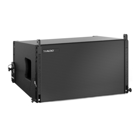
The main-cradle-frame MCT24 is an accessory for the T24(N) loudspeaker.
It is characterized by a subtle look, a remarkable size to weight ratio and ease of use.
Instructions in this user manual
NOTE
TIP
CAUTION
WARNING
Thank you for choosing a high-quality product “MADE IN GERMANY” from the brand
TW AUDiO.
If you lend your product to another party, inform that party of the safety-related operating pro-
cedures and hand over this assembly guide. If you require additional copies of this manual,
you can obtain them free of charge from TWAUDiO or download them from www.twaudio.de
Strictly adhere to the instructions contained in this operating manual that are marked as
follows:
This symbol in combination with the signal word “Warning” identifies a potentially hazardous
situation. Failure to comply with this safety instruction can lead to serious injury or even death.
This symbol in combination with the signal word “Caution” identifies a potentially hazardous
situation. Failure to comply with this safety instruction can lead to light or moderate injury.
This symbol in combination with the signal word “Note” identifies a potentially hazardous
situation. Failure to comply with this safety instruction can lead to product damage.
This symbol in combination with the signal word “Tip” identifies additional information or
notes that will simplify working with TWAUDiO products on the basis of practical experience.

Assembly Instructions MCT24
3
Notes on the products
Read manual
before use!
Before using the device, carefully read the assembly instructions and keep it with the
MCT24 main-cradle-frame.
General information
Assembly instructions: OM-MCT24
Version 2.0 en, 09/2022
© by TWAMBO 2022; all rights reserved.
All information contained in this operating manual was correct to the best of our knowledge
at the time of printing.
Quality warranties or assurance of suitability for a certain type of use based on the technical
specifications, dimensions and weights are not granted by TWAMBO.
TWAMBO also shall not assume liability for any secondary damage (property damage and/or
personal injury) nor for the failure to comply with this operating manual!
TWAMBO reserves the right to update this document based on recent developments.
TWAMBO GmbH
Karl-Hofer-Str. 42
14163 Berlin
Germany
Phone : + 49 (0) 71 41-48 89 89 0
Fax: + 49 (0) 71 41-48 89 89 99
WWW: www.twaudio.de

Assembly Instructions MCT24
4
Content
1. Safety | Intended use...................................................................................................... 5
2. Overview ........................................................................................................................ 7
2.1 Components ........................................................................................................... 7
3. Technical data ................................................................................................................ 8
3.1 Data sheet............................................................................................................... 8
4. Commissioning............................................................................................................... 9
4.1 Setup ...................................................................................................................... 9
4.2 Wind load ................................................................................................................ 9
4.3 General safety instructions for setting up the following rigging variants:.................. 10
4.4 Mounting ASK44 sling chain at one MCT24 main-cradle-frame ............................. 11
4.5 Mounting sequence with one MCT24 main-cradle-frame....................................... 12
4.6 Standard and maximal variant with one MCT24 main-cradle-frame ....................... 13
4.7 Mounting of two MCT24 main-cradle-frame .......................................................... 14
4.8 Mounting ASK44 sling chain on two MCT24 main-cradle-frames........................... 15
4.9 Mounting BAT24 adapter to two MCT24 main-cradle-frames ................................ 16
4.10 Standard and Maximum variant with two MCT24 main-cradle-frames ................. 17
5. Transport and storage .................................................................................................. 18
6. CE Conformity Declaration............................................................................................ 19
7. Disposal ....................................................................................................................... 19

Assembly Instructions MCT24
5
1. Safety | Intended use
The MCT24 main-cradle-frame was developed for use in professional sound systems. The
main-cradle-frame may only be used by trained and qualified personnel.
The MCT24 main-cradle-frame may only used with the T24(N) loudspeaker.
This rigging manual describes how to use the MCT24 main-cradle-frame correctly. Any other
use shall be deemed improper and may result in damage or even injury.
Modifications or alterations to individual parts of the MCT24 main-cradle-frame are not per-
mitted! Danger to life!
WARNING
Before every operation, check the scope of delivery of the MCT24 main-cradle-frame for its
completeness and ensure that all parts are in perfect condition.
The scope of delivery includes specified components. Only use the recommended and cer-
tified components.
WARNING
The MCT24 main-cradle-frame is designed both for indoor and outdoor use.
CAUTION
The MCT24 main-cradle-frame may only be used by trained and qualified personnel.
Personnel must check the MCT24 main-cradle-frame for suitability before each use.
WARNING
The MCT24 main-cradle-frame must be taken out of operation immediately as soon as visible
damage to the parts can be seen.
WARNING
Please keep all elements of the MCT24 main-cradle-frame away from children! The small
parts can easily be swallowed and lead to suffocation!
WARNING
Please adhere to the following safety instructions to avoid risks when using accessories.
Note the operating modes described in this assembly instructions. Other uses are not per-
missible.
Damage caused by improper use is not covered by TWAMBO.

Assembly Instructions MCT24
6
ThepayloadoftheMCT24 main-cradle-frameisdesigned ofnotmorethan 12x T24(N) loudspe-
aker. The following additional components are required for this: CBT24 cradle bar for flying,
BAT24 adapter, BBT24 bracket and BLT24 Boxlink connecting cables on both sides of the
T24(N) loudspeaker. Do not exceed this payload.
WARNING
When moving (assembling, dismantling, maintaining) the MCT24 main-cradle-frame with
T24(N) loudspeaker, ensure sufficient space to prevent collisions with other objects.
WARNING
Do not squeeze or twist the electrical cables of the T24(N) loudspeaker during the installation
of the MCT24 main-cradle-frame! The respective national electrotechnical rules and regula-
tions are applicable.
CAUTION
Before mounting the MCT24 main-cradle-frame check that e.g. ceilings are capable to
carrying the payload of the components.
WARNING
WARNING
WARNING
Make sure that no water pipes, electrical lines or any other lines are behind the intended place
of mounting.
Only use wall plugs and screws which are suitable for the intended mounting and structural
fabric. All screws must be set and tightened properly. Ensure that the fixing holes have the
correct depth and diameter. Always use all fixing holes.
Check the Double Stud connections each time you install the MCT24 main-cradle-frame.
They must be firmly engaged and secured with a safety locking splint. If this is no longer pos-
sible, the Double Stud connections with the safety locking splints must be replaced.
When working with heavy loads exceeding 20 kg (44 lbs.), use suitable aids (dollies, hoisting
slings, etc.). Multiple persons may be required depending on the situation.
NOTE
WARNING
WARNING
ThepayloadoftheMCT24 main-cradle-frameisdesignedofnot morethannineT24(N) loudspe-
akers when using two MCT24 main-cradle-frames bolted together as a T24(N) system clus-
ter. The following additional components are required for this: CBT24 cradle bar for flying,
BAT24 adapter, BBT24 bracket and BLT24 Boxlink connecting cables on both sides of the
T24(N) loudspeaker. Do not exceed this payload.

Assembly Instructions MCT24
7
2. Overview
2.1 Components
1. Hexagon screw M12 x 40................................................................................ 2 pieces
2. Hexagon nut with clamping part M12 .............................................................. 2 pieces
3. Main-cradle-frame .............................................................................................1 piece
Figure 2.1 - Overview
12
3

Assembly Instructions MCT24
8
3. Technical data
3.1 Data sheet
Standard variant:
Maximum load capacity:
in combination with:
2x CBT24 cradle bar for flying
2x BAT24 adapter,
4x BBT24 bracket and
4x BLT24 Boxlink-connecting cables
on both sides of the
T24(N) loudspeakers
4x T24(N)
Maximum variant:
Maximum load capacity:
in combination with:
2x CBT24 cradle bar for flying
2x BAT24 adapter,
12x BBT24 bracket and
20x BLT24 Boxlink-connecting cab-
les on both sides of the
T24(N) loudspeakers
12x T24(N)
Stardard variant with 2x MCT24
Maximum load capacity:
in combination with:
3x CBT24 cradle bar for flying
3x BAT24 adapter,
6x BBT24 bracket and
6x BLT24 Boxlink-connecting cables
on both sides of the
T24(N) loudspeakers
6x T24(N)
Maximum variant with 2x MCT24
Maximum load capacity:
in combination with:
3x CBT24 cradle bar for flying
3x BAT24 adapter,
9x BBT24 bracket and
12x BLT24 Boxlink-connecting cab-
les on both sides of the
T24(N) loudspeakers
9x T24(N)
Dimensions (h x w x d) 60 x 582 x 473 mm [2.36 x 22.91 x 18.62 in]
Weight 9,2 kg [20.28 lbs]
Surface Powder-coated

Assembly Instructions MCT24
9
4.1 Setup
The MCT24 main-cradle-frame is designed for hanging operation. TW AUDiO provides a wide
range of accessories to securely attach the main-cradle-frame.
NOTE
4. Commissioning
4.2 Wind load
WARNING
WARNING
TW AUDiO recommends using only the accessories specified by TWAUDiO for securing and
mounting loudspeakers.
Before setting up the system outdoors, consider unexpected wind conditions at the opera-
tion site!
Disassemble your system immediately when wind speeds exceed 8 bft (34 to 40 kn / 62 to
74 kph / 38.5 to 46 mph) and secure the system components!
Make sure that there are no persons in the immediate vicinity of the system structure!
Make sure that the system structures are not operated over the audience at wind speeds in
excess of 6 bft (22 to 27kn / 39 to 49kph / 24.2 to 30.45mph) and that there are no persons
in the immediate vicinity of the system structure!
Please note that setting up the MCT24 main-cradle-frame always requires two persons!
WARNING

Assembly Instructions MCT24
10
Attach this secondary safety component by using one furthermore shackle, chain sling or
chain hoist on another pin point.
WARNING
WARNING
NOTE
WARNING
WARNING
4.3 General safety instructions for setting up the following rigging variants:
Any influences on your system setup, such as leaning against objects (or people) and flying
objects around, be refrained from!
Attach the ASK sling chain to four other pin points on the MCT24 main-cradle-frame for each
system setup. Use a sling chain or chain hoist to hang the ASK sling chain with the system
setup.
Use shackles that are designed according to the payload for each system setup.
For the secondary safety component, the respective national electrotechnical regulations apply.

Assembly Instructions MCT24
11
4.4 Mounting ASK44 sling chain at one MCT24 main-cradle-frame
WARNING
WARNING
Figure 4.4 - Mounting ASK44 sling chain at one MCT24 main-cradle-frame
Note that for the MCT24 main-cradle-frame you cannot determine the number of
T24(N) loudspeakers which matching your application as well as the appropriate pin points
using the EASE Focus simulation software!
Then attach the ASK44 sling chain with the shackles to four another pin points on the
MCT24 main-cradle-frame, as shown for example in Figure 4.4.
Make sure that the MCT24 main-cradle-frame is held in the horizontal position with the
ASK44 sling chain in every application with your system setup!
Determine always the pin points you require before setting up the system!
NOTE

Assembly Instructions MCT24
12
4.5 Mounting sequence with one MCT24 main-cradle-frame
Be sure to follow the assembly sequence below to mount the T24(N) loudspeakers to the
MCT24 main-cradle-frame via the CBT24 cradle bar for flying:
Figure 4.5 - Mounting T24(N) to MCT24 with CBT24 and BAT24
1. Attach the shackle of the CBT24 cradle bar for flying to another pin point with another
shackle designed according to the total weight.
2. Before mounting the BAT24 adapter, observe its assembly and safety instructions!
3. Before mounting the BBT24 bracket, observe its assembly and safety instructions!
4. Now connect the BBT24 bracket with the BAT24 adapter via the upper quick-locking pin
of the BBT24 bracket!
4.
1.
4.
BBT24
Grafic shown without ASK44 sling chain.
WARNING
WARNING
WARNING
Check that all quick-locking pins are always completely inserted!
Check that all Double Studs are engaged and that they have been secured with safety locking
splints!

Assembly Instructions MCT24
13
4.6 Standard and maximal variant with one MCT24 main-cradle-frame
NOTE
WARNING
Connect a maximum of 12x T24(N) loudspeakers to each other using the BBT24 brackets
(12 pieces) and the BLT24 Boxlink connector cables (20 pieces). The BLT24 Boxlink connec-
tor cables on both sides of the T24(N) loudspeakers.
Figure 4.6 - Standard variant
The standard variant has established itself in which four T24(N) loudspeakers are used
with two CBT24 cradle bar for flying, four BBT24 brackets, two BAT24 adapter and four
BLT24 Boxlink connector cables. (See figure 4.6)
T24(N)
T24(N) BBT24
BBT24
BAT24
CBT24
4x BLT24
Grafic shown without ASK44 sling chain.

Assembly Instructions MCT24
14
4.7 Mounting of two MCT24 main-cradle-frame
WARNING
Screw the two MCT24 main-cradle-frames to the side beams as shown for example in
figure 4.7. For this purpose, use the hexagon screws and nuts included in the scope of deli-
very.
For applications where the T24(N) system cluster needs to be extended laterally, two
MCT24 main-cradle-frames can be bolted together at the side beams.
Before screwing the two MCT24 main-cradle-frames together, always note the pin points
that match your application. Also note that your system setup is held in the horizontal position
with the ASK44 sling chain!
Determine always the pin points you require before setting up the system!
Only then screw the two MCT24 main-cradle-frames together!
Figure 4.7 - Bolting two MCT24 main-cradle-frames together
WARNING

Assembly Instructions MCT24
15
WARNING
WARNING
4.8 Mounting ASK44 sling chain on two MCT24 main-cradle-frames
Figure 4.8 - Mounting ASK44 sling chain at two MCT24 main-cradle-frames
NOTE
Note that for the MCT24 main-cradle-frame you cannot determine the number of
T24(N) loudspeakers which matching your application as well as the appropriate pin points
using the EASE Focus simulation software!
Then attach the ASK44 sling chain with the shackles to four another pin points on the center
supports of the two MCT24 main-cradle-frames, as shown for example in figure 4.8.
Make sure that the two MCT24 main-cradle-frames are held in the horizontal position with the
ASK44 sling chain in every application with your system setup!
Determine always the pin points you require before setting up the system!

Assembly Instructions MCT24
16
4.9 Mounting BAT24 adapter to two MCT24 main-cradle-frames
WARNING
WARNING
WARNING
WARNING
Figure 4.9 - Mounting of three BAT24 at two MCT24
Grafic shown without ASK44 sling chain.
Attach the three BAT24 adapters to two pin points on each of the side beams of the two
MCT24 main-cradle-frames, as shown for example in figure 4.9.
Use the two lower holes of the BAT24 adapter for this purpose!
For applications where the T24(N) system cluster has been extended laterally, three
CBT24 system setups, each with two T24(N) loudspeakers, can now be attached to the two
MCT24 main-cradle-frames.
Note that the distance plate of the middle BAT24 adapter is not used! (see assembly instruc-
tions BAT24 - page 7 - chapter 2.1 - pos.1)
Be sure to follow the mounting sequence of chapter 4.5 on page 12 to mount the
T24(N) loudspeakers to the MCT24 main-cradle-frame via the CBT24 cradle bar for flying.
upper
holes
lower
holes
WARNING
Check that all quick-locking pins are always completely inserted!
Check that all Double Studs are engaged and that they have been secured with safety locking
splints!

Assembly Instructions MCT24
17
Connect a maximum of nine T24(N) loudspeakers to each other using the BBT24 brackets
(9 pieces) and the BLT24 Boxlink connector cables (12 pieces). The BLT24 Boxlink connec-
tor cables on both sides of the T24(N) loudspeakers.
WARNING
The standard variant has established itself in which six T24(N) loudspeakers are used
with three CBT24 cradle bar for flying, six BBT24 brackets, three BAT24 adapter and six
BLT24 Boxlink connector cables. (See figure 4.10)
NOTE
Figure 4.10 - Standard variant
4.10 Standard and Maximum variant with two MCT24 main-cradle-frames
Grafic shown without ASK44 sling chain.
T24(N)
T24(N)
BBT24
BBT24
BAT24
CBT24
6x BLT24

Assembly Instructions MCT24
18
NOTE
5. Transport and storage
Ensure that the surface of the Main-cradle-frame is not damaged during transport and sto-
rage. Moisture may penetrate where steel surfaces are exposed by scratches and result in
corrosion.
This is why the product should be transported in a safe, careful, dry and largely dust-free
manner.
The following accessory parts for the Main-cradle-frame are available from TW AUDiO:
• Shackle SK10
• Hexagon screw M12 x 40
• Hexagon nut with clamping part M12
The original packaging is unsuitable as permanent storage and transport packaging.

Assembly Instructions MCT24
19
as well as all model variants based on these, provided that they correspond to the original
factory models and have not been technically modified in any way.
Applicable directives:
• 2001/95/EG
Applicable national standards and technical specifications:
• DIN EN 18 800
• DIN EN ISO 12 100
• DGUV Vorschrift 17 und 18
Berlin, Germany, January 1st, 2021
Bernhard Wüstner
7. Disposal
Diese Erklärung betrifft folgende Komponenten
• MCT24
6. CE Conformity Declaration
If you have any question regarding the disposal of used devices, please contact us under the
following telephone number:
+49 (0) 71 41 - 48 89 89 0
In countries outside of the European Union, comply with local regulations.
Copy and translation of the original CE Conformity Declaration:
We hereby declare that the below-referenced components by virtue of their design and con-
struction, and in the configuration placed on the market by us, satisfy the safety and health
requirements of the applicable EC directives. This declaration becomes invalid in case of modi-
fications that have not been approved by us.

Assembly Instructions MCT24
20
TWAMBO GmbH
Karl-Hofer-Str. 42
14163 Berlin
Germany
Phone: + 49 (0) 71 41-48 89 89 0
Fax: + 49 (0) 71 41-48 89 89 99
WWW: www.twaudio.de
Table of contents
Other TW Audio Speakers manuals

TW Audio
TW Audio M8 User manual

TW Audio
TW Audio B10i User manual

TW Audio
TW Audio VERA20 User manual

TW Audio
TW Audio B15 User manual

TW Audio
TW Audio T20 User manual

TW Audio
TW Audio M15 User manual

TW Audio
TW Audio BAT24 User manual

TW Audio
TW Audio T24 Quick start guide

TW Audio
TW Audio URA30i User manual

TW Audio
TW Audio B17i User manual

TW Audio
TW Audio T24N User manual

TW Audio
TW Audio ARBT24 User manual

TW Audio
TW Audio C12 User manual

TW Audio
TW Audio FDBSX User manual

TW Audio
TW Audio VERA20 User manual

TW Audio
TW Audio M10 User manual

TW Audio
TW Audio C15 User manual

TW Audio
TW Audio B18 User manual

TW Audio
TW Audio B15 User manual

TW Audio
TW Audio VERA36 Series User manual