TW Audio B10 User manual

Operation manual
B10

Operation manual B10
2
Introduction
A sudden impact in depth paired with an exactly defined sound – this is what “bass” sounds
like.
The dimensions of our “smallest” let not assume such a performance. But the B10 wouldn’t
be a TW AUDiO sub if it hadn’t more to offer: Its newly developed long excursion cone driver
with an uncompromising 3“ dual voice coil and optional passive cross-over with switcha-
ble high-pass outputs enable the standard bi-amp mode amongst numerous other passive
applications:
One single B10 in stereo mode together with two C5 tops, two B10 switched to mono each
with one M8, or four B10 together with two M10, all variations powered by one standard
amplifier.
Instructions in this user manual
NOTE
CAUTION
WARNING
WARNING
Thank you for choosing a high-quality product “MADE IN GERMANY” from the brand
TW AUDiO.
If you lend your product to another party, inform that party of the safety-related operating pro-
cedures and hand over this assembly guide. If you require additional copies of this manual,
you can obtain them free of charge from TWAUDiO or download them from www.twaudio.de
Strictly adhere to the instructions contained in this operating manual that are marked as
follows:
This symbol in combination with the signal word “Warning” identifies a potentially hazardous
situation. Failure to comply with this safety instruction can lead to serious injury or even death.
This symbol in combination with the signal word “Warning” identifies a potentially hazardous
situation for persons with a pacemaker. Failure to comply with this safety instruction can lead
to serious injury or even death.
This symbol in combination with the signal word “Caution” identifies a potentially hazardous
situation. Failure to comply with this safety instruction can lead to light or moderate injury.
This symbol in combination with the signal word “Note” identifies a potentially hazardous
situation. Failure to comply with this safety instruction can lead to product damage.

Operation manual B10
3
TIP
Notes on the products
Read manual
before use! Before using the device, carefully read the operating manual and keep it with the B10 loudspe-
aker.
General information
Operation manual: OM-B10
Version 2.0 en, 01/2022
This symbol in combination with the signal word “Tip” identifies additional information or
notes that will simplify working with TWAUDiO products on the basis of practical experience.
© by TWAMBO 2022; all rights reserved.
All information contained in this operating manual was correct to the best of our knowledge
at the time of printing.
Quality warranties or assurance of suitability for a certain type of use based on the technical
specifications, dimensions and weights are not granted by TWAMBO.
TWAMBO also shall not assume liability for any secondary damage (property damage and/or
personal injury) nor for the failure to comply with this operating manual!
TWAMBO reserves the right to update this document based on recent developments.
TWAMBO GmbH
Karl-Hofer-Str. 42
14163 Berlin
Germany
Phone : + 49 (0) 71 41-48 89 89 0
Fax: + 49 (0) 71 41-48 89 89 99
WWW: www.twaudio.de

Operation manual B10
4
Content
1. Safety | Intended use...................................................................................................... 5
2. Overview ........................................................................................................................ 7
2.1 Components ........................................................................................................... 7
2.2 Variants ................................................................................................................... 8
2.2.1 B10A / B10P model ........................................................................................... 8
2.3 Operation modes..................................................................................................... 9
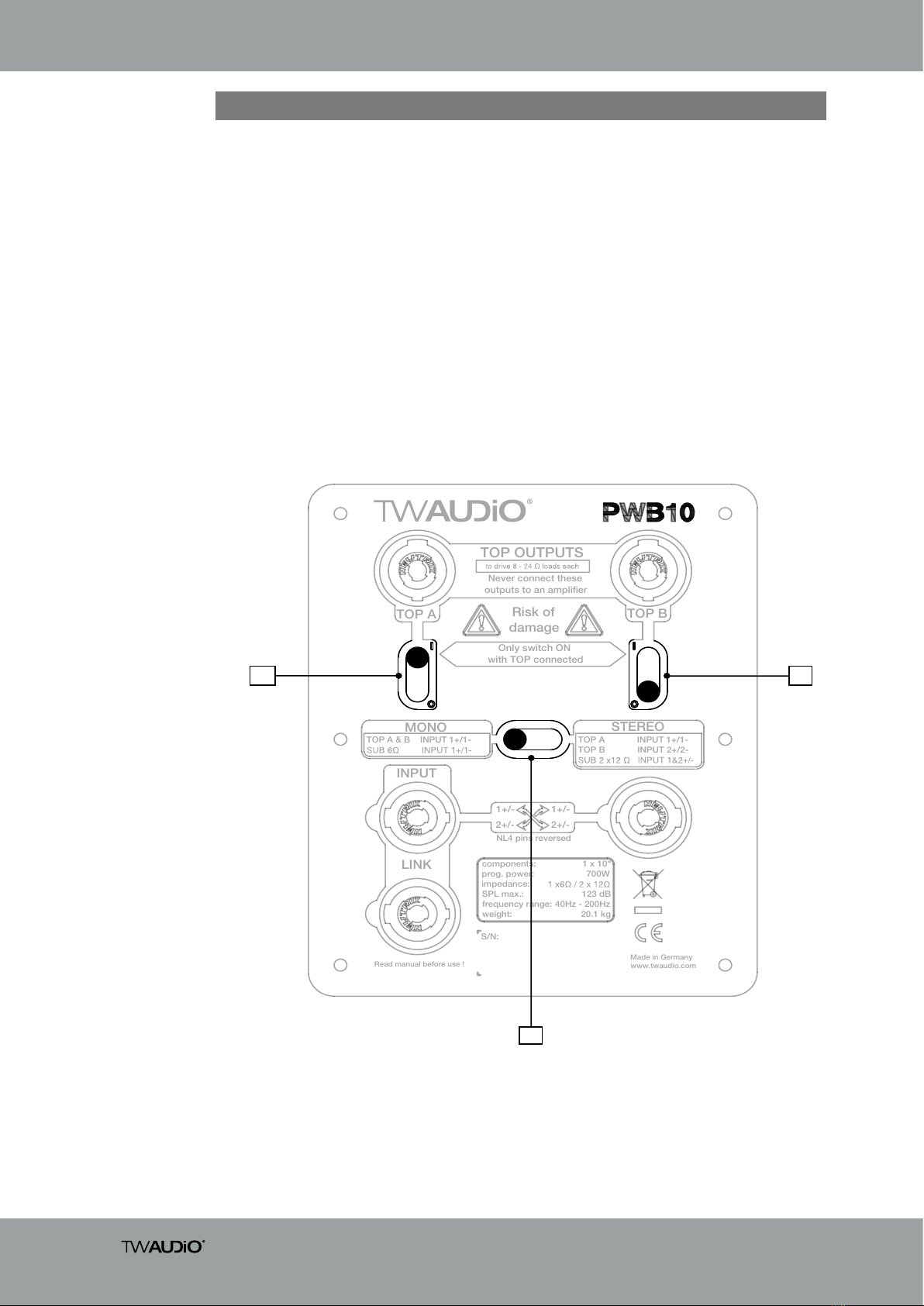
2.3.1 Selector switch S3 - MONO/STEREO mode ...................................................... 9
2.3.2 Selector switch S1 and S2 - TOP OUTPUT mode ............................................ 10
3. Technical data .............................................................................................................. 11
3.1 Data sheet............................................................................................................. 11
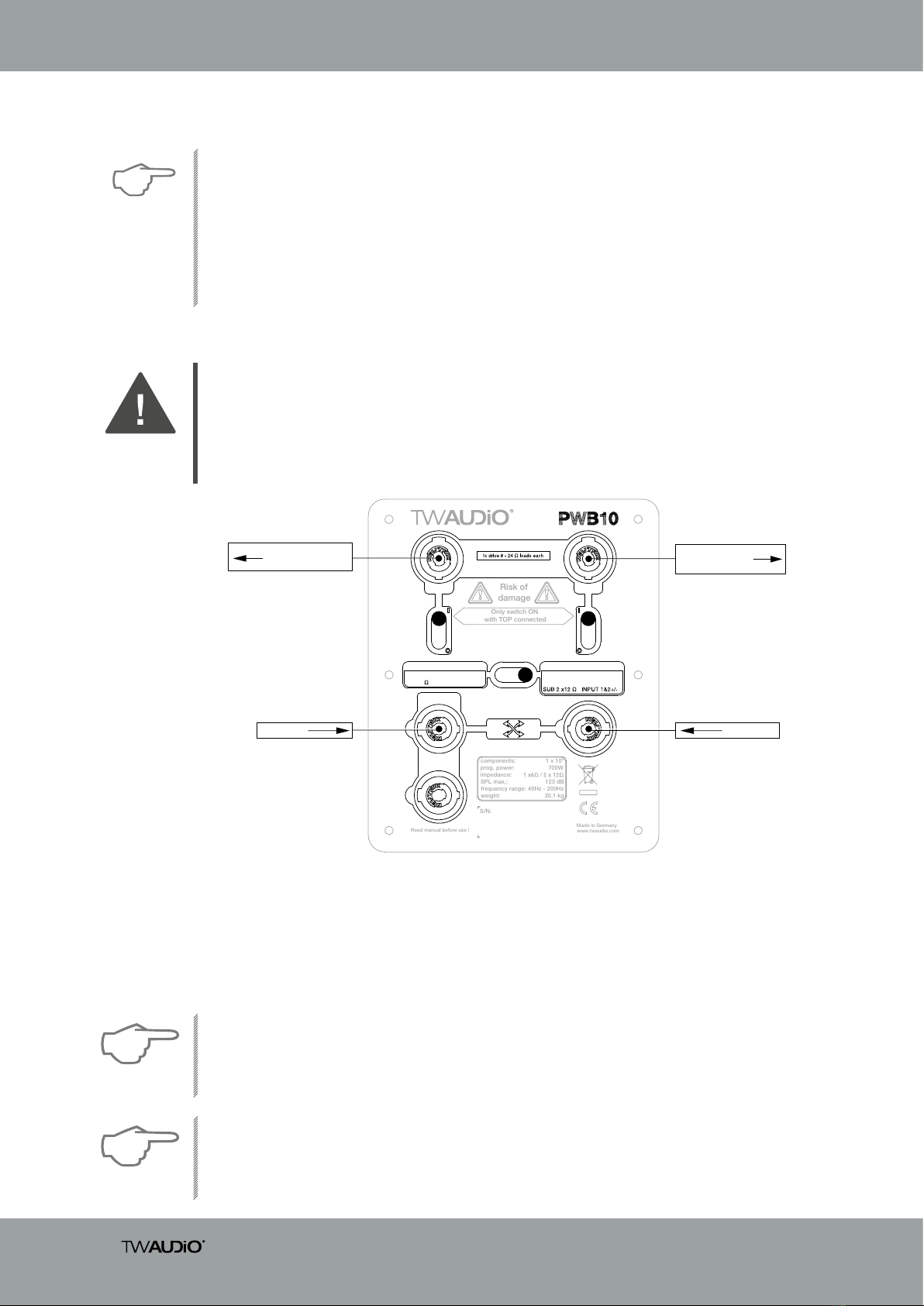
3.2 Connection diagram .............................................................................................. 11
3.2.1 Variant: B10A ................................................................................................... 11
3.2.2 Variant: B10P ................................................................................................... 12
4. Commissioning............................................................................................................. 13
4.1 Setup .................................................................................................................... 13
4.2 M20 pole mount flange.......................................................................................... 13
4.3 Operation .............................................................................................................. 16
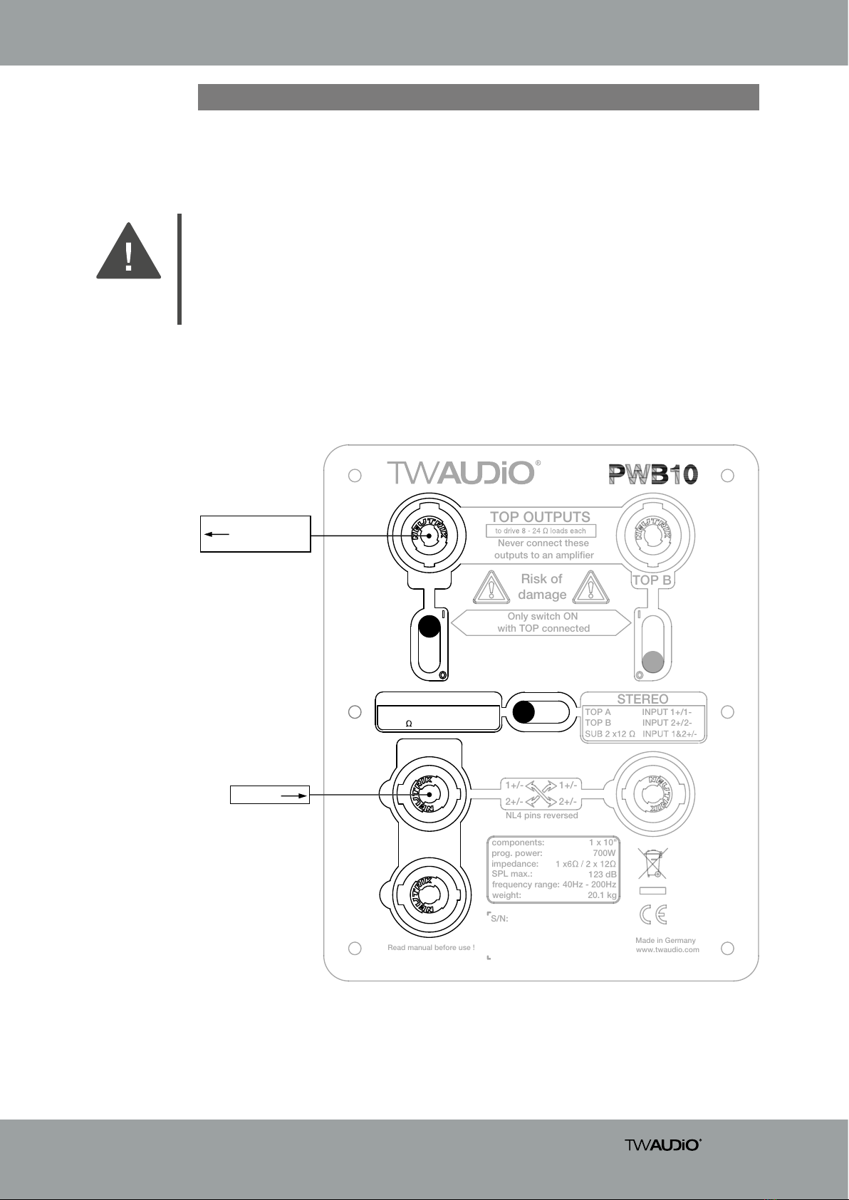
4.4 Connecting the cable............................................................................................. 16
5. Transport and storage .................................................................................................. 17
6. CE Conformity Declaration............................................................................................ 18
7. Disposal ....................................................................................................................... 19

Operation manual B10
5
1. Safety | Intended use
The B10 loudspeaker was developed for use in professional sound systems. The loudspea-
ker may only be used by trained and qualified personnel.
WARNING
WARNING
WARNING
NOTE
NOTE
Avoid:
• Feedback
• Distorted signals (clipping) and
• Peaks resulting from switching on devices, plugging in devices or unplugging devices during
operation.
Such signals can lead to loudspeaker overload and ultimately to loudspeaker failure.
Keep away from the immediate vicinity of loudspeakers that are operated at high sound pres-
sure levels. These loudspeaker systems are capable of endangering your health. Sound levels
beginning as low as approximately 90dBSPL can lead to long-term hearing impairment.
When setting up loudspeakers, ensure that they are not exposed to the following ambient
conditions:
• Direct sunlight
• Humidity
• Jolting
• Dust
When working with heavy loads exceeding 20 kg (44 lbs.), use suitable aids (dollies, hoisting
slings, etc.). Multiple persons may be required depending on the situation.
Ensure that the units are in a stable position and are firmly attached. A falling loudspeaker can
result in serious personal injury and property damage.
When using and assembling TW AUDiO loudspeakers, only use materials specified by
TW AUDiO. These tasks must be performed by qualified personnel. Adhere to the applicable
safety regulations.
Loudspeakers generate an electromagnetic field. Persons with pacemakers are not permit-
ted to remain in the immediate vicinity of loudspeakers as the electromagnetic fields can
cause pacemakers to malfunction.
Please adhere to the following safety instructions to avoid risks when operating loudspeakers.
Note the operating modes described in this operating manual. Other uses are not permis-
sible.
Damage caused by improper use is not covered by TWAMBO.

Operation manual B10
6
WARNING
NOTE
NOTE
Ensure that the loudspeaker is not exposed to permanent thermal overloads. Thermal over-
loads may cause a fire and result in serious personal injury and property damage.
Note that TWAMBO does not provide a warranty for damage that can be attributed to this type
of overload and therefore cannot be held liable for any secondary damage.
A permanent magnetic field is present in the immediate vicinity of loudspeakers. Ensure that
objects which react sensitively to magnetic fields are not located in the immediate vicinity of
the loudspeaker. In particular, this applies to magnetic storage media, magnetic stripe cards
such as debit cards and CRT displays. A distance of approximately one meter is sufficient to
avoid damage.
Check loudspeakers and accessory parts regularly for visible wear. This is essential to ensure
continuing fault-free operation. Worn parts should be replaced immediately. Spare parts are
available from TWAUDiO.

Operation manual B10
7
2. Overview
2.1 Components
1. 10“ cone driver
2. 15 mm multiplex housing – Warnex texture paint surface finish
3. M20 pole mount flange for attaching a distance rod
4. Milling for rubber feet for safely stacking loudspeakers
5. Ergonomic carrying handle (top and bottom)
6. Standard connection panel
7. Type label
8. PWB10 passive crossover
9. Rubber feet (8 pieces)
Figure 2.1 - Overview
15
9
67
3 4
2
8
B10 active B10 passive

Operation manual B10
8
2.2 Variants
The B10 loudspeaker comes in two different variants. The distinction is between the B10A
(ACTIVE model) and B10P (PASSIVE model).
Read manual before use !
Made in Germany
www.twaudio.com
NL4 pins reversed
S/N:
Never connect these
outputs to an amplifier
TOP A & B INPUT 1+/1-
TOP A INPUT 1+/1-
TOP B INPUT 2+/2-
MONO
INPUT
STEREO
LINK
TOP A
TOP B
TOP OUTPUTS
Risk of
damage
Only switch ON
with TOP connected
1+/-
2+/-
1+/-
2+/-
components:
prog. power:
impedance:
SPL max.:
frequency range:
weight:
1 x 10"
700W
123 dB
40Hz - 200Hz
20.1 kg
S1
S3
S2
Figure 2.2 - Overview selector switches
The standard version of the B10 loudspeaker is the B10A variant which can only be operated
in „ACTIVE“ mode. It comes with a standard connection panel. The separation takes place in
the amplifier DSP.
The B10P version can be used either passively (using the “MONO” and “STEREO” operating
modes) or active with the corresponding preset.
The integrated passive crossover (item 8 “Figure 2.1 - Overview” on page 7.) has three selector
switches that are described in the following chapter.
2.2.1 B10A / B10P model

Operation manual B10
9
2.3 Operation modes
2.3.1 Selector switch S3 - MONO/STEREO mode
1. Connect the top loudspeaker to the high pass output (TOP A)!
Never connect an amplifier to this connector!
2. Switch the switch S3 to „MONO“.
3. Switch the switch S1 to „ON“.
WARNING
Figure 2.3.1.1 - Overview operation MONO
Read manual before use !
Made in Germany
www.twaudio.com
NL4 pins reversed
S/N:
Never connect these
outputs to an amplifier
TOP A & B INPUT 1+/1-
SUB 6 INPUT 1+/1-
TOP A INPUT 1+/1-
TOP B INPUT 2+/2-
MONO
INPUT
STEREO
LINK
TOP A
TOP B
TOP OUTPUTS
Risk of
damage
Only switch ON
with TOP connected
1+/-
2+/-
1+/-
2+/-
components:
prog. power:
impedance:
SPL max.:
frequency range:
weight:
1 x 10"
700W
123 dB
40Hz - 200Hz
20.1 kg
INPUT
OUTPUT to
speaker
One input channel is required for operation in „MONO“ mode.

Operation manual B10
10
Figure 2.3.1.2 - Overview
Two input channels are required for operation in „STEREO“ mode. The left input is assigned to
pin 1+/-, the right input to pin 2+/-.
1. Connect the top loudspeakers to the “high pass outputs” (TOP A and TOP B)!
Never connect amplifiers to these connectors!
2. Switch the switch S3 to „STEREO“.
3. Switch the switches S1 and S2 to „ON“.
WARNING
Never change the operation mode while the loudspeaker is in operation. This may damage the
connected loudspeakers.
Operation mode 1 „ACTIVE“ additionally requires the correct preset at the amplifier.
NOTE
Note that the total impedance may vary depending on the connected loudspeaker. See
“Connecting the cable” on page 16.
NOTE
2.3.2 Selector switch S1 and S2 - TOP OUTPUT mode
Read manual before use !
Made in Germany
www.twaudio.com
NL4 pins reversed
S/N:
Never connect these
outputs to an amplifier
TOP A & B INPUT 1+/1-
SUB 6 INPUT 1+/1-
TOP A INPUT 1+/1-
TOP B INPUT 2+/2-
MONO
INPUT
STEREO
LINK
TOP A TOP B
TOP OUTPUTS
Risk of
damage
Only switch ON
with TOP connected
1+/-
2+/-
1+/-
2+/-
components:
prog. power:
impedance:
SPL max.:
frequency range:
weight:
1 x 10"
700W
123 dB
40Hz - 200Hz
20.1 kg
OUTPUT to
speaker B
INPUT Reversed
OUTPUT to
speaker A
HINWEIS
If only single-channel cables (PIN 1+/-) are used, connect the left channel’s cable to the “Input”
connector. Connect the right channel’s cable to the “Reversed” connector.
If a four-pin cable is used for both channels (L = 1+/-, R = 2+/-), connect this cable to the
“Input” connector.
Never connect two amplifier channels to the “Input” and “Reversed” connectors using two
four-pin cables at the same time, as this may short-circuited and damage the amplifier.
The two vertical selector switches (see figure 3.2.3 - S1 and S2) activate the respective
high pass output. This makes it possible to connect and operate a mid/high range loudspe-
aker with a rated passive crossover of between 8 - 24Ohms on the TOP OUTPUT outputs.

Operation manual B10
11
3.1 Data sheet
3. Technical data
Variant
B10A B10P
Drivers 1x 10“ LF
Frequency
response 40 - 400Hz 40 - 200 Hz
Power handling
(program/Peak) 700 / 1400W 700 / 1400 W
Impedance 1x 8 Ω
(optional 2x 16 Ω)
1x 6 Ω or 2x 12 Ω
switchable
Max. SPL / 1 m 123 dB
Dimensions
(h x w x d) 304 x 504 x 440 mm [12,0 x 19,8 x 17,3 in]
Weight 16,1 kg [35,5 lbs] 20,1 kg [44,3 lbs]
Surface Warnex textured paint
3.2 Connection diagram
3.2.1 Variant: B10A
Figure 3.2.1 - Connection diagram B10A
8 OHM
PIN 1+
PIN 1-
PIN 2+
PIN 2-
PIN 1+
PIN 1-
PIN 2+
PIN 2-
parallel
10"
+
-

Operation manual B10
12
Figure 3.2.2.1 - Connection diagram B10P - MONO
3.2.2 Variant: B10P
-
TOP A ON
dual-coil
10"
+
+
-
PIN 1-
PIN 1+
PIN 2-
PIN 2+
TOP A
LPF
LPF
HPF
MONO MODE
TOP B OFF
HPF
S1
S3 S2
PIN 1-
PIN 1+
PIN 2-
PIN 2+
PIN 1-
PIN 1+
PIN 2-
PIN 2+
REVERSED
LINK
INPUT
Figure 3.2.2.2 - Connection diagram B10P - STEREO
TOP B
-
TOP A ON
dual-coil
10"
+
+
-
PIN 1-
PIN 1+
PIN 2-
PIN 2+
TOP A
LPF
LPF
HPF
MONO MODE
TOP B OFF
HPF
S1
S3
S2
PIN 1-
PIN 1+
PIN 2-
PIN 2+
PIN 1-
PIN 1+
PIN 2-
PIN 2+ REVERSED
LINK
INPUT

Operation manual B10
13
4.1 Setup
The B10 loudspeaker is designed for standing operation.
NOTE
WARNING
4. Commissioning
4.2 M20 pole mount flange
WARNING
WARNING
WARNING
WARNING
The M20 pole mount flange (figure 2.1- item 2) is not designed for side forces once mounted
– do not apply any pressure from the sides.
Make sure that no external forces are applied to the system structures. No objects or persons
should lean against the structures, no objects should be thrown against them. If pressure is
applied on the flange the loudspeaker may be damaged or falling over.
Make sure that no unauthorized persons can access the system structures!
Cordon off the area professionally!
Make sure that the maximum load of 50kg / 110lbs for the M20 pole mount flange is not
exceeded! Figure 2.1 – Item 2.
For all system components mounted on top of the M20 pole mount flange, observe the res-
pective operating instructions!
Also be sure to observe all of the following warnings:
TW AUDiO recommends using only the accessories specified by TWAUDiO for securing and
mounting loudspeakers.
Make sure the speakers are securely fastened to prevent personal injury and property damage.
Secure stacked loudspeakers properly so that they can be tipped by 10° in any direction
without toppling.
Make sure that all system structures are located on a firm, level surface and that the surface
can bear the total weight!

Operation manual B10
14
WARNING
Figure 4.2.1 - system setup B10
WARNING
WARNING
Please note that only centered loads are allowed to be placed on the M20 pole mount flange
– Figure 2.1 – Item 2.
Make sure that the system structures are not operated over the audience at wind speeds in
excess of 6 bft (22 to 27kn / 39 to 49kph / 24.2 to 30.45mph) and that there are no persons
in the immediate vicinity of the system structure!
Before setting up the system outdoors, consider unexpected wind conditions at the opera-
tion site!
Disassemble your system immediately when wind speeds exceed 8 bft (34 to 40 kn / 62 to
74 kph / 38.5 to 46 mph) and secure the system components!
Make sure that there are no persons in the immediate vicinity of the system structure!

Operation manual B10
15
Figure 4.2.2 - B10 – improper installation
Figure 4.2.3 - B10 – improper wall mounting

Operation manual B10
16
4.3 Operation
Operation of the B10A speaker requires a DSP-Controller. TW AUDiO recommends opera-
ting the B10P loudspeaker on a DSP-Controller. For this purpose, only presets developed by
TW AUDiO are recommended. The TWAUDiO system racks are ideally suited for this purpose.
Please note the technical data in section 3.1 on page 11.
NOTE
NOTE
4.4 Connecting the cable
The pin connections of the B10 loudspeaker can be found in section 3.2 (“Connection dia-
gram”) on page 11 and 12.
The internal wiring of the B10 loudspeaker allows for parallel connection of multiple loudspe-
aker units.
NOTE
To create a cable connection with an amplifier rack from TWAUDiO, proceed as follows.
Ensure that the cable cross sectional area is sufficient (at least 1.5 mm²) to avoid power losses.
TW AUDiO recommends using the loudspeaker cables available from TWAUDiO.
When connecting the cables to the loudspeaker, ensure that polarity (+/-) and pin assignment
(1/2) are correct. Incorrect connection can lead to a significant change in the loudspeaker’s
sound characteristics and may damage the driver.
Please note that parallel connections will decrease the total impedance of your loudspeaker
configuration.
The total impedance and the resulting power of the speaker configuration must match the
output power of the amplifier.
Before connecting the loudspeaker to the amplifier, ensure that the right preset has been
loaded.
Using a wrong, out dated or a preset not provided by TWAUDiO can lead to destruction of
the speaker.
Make sure that the amplifier’s specifications meet the requirements. Using an amplifier that
doesn’t meet the specifications can destroy the loudspeaker.

Operation manual B10
17
To enable a single person to transport several multiple B10 loudspeakers, TW AUDiO recom-
mends using the QDB10 quad dolly.
NOTE
5. Transport and storage
Due to the B10 loudspeaker weighing over 20 kg [44.09 lbs.], two persons are required to
handle and transport the unit.
• QDB10 (Quaddolly)
• BagB10 (Carrying bag)
When transporting and storing the unit, it is important to ensure that the surface and front
grill of the loudspeaker are not damaged. Moisture can penetrate through exposed wood
surfaces and cause the wood to swell. A bent or broken front grill will no longer adequately
protect the sensitive speaker membranes.
In addition, appreciable dust deposits may considerably impair the functionality of a loudspe-
aker membrane. For this reason, the loudspeakers should be transported and stored in a
safe, careful, dry and largely dust-free manner.
The following accessory parts for transport and storage are available from TW AUDiO:
The original packaging is unsuitable as permanent storage and transport packaging.

Operation manual B10
18
as well as all model variants based on these, provided that they correspond to the original
factory models and have not been technically modified in any way.
Applicable directives:
• 2001/95/EG
• 2011/65/EU
Applicable national standards and technical specifications:
• DIN EN 18 800
• DIN EN ISO 12 100
• DGUV Vorschrift 17 und 18
• EN 50581: 2013-02
Berlin, Germany, January 1st, 2021
Bernhard Wüstner
This declaration applies to the following components
• B10A
• B10P
6. CE Conformity Declaration
Copy and translation of the original CE Conformity Declaration:
We hereby declare that the below-referenced components by virtue of their design and
construction, and in the configuration placed on the market by us, satisfy the safety and
health requirements of the applicable EC directives. This declaration becomes invalid in
case of modifications that have not been approved by us.

Operation manual B10
19
7. Disposal
It is prohibited to dispose of used electrical equipment with household refuse.
All TWAMBOGmbH products are so-called B2B-products. This means that they are sold by
a commercial business to a commercial business. TWAMBO products that bear the trash can
symbol shown here may only be disposed of by TWAMBO.
The loudspeaker owner is legally responsible for proper disposal of used devices that do not
bear this symbol. This pertains to all products delivered prior to March 29, 2010. Nevertheless,
TWAMBO will also be happy to assist you in this case.
If you have any question regarding the disposal of used devices, please contact us under the
following telephone number:
+49 (0) 71 41 - 48 89 89 0
Thus, TWAMBO is in strict compliance with the Waste Electrical and Electronic Equipment
Directive (2012/19/EU) for the protection of our environment.
TWAMBO is registered under the following WEEE-reg.-no. with the German National Register
EAR as a B2B-manufacturer and distributor of electrical devices:
DE93295191
In countries outside of the European Union, comply with local regulations.

Operation manual B10
20
TWAMBO GmbH
Karl-Hofer-Str. 42
14163 Berlin
Germany
Phone: + 49 (0) 71 41-48 89 89 0
Fax: + 49 (0) 71 41-48 89 89 99
WWW: www.twaudio.de
Table of contents
Other TW Audio Subwoofer manuals

TW Audio
TW Audio BSX User manual

TW Audio
TW Audio VERA S17i User manual

TW Audio
TW Audio B14i User manual

TW Audio
TW Audio i Series User manual

TW Audio
TW Audio BSX User manual

TW Audio
TW Audio VERAS30 User manual

TW Audio
TW Audio VERA S33 User manual

TW Audio
TW Audio T30i User manual

TW Audio
TW Audio B10A User manual

TW Audio
TW Audio B17i User manual