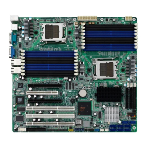
TYAN Thunder n4250QE-S4985G3NR-E User manual

1
Thundern4250QE
///
S4985G3NR-E
Version1.0
Copyright
Copyright TYANComputerCorporation,2006.All rightsreserved. Nopartof
thismanualmaybereproducedortranslatedwithout priorwrittenconsentfrom
TYANComputerCorp.
Trademark
Allregisteredandunregisteredtrademarksandcompanynamescontainedin
thismanualarepropertyoftheirrespectiveownersincluding, butnot limitedto
thefollowing.
TYAN, Thundern4250QEaretrademarksofTYANComputerCorporation.
AMD,Opteron,andcombinationsthereof aretrademarksofAMDCorporation.
Phoenix, Phoenix-AwardBIOSaretrademarksof PhoenixTechnologies.
Notice
InformationcontainedinthisdocumentisfurnishedbyTYANComputer
Corporationandhasbeenreviewedforaccuracyandreliabilitypriortoprinting.
TYANassumesnoliabilitywhatsoever,anddisclaimsanyexpress orimplied
warranty,relatingtosaleand/oruseofTYANproductsincluding liabilityor
warrantiesrelating tofitness foraparticularpurposeormerchantability. TYAN
retainstherighttomakechangestoproductdescriptionsand/orspecifications
at anytime,withoutnotice.Innoevent willTYANbeheldliableforanydirector
indirect,incidentalorconsequentialdamage,loss ofuse,lossofdataorother
maladyresultingfromerrorsorinaccuraciesofinformationcontainedinthis
document.

2
TableofContents
Check theboxcontents! 3
Chapter1:Introduction
1.1Congratulations……………………………………………………………
5
1.2HardwareSpecifications…………………………………………………
5
Chapter2:BoardInstallation
2.1 BoardImage………………………………………………………………
8
2.2 BlockDiagram…………………………………………………………….
9
2.3 BoardParts, JumpersandConnectors………………………………...
10
2.4 TipsonInstallingMotherboardinChassis……………………………..
20
2.5 InstallingtheProcessor(s)……………………………….......................
21
2.6 InstallingtheMemory…………………………………………………….
24
2.7 Attaching DriveCables…………………………………………………..
26
2.8 InstallingAdd-inCards………………………………............................
28
2.9 ConnectingExternalDevices……………………………………………
29
2.10 InstallingthePowerSupply……………………………………………...
30
2.11 Finishingup……………………………………………………………….
30
Chapter3:BIOSSetup
3.1 AbouttheBIOS……………………………………………………………
31
3.2 BIOSMainMenu………………………………………………………….
33
3.3 AdvancedMenu…………………………………………………………..
41
3.4 SecurityMenu……………………………………………………………..
54
3.5 PowerMenu……………………………………………………………….
55
3.6 Boot Menu…………………………………………………………………
56
3.7 Exit Menu………………………………………………………………….
57
Chapter4:Diagnostics
4.1 BeepCodes……………………………………………………………….
59
4.2 FlashUtility………………………………………………………………..
59
4.3 BIOSPostCode…………………………………………………………..
60
AppendixI:SMDCInformation
AppendixII:How toMake aDriverDiskette
Glossary

3
Check theboxcontents!
1xS4985-E motherboard
1x34-Pinfloppydrivecable
2xUltra-DMA-133/100/66/33IDEcable
2xSerial ATApowercable
4xSerial ATACable
1xCOMPort Cable
1xS4985-Euser’smanual
1xS4985-EQuickReferenceguide
1xTYANdriverCD
1xI/Oshield
Ifanyoftheseitemsaremissing,pleasecontactyourvendor/dealerfor
replacement beforecontinuingwiththeinstallationprocess.

4

5
Chapter1:Introduction
1.1-Congratulations
You havepurchasedthehighperformanceserverwithfourprocessors(can
expand toeight).TheThundern4250QE(S4985G3NR_E)isaflexibleAMD®
platformformultipleapplications,basedonNVIDIA®nForceProfessional2200
(CK804pro)andNVIDIAnForceProfessional2050(IO4)chipsets.
Designedtosupport fourAMD®Opteronprocessorsandmax64GBDDR2-
667/533/400memory,andfeaturedwithintegratedRJ-45LANconnectors, PCI-
Express x16 slotspluseightserialATAports,theS4985offersexceptional
performanceandversatilesolution foryourserverplatform.
RemembertovisitTYAN’sWebsiteat http://www.TYAN.com.Thereyou can
findinformation onallofTYAN’sproductswithFAQs,onlinemanualsandBIOS
upgrades.
1.2-HardwareSpecifications
Processor
s
•SupportsAMD®Opteron TMRev.
F8000seriesSantaRosaDual
Core/ BarcelonaQuad-core
processor(SupportSplit Power
Plane)
•Fouronboard5-phasedigital
VRMs
Chipset
•NVIDIAnForceProfessional2200
(CK804pro)
•NVIDIAnForceProfessional2050
(IO4)
•WinbondW83627HFSuperI/O
•Three Analog DevicesADT7476
HardwareMonitoringIC
Memory
•Dualchannelmemorybus
•SixteenDDR2DIMM sockets
(FourperCPU)
•Supportsup to64GBRegistered
DDR2memory
•SupportsECC typememory
IntegratedLANController
•Two(2)Marvell88E1111GbE
PHY
-EachonehasRJ-45LAN
connectorwithLEDs
-EachonehasfrontpanelLED
header
•OneIntel82541PIGbELAN
controller
-RJ-45LANconnectorwithLED
IntegratedVideoController
•XGIXG20
•PCIinterface
•16MBDDR memory
IntelligentPlatform
ManagementInterface Header
•Tyan ServerManagement
Daughtercard(optional)supports
featureslistedbelowviaIPMI
header
-RenesasBaseboard
ManagementController(BMC)
-TailoredforIPMI2.0spec.

6
modules
•SupportsDDR2-667/533/400
•Supportsfourrankmemory
ExpansionSlots
•Two(2)x16 PCIExpress slots
withx16 signal
•Two(2)x16 PCIExpress slots
withx4signal
•One32bit/33MHzPCIv2.3slot
•Totaloffiveusableslots
IntegratedI/O
•One(1)floppyconnectorsupports
up totwodrives
•One(1)parallelport headerand
two(2)serialports(one
connector,oneheader)
•Six(6)USB2.0EHCI ports(two
rearconnectors&fourheaders)
•PS/2mouseand keyboard
connectors
SystemManagement
•ModularBMC2x25 pinheaderfor
SMDC support
•Six(6)4-pinfanheaderssupport
tachometermonitoringandsmart
FANcontrol(PWM),four(4)3-
pinfanheaderssupport
tachometermonitoring
•Temperatureandvoltage
monitoring
•Port80hLEDdisplay
IntegratedATA-133
•Two(2)ATA-133channelsforup
tofour(4)ATA-133devices
IntegratedSATAControllers
•Four(4)integrateddualport
SATAcontrollers(twofrom
CK804proandtwofromIO4)
•Supportsup toeight(8)SATA
drives
•Supportsup to3.0Gb/s
•Supportsfour(4)independent
-SupportsKCSandBTstyles
-FlexibleWindowsorLinux
ManagementSolution
-SupportsRMCPandSNMP
protocols
-SupportsASFstandardandEMP
-12Cserialmulti-mastercontrollers
and UARTs
-Built-inIPMBconnector
-Remotepoweron/off andreset
support(IPMI-over-LAN)
BIOS
•PhoenixBIOSon 8Mbit LPCFlash
ROM
•ACPI 2.0
•SerialConsoleRedirect
•USB deviceboot
•48-bitLBAsupport
•Powermanagement:S0,S1, S4
and S5
FormFactor
•SSI MEB Footprint(13”x16”)
•EPS12V/SSIv3.5(24+8+8)power
connectors
•One(1)serialconnectorand one
(1)VGAport
•StackedUSB2.0connectors
•StackedPS/2keyboardand
mouseconnectors
•Three (3)RJ-45LANconnectors
withLEDs
PowerSupply
•EPS 12VPowerSupply

7
SATAports
•SupportsRAID0,1, 0+1,5
Chapter2:BoardInstallation
You arenowreadytoinstallyourmotherboard. Themountingholepatternof
theThundern4250QES4985G3NRmatchestheSSIMEB specification. Before
continuingwithinstallation,confirmthatyourchassissupportsanSSIMEB
motherboard.
Howtoinstallourproductsright thefirsttime
Thefirstthing youshoulddoisreadingthisuser’smanual.Itcontainsimportant
informationthat will makeconfiguration and setup mucheasier. Herearesome
precautionsyoushouldtakewheninstalling yourmotherboard:
(1)Groundyourselfproperlybeforeremovingyourmotherboardfromthe
antistaticbag. Unplugthepowerfromyourcomputerpowersupplyand
thentouchasafelygroundedobjecttoreleasestaticcharge(i.e. power
supplycase).Forthesafestconditions, TYANrecommendswearing a
staticsafetywrist strap.
(2)Holdthemotherboardbyitsedgesand do nottouchthebottomofthe
board, orflextheboardinanyway.
(3)Avoidtouchingthemotherboardcomponents, ICchips,connectors,
memorymodules,andleads.
(4)Placethemotherboardonagroundedantistaticsurfaceoronthe
antistaticbagthattheboardwasshippedin.
(5)Inspecttheboardfordamage.
Thefollowingpagesincludedetailsonhowtoinstallyourmotherboardintoyour
chassis, aswellasinstallingtheprocessor, memory,disk drivesand cables.
NOTE
DO NOTAPPLYPOWERTOTHEBOARDIFITHASBEEN
DAMAGED

8
2.1-BoardImage
Thispictureisrepresentativeofthelatestboardrevision availableat
thetimeofpublishing.Theboardyou receivemayormaynotlook
exactlylike theabovepicture.

9
2.2-Block Diagram
Thundern4250QES4985G3NRBlockDiagram

10
2.3-BoardParts, JumpersandConnectors
Thisdiagramisrepresentativeofthelatestboard revisionavailableatthetime of
publishing. Theboardyou receivemaynotlookexactlyliketheabove diagram.

11
JumperLegend
©© OPEN -JumperOFF, without jumpercover
©© CLOSED –JumperON,withjumpercover
Jumper/Connector Function
J1 SMBUSConnector
J14 Fan Connector(forbareboneuseonly)
J20 ClearCMOSJumper
-Pin2-3closed:Normal(Default)
-Pin1-2closed:Clear
J22 NMI Header
J30/J95 USB FrontPanelHeaders
J30:USB2
J95:USB3
J101 COM2Header
J115 FrontPanelHeader
JP1 RI Header
JP2 IntruderHeader
CPUFAN0/1/2/3 CPUFan Connectors
SYSFAN0/1/2/3/4/5/6/7 ChassisFanConnectors
SATA0/1/2/3/4/5/6/7 SerialATARAIDConnectors
J122 Front panel LEDheadersforthe LAN

12
J14:FAN Connector(forbareboneuseonly)
2
13
1
14
Usethesepindefinitionstoconnecttothebarebone
fans.
Signal Pin
Pin
Signal
CPUFAN0_TACH 1 2 CPUFAN2_TACH
CPUFAN1_TACH 3 4 CPUFAN3_TACH
SYSFAN0_TACH 5 6 CPU_FAN_TACH2
SYSFAN4_TACH 7 8 SYSFAN5_TACH
NC 9 10
NC
GND 11
12
Key
GND 13
14
CPUFAN0_PWM
JP1
J1
J14
J22
JP2
J32
J122

13
JP1:RIHeader
1
Usethisheadertoconnect tothe externaldevice
of wakeon ring.
JP2:IntruderHeader
1
Usethisheadertoconnect tothe devicefor
intruderfunction .
J22:NMI Header
1
Usethisheadertoissue anon-maskable
interrupt.
J1:SMBUSConnector
1
Usethisheadertoconnect tothe external
SMBUSdevices.
J32:External SCSI LEDConnector
1
Usethisheadertoconnect tothe externalSCSI
LED.
J122: FrontpanelLEDheaders fortheLAN
Usethisheadertoconnect tothe Front panel
LED.
Signal Pin
Pin
Signal
LAN1_LED+
1 2 LAN1_LED-
LAN2_LED+
3 4 LAN2_LED-
LAN3_LED+
5 6 LAN3_LED-
ID_LED+ 7 8 ID_LED-
ID_S/W+ 9 10
ID_S/W-
RSVD 11
12
Key

14
J115:FrontPanel Header
TheFrontPanelHeaderisusedtoconnectsomecontrolorsignalwiresfrom
motherboardtochassis,suchasHDD LED,powerLED, powerbutton, and
reset button.
HDDLED+ 1¾
¾2 PWRLED+
HDDLED- 3¾
¾4 PWRLED-
ResetSW 5¾
¾6 PWRSW
ResetSW 7¾
¾8
PWRSW
VCC 9¾
¾
10
NC
IRRX 11¾
¾12
VCC
GND 13¾
¾14
key
IRTX 15¾
¾16
GND
NC 17¾
¾18
Speaker
J115
J20
J101
J30
J95

15
J20:ClearCMOSJumper
3
1
Normal
(Default)
1
3
Clear
Usethisjumperwhenyouforgotyoursystem/setup
passwordorneedtoclearsystemBIOSsetting.
HowtocleartheCMOSdata
-Poweroff systemand disconnectpower
supplyfromAC source
-UsejumpercaptoclosePin_1and2for
severalsecondstoClearCMOS
-ReplacejumpercaptoclosePin_2and3
Reconnect powersupplytoACsource
Poweron system
J101:COM2Header
19
210
UsethesepindefinitionstoconnectaporttoCOM2.
*TYANdoesnotprovidecableforthisheader. It is
designedforOEMuseonly.
Signal Pin
Pin
Signal
DCD 1 2 DSR
RXD 3 4 RTS
TXD 5 6 CTS
DTR 7 8 RI
GND 9 10
Key
J30/J95:USBFrontPanel Headers
19
210
J30: USB2
J95: USB3
Signal Pin
Pin
Signal
VCC 1 2 VCC
Data- 3 4 Data-
Data+ 5 6 Data+
GND 7 8 GND
Key 9 10
NA
Usetheseheaderstoconnect tothe USBdevices
via the enclosed USB cable.

16
SYSFAN4
SATA0/1/2/3/4/5/6/7
SYSFAN3
SYSFAN6
SYSFAN2
SYSFAN1
SYSFAN0
SYSFAN5
SYSFAN7

17
CPUFAN0/CPUFAN1/CPUFAN2/CPUFAN3:CPUFanConnectors
12V
PWM
GND
Tachometer
Usethisheadertoconnecttheprocessorcooling
fan toyourmotherboardtokeepthesystemat
optimumperformancelevels.
SYSFAN0/SYSFAN1/SYSFAN2/SYSFAN3/SYSFAN4/SYSFAN5:Chassis
FanConnectors
12V
PWM
GND
Tachometer
Usethisheadertoconnectthechassiscooling
fan toyourmotherboardtokeepthesystemat
optimumperformancelevels.
SYSFAN6/SYSFAN7:ChassisFanConnectors
+12V
SpeedGND
Usethisheadertoconnectthechassiscooling
fan toyourmotherboardtokeepthesystemat
optimumperformancelevels.
SATA0/1/2/3/4/5/6/7:SerialATARAIDConnectors
7 GND
6 RXP
5 RXN
4 GND
3 TXN
2 TXP
7
1
1 GND
ConnectstotheSerialATAreadydrivesviathe
SerialATAcable
You mayuse theseeightSerial ATAportsto
have thesupportofRAID0,1, 0+1 or5
throughtheonboardNVIDIAnForce
Professionalchipset(CK804pro&IO4).

18
2.4-TipsonInstallingMotherboardinChassis
Beforeinstallingyourmotherboard, makesureyourchassishasthe
necessarymotherboardsupport studsinstalled.Thesestudsareusually
metalandaregoldincolor. Usually,thechassismanufacturerwill pre-install
thesupportstuds.Ifyou areunsureofstudplacement,simplylaythe
motherboardinsidethechassisandalignthescrewholesofthe
motherboardtothestudsinsidethecase.If thereareanystudsmissing,
you will knowright awaysincethemotherboardwillnotbeabletobe
securelyinstalled.
Somechassis’includeplasticstudsinstead ofmetal.Although theplastic
studsareusable, TYANrecommendsusing metalstudswithscrewsthat will
fastenthemotherboardmoresecurelyinplace.
Belowisachartdetailingwhatthemostcommonmotherboardstudslook
likeand howtheyshouldbeinstalled.

19
2.5-InstallingtheProcessor(s)&Heatsink(s)
YourThundern4250QES4985G3NR supportsthelatestprocessor
technologiesfromAMD.Check theTYANwebsiteforlatestprocessorsupport:
http://www.tyan.com

20
ProcessorInstallation
Theprocessorshouldbeinstalledcarefully. Makesureyouarewearing an
antistaticstrapandhandletheprocessoraslittleaspossible.
Followtheseinstructionstoinstallyourprocessor:
1. PlacethePCBsuchthatthesocketcamsidefacesyou.Makesure
theleverhookison yourtop-leftside.
2. Useyourleftthumbandforefingertoholdtheleverhook,thenpullit
totheleftsidetocleartheretentiontab.
3. Rotatethelevertoafullyopenposition.
4. Lift theloadplatetoafullyopenposition.
5. LocatethePin1indicatorofthepackage.Align thepackagewiththe
socket and carefullyinsertthepackageintothesocket withvertical
motiononly.Verticallycheck if theCPUisseatedwell inthesocket
housing.If not,takeouttheCPU,withverticalmotiononly,and
repeat theabovesteps.
NOTE:Thealignmentkeys mustbelocatedinthenotchesof thepackage.
This manual suits for next models
2
Table of contents
Other TYAN Motherboard manuals

TYAN
TYAN TIGER 100 User manual

TYAN
TYAN TIGER I7501S User manual

TYAN
TYAN TOMCAT I7230B User manual

TYAN
TYAN S7045 User manual

TYAN
TYAN TOMCAT I845 User manual

TYAN
TYAN Tempest i5100X User manual

TYAN
TYAN S3115 User manual

TYAN
TYAN TITAN TURBO PLUS ATX User manual

TYAN
TYAN TEMPEST I5000XL User manual

TYAN
TYAN TIGER MPX User manual