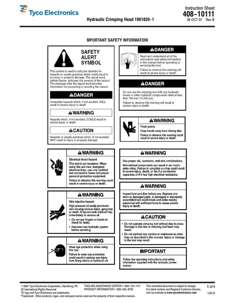
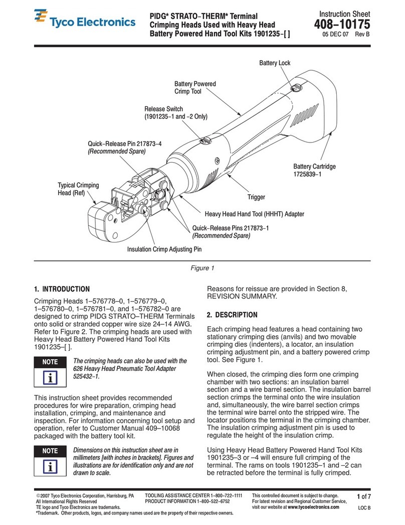
Tyco Electronics PRO-CRIMPER III User manual
Other Tyco Electronics Crimping Tools manuals

Tyco Electronics
Tyco Electronics PRO-CRIMPER III User manual

Tyco Electronics
Tyco Electronics PRO-CRIMPER III User manual
Tyco Electronics
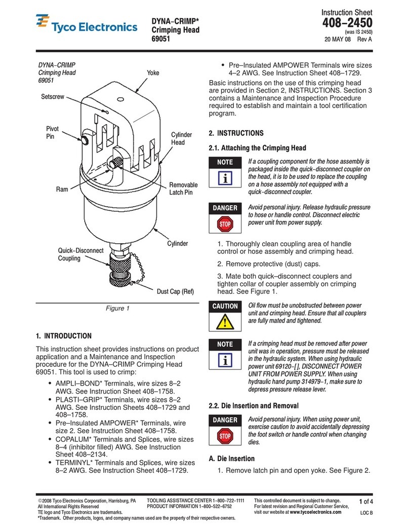
Tyco Electronics DYNA-CRIMP User manual

Tyco Electronics
Tyco Electronics 48858-1 User manual
Tyco Electronics
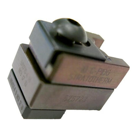
Tyco Electronics PIDG STRATO-THERM User manual
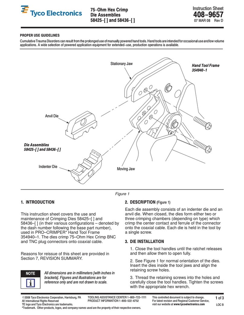
Tyco Electronics
Tyco Electronics 58425 Series User manual
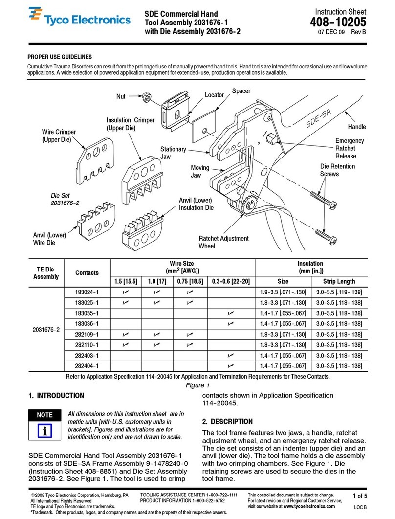
Tyco Electronics
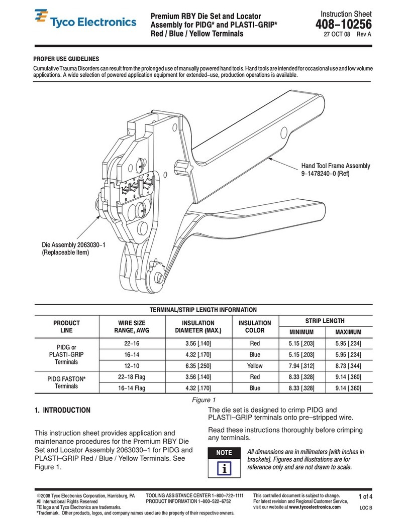
Tyco Electronics 408-10205 User manual

Tyco Electronics
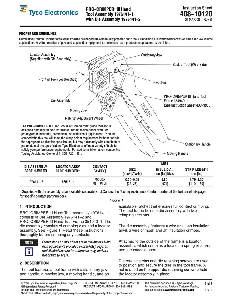
Tyco Electronics PRO-CRIMPER III User manual
Tyco Electronics
Tyco Electronics PIDG Series User manual

Tyco Electronics
Tyco Electronics SIMEL Autocoup CC040 Cof. + charg. User manual

Tyco Electronics
Tyco Electronics PRO-CRIMPER III User manual

Tyco Electronics
Tyco Electronics 58613-1 User manual
Tyco Electronics
Tyco Electronics PRO-CRIMPER III User manual

Tyco Electronics
Tyco Electronics PRO-CRIMPER III User manual

Tyco Electronics
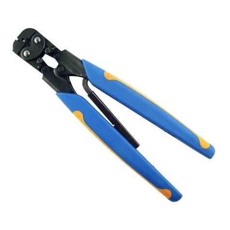
Tyco Electronics PRO-CRIMPER III User manual
Tyco Electronics
Tyco Electronics 90015 User manual
Tyco Electronics
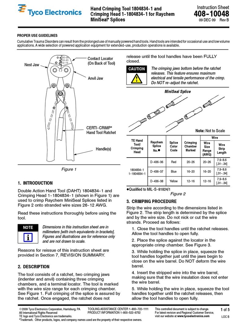
Tyco Electronics 1804834-1 User manual

Tyco Electronics
Tyco Electronics PRO- CRIMPER III User manual

Tyco Electronics
Tyco Electronics 90035-3 User manual

Tyco Electronics
Tyco Electronics 408-10050 User manual
Popular Crimping Tools manuals by other brands

Continental Refrigerator
Continental Refrigerator PC150HD quick start guide

TE Connectivity
TE Connectivity ERGOCRIMP 1-1579001-3 instruction sheet

Emerson
Emerson Klauke ES 105CFB manual
TE Connectivity
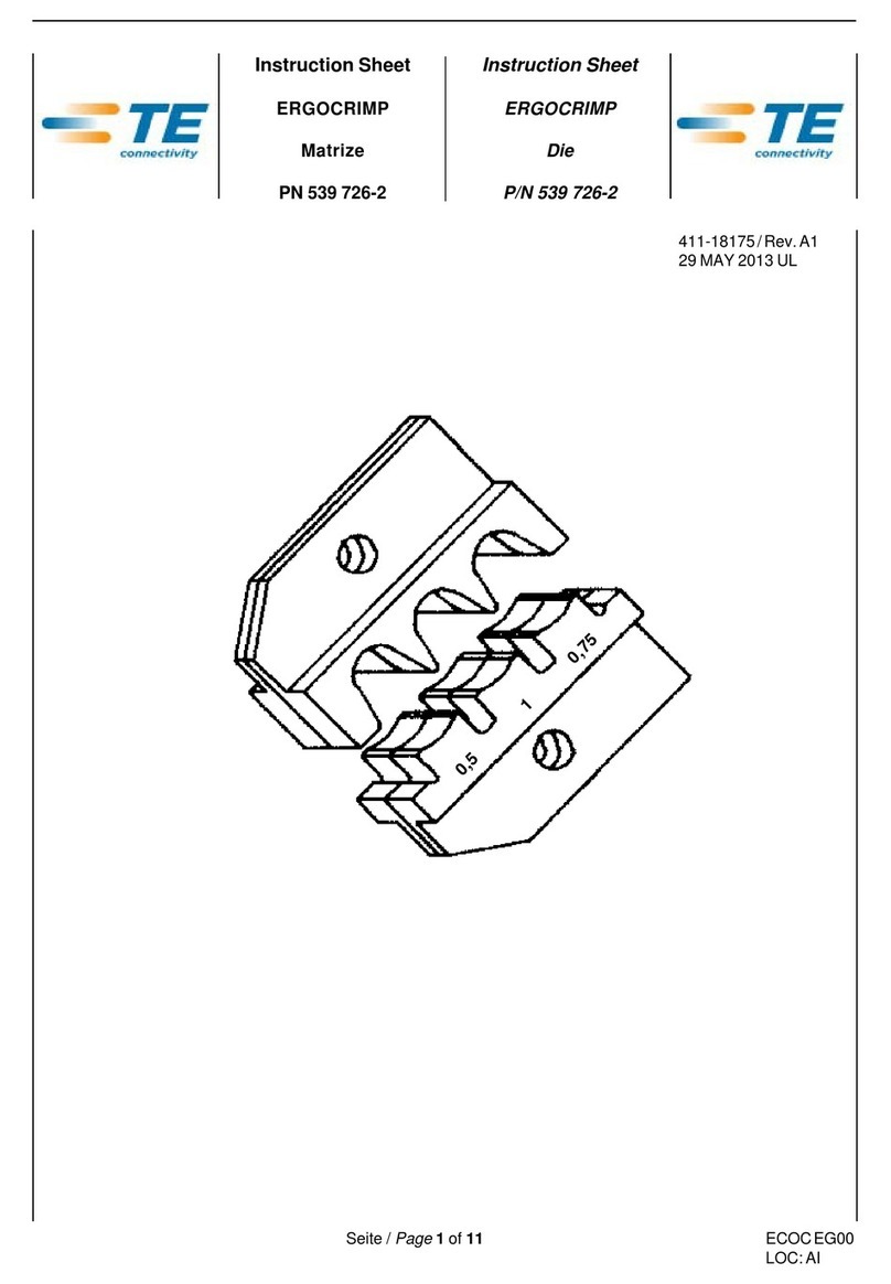
TE Connectivity 539 726-2 instruction sheet

molex
molex 207129 Series Specification sheet
TE Connectivity
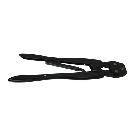
TE Connectivity 46447 instruction sheet
