manuals.online logo
Brands
  1. Home
  2. •
  3. Brands
  4. •
  5. Tyco Electronics
  6. •
  7. Crimping Tools
  8. •
  9. Tyco Electronics PRO-CRIMPER III User manual

Tyco Electronics PRO-CRIMPER III User manual

Instruction Sheet
PRO-CRIMPER* III Hand Tool Assem ly
58573-1 with Crimping Die Assem ly 408-4251
E
2005 Tyco Electronics Corporation, Harrisburg, A
All International Rights Reserved
AM and Tyco are trademarks. *Trademark
Other products, logos, and company names used are the property of their respective owners. LOC B
1
of 4
TOOLING ASSISTANCE CENTER 1-800-722-1111
RODUCT INFO 1-800-522-6752 This controlled document is subject to change.
For latest revision and Regional Customer Service,
visit our website at
www.tycoelectronics.com
07 A R 05 Rev C
58573-2 for Spare Wire Caps
PROPER USE GUIDELINES
CumulativeTraumaDisorderscanresultfromthe prolongeduseofmanually poweredhandtools.Hand toolsareintendedfor occasionaluseandlowvolume
applications. A wide selection of powered application equipment for extended-use, production operations may be available.
Figure 1
Die Retaining
Screws
RO-CRIM ER* III
Hand Tool Frame
354940-1
Die Assembly
58573-1
Stationary Jaw
Moving Jaw
Ratchet
Adjustment
Wheel
Stationary
Handle
Moving
Handle
1. INTRODUCTION
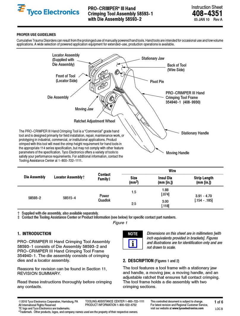
This instruction sheet covers the use of
PRO–CRIMPER III Hand Tool 58573–1 with Crimping
Die Assembly 58573–2, which is used to apply the
standard and moisture resistant spare wire caps listed
in Figure 2. The die assembly is designed to be used
in PRO–CRIMPER III Hand Tool Frame 354940–1
(shown in Figure 1). For instructions concerning the
operation of the hand tool, refer to Instruction Sheet
408–9930, which is supplied with the tool.
Measurements are in millimeters [followed by
inch equivalents in brackets].
Reasons for reissue of this document are provided in
Section 8, REVISION SUMMARY.
2. DESCRIPTION
(Figure 1)
Each die assembly consists of an indenter die and an
anvil die. When closed, the dies form four crimping
chambers, which coincide with the four sizes of spare
wire caps. Die retaining screws are used to secure
the dies in the tool frame.
The tool features a tool frame with a stationary jaw
and handle, a moving jaw, a moving handle, and an
adjustable ratchet that ensures full contact crimping.
For Single Unstripped
Wire (Thin Copper Insert)
With or Without Moisture-
Resistant Inhibitor
WIRE
INSUL
SPARE WIRE CAP No's CAP TOOL
COLOR
INSUL
.
DIA.
RANGE STANDARD MOISTURE
RESISTANT
COLOR
CODE
COLOR
CODE
DOT
1.22 - 1.91
[.048 - .075] 324484 324693 WHITE WHITE
2.03 - 2.92
[.080 - .115] 324485 324694 RED RED
3.05 - 3.68
[.120 - .145] 324486 324695 BLUE BLUE
3.81 - 5.33
[.150 - .210] 324487 324696 YELLOW YELLOW
Figure 2
NOTE
408-4251
PRO-CRIMPER III Hand Too Assemb y 58573-1
R v
C2
of 4
Figure 3
Tool Jaws
(R f)
Di Ass mbly
PRO-CRIMPER II
Hand Tool Fram
Ass mbly 354940-1
Di
R taining
Scr ws
Ind nt r
Anvil
3. DIE INSTALLATION
1. Close the tool handles until the ratchet releases,
then allow the handles to open fully.
2. Insert the dies into the tool jaws as shown in
Figure 3, and align the die retaining holes in each
die with the associated holes in the tool.
3. Thread, but do not tighten, the die retaining
screws into the holes.
4. Carefully close the tool handles, making sure
that the dies align properly.
5. Tighten the die retaining screws.
4. CRIMPING PROCEDURE
1. Refer to Figure 2, and select a cap of the
correct size for the insulation diameter of the wire
being used.
2. Identify the color code of the cap, and insert the
cap into the crimping chamber with the same color
code. Be sure that the cap is fully inserted.
3. Begin closing the tool handles until the cap is
held firmly in place. Do NOT deform the cap.
4. Insert the unstripped wire completely into the
cap.
When bottoming the wire in a moisture-resistant
cap, greater insertion force must be exerted on
the wire to displace the inhibitor present in the
cap.
5. Close the tool handles until the ratchet releases.
6. Allow the tool handles to open FULLY and
remove the crimped cap from the crimping
chamber by turning the cap and wire 1/4 turn while
pulling lightly on the wire.
Damaged products may not be used. If a
damaged product is evident, it must be replaced.
5. CRIMP INSPECTION
(Figur 4)
Inspect the crimped spare wire cap. The crimp should
be near the center of the insert in the cap, and the
wire should be bottomed in the cap.
Double check that the correct cap was used for the
wire’s insulation diameter, and make sure that the
correct crimping chamber was used.
If the cap fails inspection, remove the cap by cutting
the wire, then apply a new cap to the wire by carefully
following the above procedure.
Figure 4
Wir bottom d in cap.
1Crimp n ar c nt r of ins rt. (Cap was fully bottom d in
di closur .)
2Corr ct wir insulation diam t r for cap
b ing us d.
3
4Cap insulation color match s di closur color dot cod .
1
3
4
2
NOTE
CAUTION
408-4251
PRO-CRIMPER III Hand Tool Assembly 58573-1
3
of 4Rev
C
DC
B
A
HAND TOOL AND DIE
ASSEMBLY
DIE OPENING +0.10 .004]
ASSEMBLY
PART NUMBERS AB C D
58573-1
58573-2 1.83 [.072] 2.26 [.089] 2.95 [.116] 3.61 [.142]
Figure 5
6. MAINTENANCE AND INSPECTION
6.1. Maintenance
1. Remove dust, moisture, and other contaminants
with a clean, soft brush, or a clean, soft, lint–free
cloth. Do NOT use any objects that could damage
the dies or tool.
2. Make sure that the proper die retaining screws
are properly secured.
3. When the dies are not in use, store them in a
clean, dry area. When the tool is not in use, store it
with the handles closed to prevent objects from
being lodged within the jaws.
6.2. Inspection
1. Remove all lubrication and accumulated film
from the dies by immersing the dies in a suitable
commercial degreaser.
2. Make certain that all die retaining screws and
die components are properly secured.
3. Inspect the crimping surfaces for flattened,
chipped, worn, or cracked areas. If damage is
evident, the dies must be replaced. Refer to
Section 7, REPLACEMENT.
6.3. Measuring Die Opening
The die assembly will perform correctly as long as:
(1) the product specified is correct for the application,
(2) the specific die assembly is used, (3) the die
assembly has been measured to ensure that the
openings are correct, and (4) the die assembly
bottoms.
Figure 5 provides information on die opening sizes.
6.4. Ratchet Adjustment
(Figure 6)
The tool frame assembly ratchet mechanism features
an adjustment wheel with numbered settings. If the
crimp height is not acceptable, adjust the ratchet as
follows:
1. Remove the lockscrew from the ratchet
adjustment wheel.
2. With a screwdriver, adjust the ratchet wheel
from the opposite side of the tool.
3. Observe the ratchet adjustment wheel. If a
tighter crimp is required, rotate the adjustment
wheel COUNTERCLOCKWISE to a
higher–numbered setting. If a looser crimp is
required, rotate the adjustment wheel
CLOCKWISE to a lower–numbered setting.
4. Replace the lockscrew.
5. Make a sample crimp and measure the crimp
height. If the crimp height is acceptable, secure the
lockscrew. If the dimension is unacceptable,
remove lockscrew and continue to adjust the
ratchet, and again measure a sample crimp.
408-4251
PRO-CRIMPER III Hand Too Assemb y 58573-1
Rev
C4
of 4
Figure 6
Screwdriver
Ratchet
Adjustment
Wheel
Lockscrew
(Typ)
7. REPLACEMENT
Order replacements through your Tyco Electronics
Representative, or call 1–800–526–5142, or send a
facsimile of your purchase order to 1–717–986–7605,
or write to:
CUSTOMER SERVICE (38–35)
TYCO ELECTRONICS CORPORATION
P.O. BOX 3608
HARRISBURG, PA 17105–3608
8. REVISION SUMMARY
Since the previous release of this document, the
following changes have been made:
Per EC 0990–0465–05:
S
Updated document to corporate requirements
S
Added die set 58573–2 to title, Introduction,
and table in Figure 5
S
Changed lockscrew in Figures 1, 2, and 6
S
Changed PRO–CRIMPER II to
PRO–CRIMPER III in all instances

This manual suits for next models

2

Other Tyco Electronics Crimping Tools manuals

Tyco Electronics PRO-CRIMPER III User manual

Tyco Electronics

Tyco Electronics PRO-CRIMPER III User manual

Tyco Electronics PRO-CRIMPER III User manual

Tyco Electronics

Tyco Electronics PRO-CRIMPER III User manual

Tyco Electronics 46073 User manual

Tyco Electronics

Tyco Electronics 46073 User manual

Tyco Electronics 46121 User manual

Tyco Electronics

Tyco Electronics 46121 User manual

Tyco Electronics CERTI-CRIMP 90418-1 User manual

Tyco Electronics

Tyco Electronics CERTI-CRIMP 90418-1 User manual

Tyco Electronics SDE PEW-12 User manual

Tyco Electronics

Tyco Electronics SDE PEW-12 User manual

Tyco Electronics 408-10205 User manual

Tyco Electronics

Tyco Electronics 408-10205 User manual

Tyco Electronics PRO-CRIMPER III User manual

Tyco Electronics

Tyco Electronics PRO-CRIMPER III User manual

Tyco Electronics 90301-2 User manual

Tyco Electronics

Tyco Electronics 90301-2 User manual

Tyco Electronics PRO-CRIMPER III User manual

Tyco Electronics

Tyco Electronics PRO-CRIMPER III User manual

Tyco Electronics PRO-CRIMPER III 58517 Series User manual

Tyco Electronics

Tyco Electronics PRO-CRIMPER III 58517 Series User manual

Tyco Electronics 603995 Series User manual

Tyco Electronics

Tyco Electronics 603995 Series User manual

Tyco Electronics PRO-CRIMPER III User manual

Tyco Electronics

Tyco Electronics PRO-CRIMPER III User manual

Tyco Electronics 2-1579004-9 User manual

Tyco Electronics

Tyco Electronics 2-1579004-9 User manual

Tyco Electronics PRO-CRIMPER III User manual

Tyco Electronics

Tyco Electronics PRO-CRIMPER III User manual

Tyco Electronics 58532 Series User manual

Tyco Electronics

Tyco Electronics 58532 Series User manual

Tyco Electronics 58569-1 User manual

Tyco Electronics

Tyco Electronics 58569-1 User manual

Tyco Electronics PIDG Series User manual

Tyco Electronics

Tyco Electronics PIDG Series User manual

Tyco Electronics 90654-1 User manual

Tyco Electronics

Tyco Electronics 90654-1 User manual

Tyco Electronics PRO CRIMPER III User manual

Tyco Electronics

Tyco Electronics PRO CRIMPER III User manual

Tyco Electronics 90035-3 User manual

Tyco Electronics

Tyco Electronics 90035-3 User manual

Tyco Electronics PRO-CRIMPER III User manual
Tyco Electronics

Tyco Electronics PRO-CRIMPER III User manual

Tyco Electronics 69067 User manual

Tyco Electronics

Tyco Electronics 69067 User manual

Tyco Electronics PRO-CRIMPER III User manual

Tyco Electronics

Tyco Electronics PRO-CRIMPER III User manual
Popular Crimping Tools manuals by other brands

molex 63811-6170 Specification sheet

molex

molex 63811-6170 Specification sheet

Panduit CT-1003 OPERATION, INSPECTION and MAINTENANCE INSTRUCTIONS

Panduit

Panduit CT-1003 OPERATION, INSPECTION and MAINTENANCE INSTRUCTIONS

molex CR60927A Specification sheet

molex

molex CR60927A Specification sheet

molex 63811-8100 Specification sheet

molex

molex 63811-8100 Specification sheet

HRS HT601/TM21P-88P operating instructions

HRS

HRS HT601/TM21P-88P operating instructions

Cembre B1350-CA Operation instructions

Cembre

Cembre B1350-CA Operation instructions

TE Connectivity PRO-CRIMPER III instruction sheet

TE Connectivity

TE Connectivity PRO-CRIMPER III instruction sheet

Cable Bullet YYQ-300 instructions

Cable Bullet

Cable Bullet YYQ-300 instructions

molex 63819-1500 Specification sheet

molex

molex 63819-1500 Specification sheet

HRS HT803 instruction manual

HRS

HRS HT803 instruction manual

Staubli PV-CZM Series operating instructions

Staubli

Staubli PV-CZM Series operating instructions

TE Connectivity 68321-1 instruction sheet

TE Connectivity

TE Connectivity 68321-1 instruction sheet

molex 64001-7300 Operating Instruction Sheet And Specifications

molex

molex 64001-7300 Operating Instruction Sheet And Specifications

BEX MultiBEX mx3 instruction manual

BEX

BEX MultiBEX mx3 instruction manual

FCI HT-0525 manual

FCI

FCI HT-0525 manual

Textron Klauke EK 35/4CL manual

Textron

Textron Klauke EK 35/4CL manual

JST WC Series instruction manual

JST

JST WC Series instruction manual

Emerson Klauke MAPAX445CFM manual

Emerson

Emerson Klauke MAPAX445CFM manual

manuals.online logo
manuals.online logoBrands
  • About & Mission
  • Contact us
  • Privacy Policy
  • Terms and Conditions

Copyright 2025 Manuals.Online. All Rights Reserved.