manuals.online logo
Brands
  1. Home
  2. •
  3. Brands
  4. •
  5. Tyco Electronics
  6. •
  7. Crimping Tools
  8. •
  9. Tyco Electronics PRO-CRIMPER III User manual

Tyco Electronics PRO-CRIMPER III User manual

Instruction Sheet
PRO- CRIMPER* III Hand
Crimping Tool Assembly 58519- 1 408--9917
LOC B
1of 4
E2010 Tyco Electronics Corporation, Harrisburg, PA
All International Rights Reserved
TE logo and Tyco Electronics are trademarks.
*Trademark. Other products, logos, and company names used are the property of their respective owners.
TOOLING ASSISTANCE CENTER 1--800--722--1111
PRODUCT INFORMATION 1--800--522--6752
This controlled document is subject to change.
For latest revision and Regional Customer Service,
visit our website at www.tycoelectronics.com
22 JAN 10 Rev Bwith Die Assembly 58510- 1
PROPER USE GUIDELINES
Cumulative Trauma Disorders can result from the prolonged use of manually powered hand tools. Hand tools are intended for occasional use and low volume
applications. A wide selection of powered application equipment for extended--use, production operations is available.
Figure 1
Stationary Jaw
Movable Jaw
Emergency
Ratchet
Release
Ratchet
Adjustment
Wheel
Die Retaining
Screws
Ratchet
Adjustment
Screw
Pivot Pin
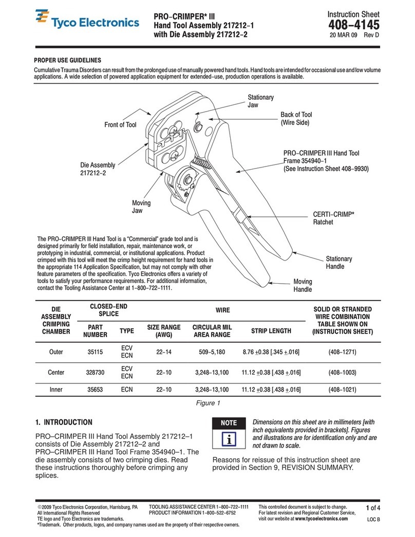
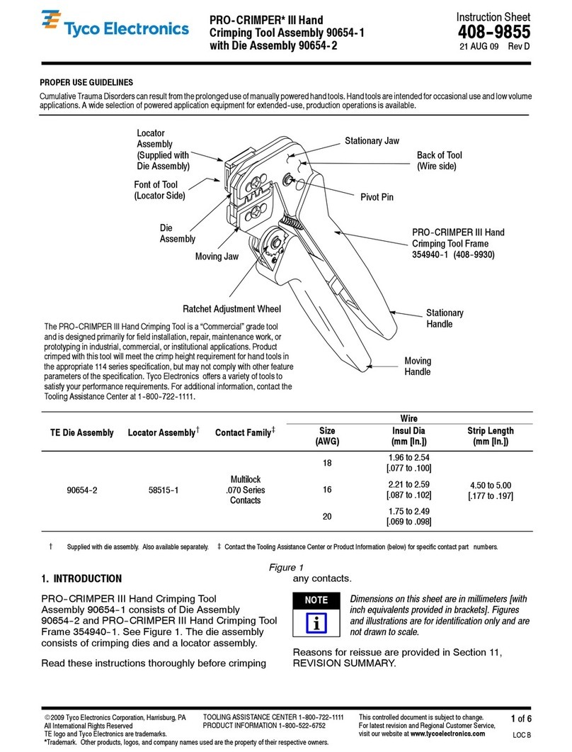
The PRO--CRIMPER III Hand Crimping Tool is a “Commercial” grade hand tool
and is designed primarily for field installation, repair, maintenance work,
or prototyping in industrial, commercial, or institutional applications. Product
crimped with this tool will meet the crimp height requirement for hand tools in the
appropriate 114 application specification, but may not comply with other feature
parameters of the specification. Tyco Electtronics offers a variety of tools to
satisfy your performance requirements. For additional information, contact the
Tooling Assistance Center at 1--800 --722--1111.
Indenter Die
Anvil Die
Crimping Die
Assembly 58510--1
PRO--CRIMPER III Hand Crimping
Tool Frame Assembly 58532--[ ]
1. INTRODUCTION
This instruction sheet provides application and
maintenance procedures for Crimping Die Assembly
58510--1. See Figure 1. When used in
PRO--CRIMPER III Hand Crimping Tool Frame
Assembly 58532--[ ] the die assembly crimps
Fixed--Shroud Duplex fiber--optic connectors with
base part numbers 501780 and 502015, and FSD
Breakout Kit Assembly 502020.
The die assembly and frame assembly together form
PRO--CRIMPER III Hand Crimping Tool Assembly
58519--1. The die assembly can be purchased
separately, or purchased with the hand tool assembly.
For connector assembly procedures, refer to
instruction sheet 408--9373 (FSD Connectors) or
408--9469 (FSD Breakout Kit Assembly). For
information concerning the use and maintenance of
Frame Assembly 58532--1, refer to instruction sheet
408--4020.
Read these and all referenced materials before using
the die assembly.
Reasons for reissue are in Section 7, REVISION
SUMMARY.
2. DESCRIPTION
The die assembly features an indenter die and an
anvil die. When closed, the dies form two crimping
chambers, which crimp the crimp ring of the
connector onto the connector strain relief and the
cable strength members. The larger crimping
chamber is used to crimp FSD connectors. Both
chambers are used for the breakout kit assembly: the
larger to crimp duplex crimp rings and the smaller to
crimp simplex crimp rings. Each die is held in the tool
jaws with a single screw. See Figure 2.
408- 9917
PRO- CRIMPER III Hand Crimping Tool Assembly 58519- 1
Rev B2 of 4 Tyco Electronics Corporation
Figure 2
Stationary Jaw
Indenter Die
Anvil Die Movable
Jaw Ratchet
Die--Retaining
Screws
3. DIE INSTALLATION (Figure 2)
1. Close the tool handles until the ratchet releases;
then allow the tool handles to open FULLY.
2. Install anvil die in the movable jaw of the tool
frame. Align the die with the retaining screw hole;
then secure die with the die--retaining screw. Do
NOT fully tighten.
3. Install indenter die in the stationary jaw of the
tool frame. Slowly close the tool handles, allowing
the dies to align themselves. When dies are
properly aligned, securely tighten both screws with
the appropriate hex wrench.
4. CRIMPING PROCEDURE (Figure 3)
Prepare connector and cable according to the
instructions packaged with the connector, and
proceed as follows:
1. Close the tool handles until the ratchet releases;
then allow the tool handles to open FULLY.
2. Place the strain relief assembly (with the outer
crimp ring in place) in the appropriate crimping
chamber so that the flange of the strain relief rests
against the sides of the die. See Figure 3.
3. Close the tool handles until the ratchet releases;
then open the tool handles to remove the crimped
connector.
5. MAINTENANCE/INSPECTION
5.1. Maintenance
1. Remove dust, moisture, and other contaminants
with a clean, soft brush, or a clean, soft, lint--free
cloth. Do NOT use any objects that could damage
the dies or tool.
2. Make sure that the proper die--retaining screws
are properly secured.
3. When the dies are not in use, store them in a
clean, dry area.
4. Store the tool with the tool handles closed to
prevent objects from becoming lodged within the
jaws.
5.2. Inspection
1. Remove all lubrication and accumulated film
from the dies by immersing the dies in a suitable
commercial degreaser.
2. Make certain that all die--retaining screws and
die components are properly secured.
3. Inspect the crimping surfaces for flattened,
chipped, worn, or cracked areas. If damage is
evident, the dies must be replaced. Refer to
Section 6, REPLACEMENT.
408- 9917
PRO- CRIMPER III Hand Crimping Tool Assembly 58519- 1
3of 4Rev BTyco Electronics Corporation
Figure 3
Fibers
Flange on
Strain Relief
Outer
Crimp Ring
5.3. Measuring Die Opening
The die assembly will perform correctly as long as:
(1) the product specified is correct for the application,
(2) the specific die assembly is used, (3) the die
assembly has been measured to ensure that the
openings are correct, and (4) the tool has been
adjusted correctly. Figure 4 provides information on
die openings.
A
(REF)
B
(REF)
Die Closure Dimensions (+.10 mm [+ .004 In.])
A B
5.44 mm [.214 in.] 8.53 mm [.336 in.]
Figure 4
5.4. Ratchet Adjustment (Figure 5)
The tool frame assembly ratchet mechanism features
an adjustment wheel with numbered settings. If the
crimp is not acceptable, adjust the ratchet as follows:
1. Remove the lockscrew from the ratchet
adjustment wheel.
2. With a screwdriver, adjust the ratchet wheel
from the opposite side of the tool.
3. Observe the ratchet adjustment wheel. If a
tighter crimp is required, rotate the adjustment
wheel COUNTERCLOCKWISE to a
higher--numbered setting. If a looser crimp is
required, rotate the adjustment wheel
CLOCKWISE to a lower--numbered setting.
4. Replace the lockscrew.
5. Make a sample crimp and measure the crimp
height. If the crimp is acceptable, replace and
secure the lockscrew. If the dimension is
unacceptable, continue to adjust the ratchet, and
again measure a sample crimp.
Figure 5
Screwdriver
Ratchet
Adjustment
Wheel
Lockscrew
(Typ)
6. REPLACEMENT
Crimping Die Assembly 58510--1 was inspected
before shipment. Tyco Electronics recommends that
the dies be inspected immediately upon arrival at your
facility to ensure that the dies have not been
damaged during shipment.
Available separately, PRO--CRIMPER III Hand
Crimping Tool Repair Kit 679221--1 includes a
replacement nut and a variety of pins, rings, screws,
and springs.
If the dies are damaged or worn excessively, they
must be replaced.
408- 9917
PRO- CRIMPER III Hand Crimping Tool Assembly 58519- 1
Rev B4 of 4 Tyco Electronics Corporation
Order the repair kit and replaceable parts through
your Tyco Electronics representative, or call
1--800--526--5142, or send a facsimile of your
purchase order to 1--717--986--7605, or write to:
CUSTOMER SERVICE (38--35)
TYCO ELECTRONICS
PO BOX 3608
HARRISBURG PA 17105--3608
7. REVISION SUMMARY
Revisions to this instruction sheet include:
SChanged PRO--CRIMPER II to
PRO--CRIMPER III Hand Tool;
SApplied TE logo; and
SUpdated format to current corporate
requirements.
PRO-CRIMPER III Hand Tool 354940- 1
(Instruction Sheet 408-9930)
SDE-SA Hand Tool 9-1478240- 0
(Instruction Sheet 408-8851)
SDE Bench Terminator 1490076- 2
(Customer Manual 409-10052)
SDE Bench Terminator 1490076- 2
(Customer Manual 409-10052)
Battery Tool (Pin Die) 1213890- 1, - 2
(Customer Manual 409-10065)
Battery Tool (Shouldered Die) 1725837-1, -2
(Customer Manual 409-10053)
Tooling Compatible With Die Assembly 58510- 1

This manual suits for next models

2

Other Tyco Electronics Crimping Tools manuals
Tyco Electronics PRO-CRIMPER III User manual

Tyco Electronics

Tyco Electronics PRO-CRIMPER III User manual

Tyco Electronics 58532 Series User manual

Tyco Electronics

Tyco Electronics 58532 Series User manual

Tyco Electronics 46121 User manual

Tyco Electronics

Tyco Electronics 46121 User manual

Tyco Electronics PRO-CRIMPER III User manual

Tyco Electronics

Tyco Electronics PRO-CRIMPER III User manual

Tyco Electronics PIDG STRATO-THERM User manual

Tyco Electronics

Tyco Electronics PIDG STRATO-THERM User manual

Tyco Electronics 69067 User manual

Tyco Electronics

Tyco Electronics 69067 User manual

Tyco Electronics 45449 User manual

Tyco Electronics

Tyco Electronics 45449 User manual

Tyco Electronics PRO-CRIMPER III User manual

Tyco Electronics

Tyco Electronics PRO-CRIMPER III User manual

Tyco Electronics 408-10050 User manual

Tyco Electronics

Tyco Electronics 408-10050 User manual

Tyco Electronics 69156-1 User manual

Tyco Electronics

Tyco Electronics 69156-1 User manual

Tyco Electronics PRO-CRIMPER III User manual

Tyco Electronics

Tyco Electronics PRO-CRIMPER III User manual

Tyco Electronics PRO-CRIMPER III User manual

Tyco Electronics

Tyco Electronics PRO-CRIMPER III User manual

Tyco Electronics AMP PRO–CRIMPER II User manual

Tyco Electronics

Tyco Electronics AMP PRO–CRIMPER II User manual

Tyco Electronics PRO-CRIMPER II User manual

Tyco Electronics

Tyco Electronics PRO-CRIMPER II User manual

Tyco Electronics PRO-CRIMPER III User manual

Tyco Electronics

Tyco Electronics PRO-CRIMPER III User manual

Tyco Electronics PRO-CRIMPER III User manual

Tyco Electronics

Tyco Electronics PRO-CRIMPER III User manual

Tyco Electronics 1490748-1 User manual

Tyco Electronics

Tyco Electronics 1490748-1 User manual

Tyco Electronics PRO CRIMPER III User manual

Tyco Electronics

Tyco Electronics PRO CRIMPER III User manual

Tyco Electronics PRO-CRIMPER III User manual
Tyco Electronics

Tyco Electronics PRO-CRIMPER III User manual

Tyco Electronics 9-1478246-0 User manual

Tyco Electronics

Tyco Electronics 9-1478246-0 User manual

Tyco Electronics 90654-1 User manual

Tyco Electronics

Tyco Electronics 90654-1 User manual
Tyco Electronics 2063811-1 User manual

Tyco Electronics

Tyco Electronics 2063811-1 User manual

Tyco Electronics CERTI-CRIMP II User manual

Tyco Electronics

Tyco Electronics CERTI-CRIMP II User manual

Tyco Electronics 1213850-1 User manual

Tyco Electronics

Tyco Electronics 1213850-1 User manual

Popular Crimping Tools manuals by other brands

Panduit BlackFin CT-2600/LBT instruction manual

Panduit

Panduit BlackFin CT-2600/LBT instruction manual

ODU 080.000.048.000.000 instruction manual

ODU

ODU 080.000.048.000.000 instruction manual

TE Connectivity 2381454-1 Guidelines

TE Connectivity

TE Connectivity 2381454-1 Guidelines

TE Connectivity SDE-SA instruction sheet

TE Connectivity

TE Connectivity SDE-SA instruction sheet

molex 63827-5470 Specification sheet

molex

molex 63827-5470 Specification sheet

TE Connectivity HDP-400 Customer's manual

TE Connectivity

TE Connectivity HDP-400 Customer's manual

Rennsteig PEW15 owner's manual

Rennsteig

Rennsteig PEW15 owner's manual

Staubli CT-CP Assembly instructions

Staubli

Staubli CT-CP Assembly instructions

HYDROSCAND H24DC user manual

HYDROSCAND

HYDROSCAND H24DC user manual

molex 63825-9400 Application Tooling Specification Sheet

molex

molex 63825-9400 Application Tooling Specification Sheet

Stanley DUBUIS KW Hydraulik BPL031 instruction manual

Stanley

Stanley DUBUIS KW Hydraulik BPL031 instruction manual

Ilsco TASKMASTER TB-6DF1000-P instruction manual

Ilsco

Ilsco TASKMASTER TB-6DF1000-P instruction manual

Hilti NURON NCR 120-22 manual

Hilti

Hilti NURON NCR 120-22 manual

TE Connectivity TERMI-FOIL 68026 instruction sheet

TE Connectivity

TE Connectivity TERMI-FOIL 68026 instruction sheet

KIMBALL MIDWEST 27-799 instruction manual

KIMBALL MIDWEST

KIMBALL MIDWEST 27-799 instruction manual

Samtec CAT-HT-169-2024-11 quick start guide

Samtec

Samtec CAT-HT-169-2024-11 quick start guide

TE Connectivity 575937 instruction sheet

TE Connectivity

TE Connectivity 575937 instruction sheet

Staubli PV-CZM Series operating instructions

Staubli

Staubli PV-CZM Series operating instructions

manuals.online logo
manuals.online logoBrands
  • About & Mission
  • Contact us
  • Privacy Policy
  • Terms and Conditions

Copyright 2025 Manuals.Online. All Rights Reserved.