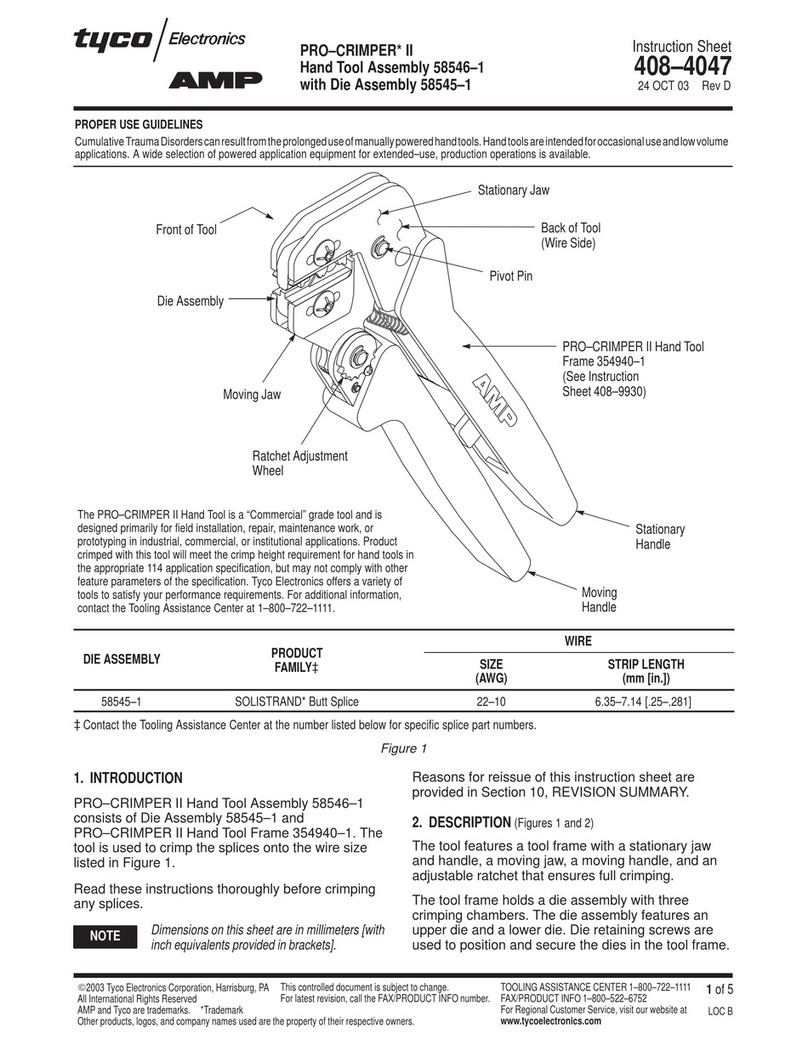
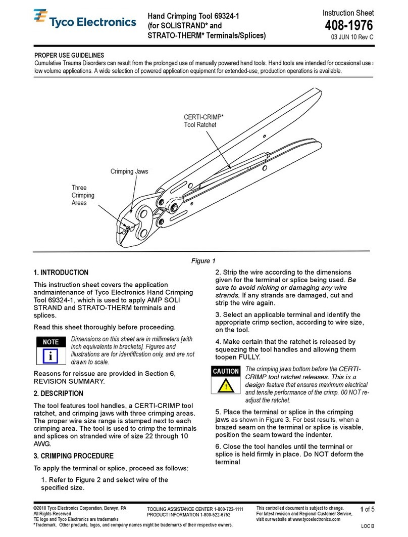
Tyco Electronics PRO-CRIMPER III 58517 Series User manual
Other Tyco Electronics Crimping Tools manuals
Tyco Electronics
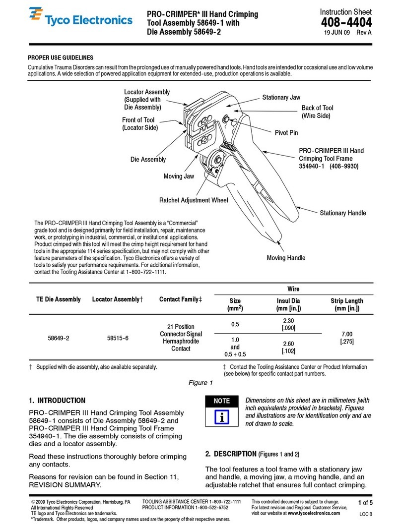
Tyco Electronics 58649-1 User manual
Tyco Electronics
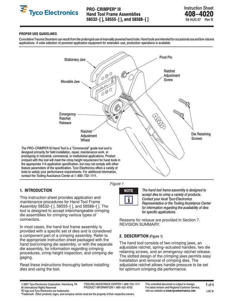
Tyco Electronics 58532 Series User manual

Tyco Electronics
Tyco Electronics PRO CRIMPER III User manual

Tyco Electronics
Tyco Electronics PRO-CRIMPER III User manual

Tyco Electronics
Tyco Electronics PRO-CRIMPER III User manual
Tyco Electronics
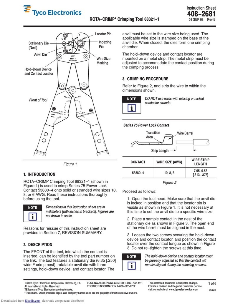
Tyco Electronics ROTA-CRIMP 68321-1 User manual
Tyco Electronics
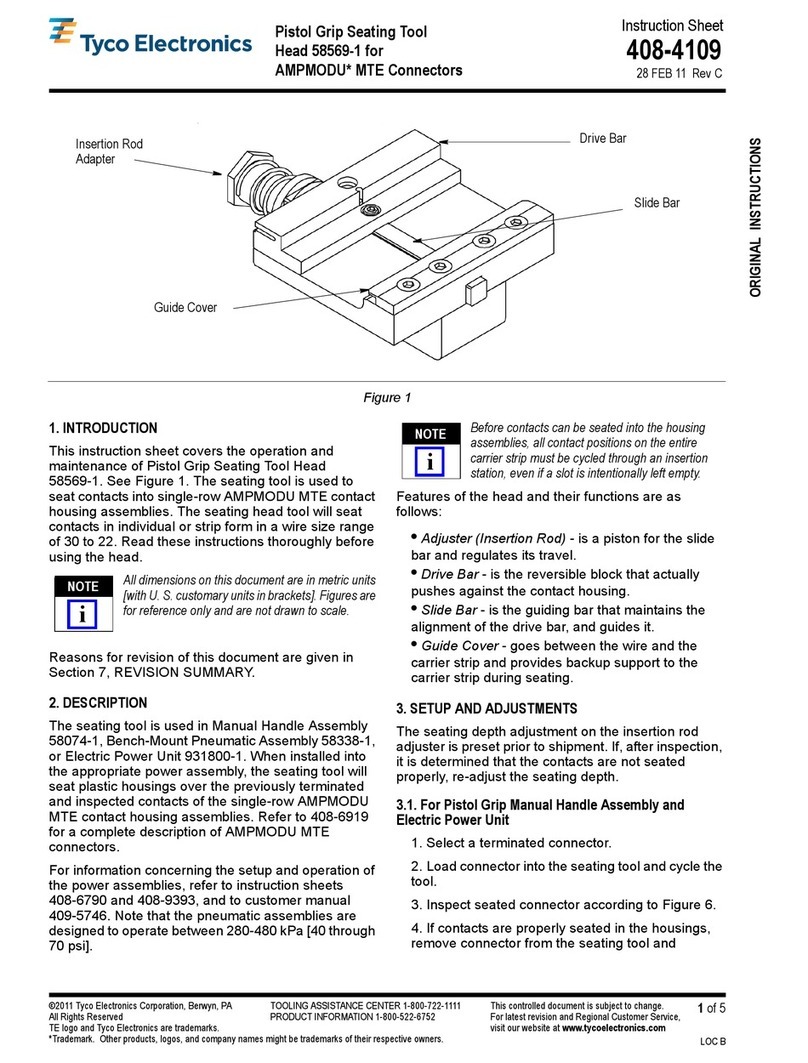
Tyco Electronics 58569-1 User manual
Tyco Electronics
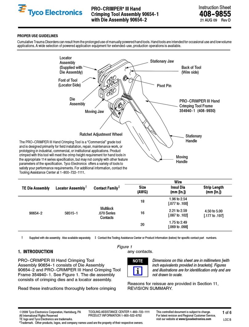
Tyco Electronics 90654-1 User manual

Tyco Electronics
Tyco Electronics PRO-CRIMPER III User manual
Tyco Electronics
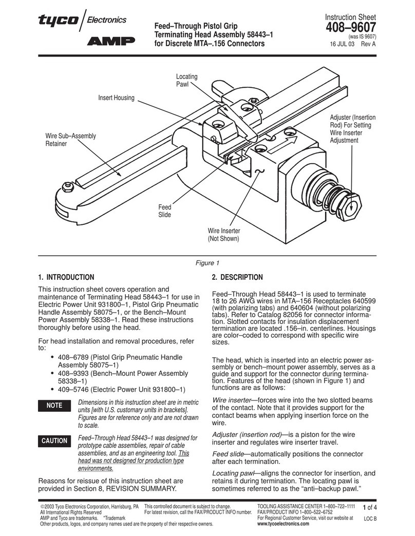
Tyco Electronics 58443-1 User manual

Tyco Electronics
Tyco Electronics 58613-1 User manual

Tyco Electronics
Tyco Electronics PRO-CRIMPER III User manual

Tyco Electronics
Tyco Electronics AMP CERTI-CRIMP II User manual

Tyco Electronics
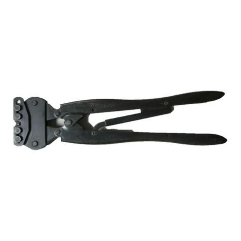
Tyco Electronics AMP PRO–CRIMPER II User manual
Tyco Electronics
Tyco Electronics 46073 User manual

Tyco Electronics
Tyco Electronics 90015 User manual

Tyco Electronics
Tyco Electronics PRO-CRIMPER III User manual

Tyco Electronics
Tyco Electronics PRO-CRIMPER III User manual

Tyco Electronics
Tyco Electronics 1752787-1 User manual

Tyco Electronics
Tyco Electronics CERTI-CRIMP 90418-1 User manual
Popular Crimping Tools manuals by other brands

Continental Refrigerator
Continental Refrigerator PC150HD quick start guide

TE Connectivity
TE Connectivity ERGOCRIMP 1-1579001-3 instruction sheet

Emerson
Emerson Klauke ES 105CFB manual
TE Connectivity
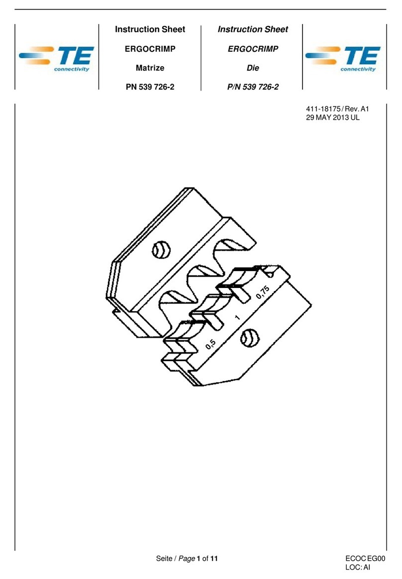
TE Connectivity 539 726-2 instruction sheet

molex
molex 207129 Series Specification sheet
TE Connectivity
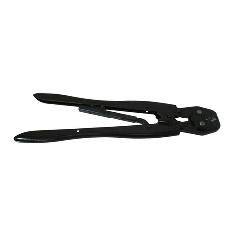
TE Connectivity 46447 instruction sheet


