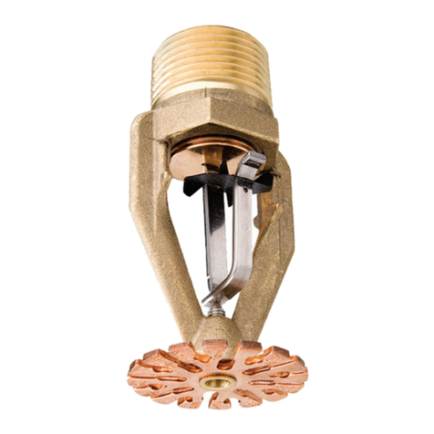
Tyco Grinnell FR-1 User manual

HORIZONTAL SIDEWALL SPRINKLERS
140°F REWQR-EC & 165°F REWQR-EC/EC
MODEL FR-1, FAST RESPONSE SOLDER TYPE, 17/32” (20 mm) ORIFICE
The 17132 inch (20 mm) orifice, Model
FR-1 140-F RES/QR-EC & 165’F
RES/QR-EC/EC Horizontal Sidewall
Sprinklers (Ref. Figure A) are auto-
matic sprinklers of the fusible solder
type. They are intended to be used in
l wet pipe residential sprinkler sys-
tems for one- and two-family dwell-
ings and mobile homes per NFPA
13D,
l wet pipe residential sprinkler sys-
tems for residential occupancies up
y3;ur stories in height per NFPA
t
l wet pipe sprinkler systems for the
residential portions of any occu-
pancy per NFPA 13,
l light hazard, quick response - ex-
tended coverage @R-EC) sprinkler
system applications per NFPA 13 or
FM installation standards, or
l light hazard, extended coverage
(EC) sprinkler system applications
per NFPA or FM installation stan-
dards.
They are designed for installation
along a wall or lintel and just beneath
a smooth ceiling. Horizontal sidewall
sprinklers are generally used in lieu of
pendent or upright sprinklers because
of aesthetic, building construction, or
installation economy considerations.
The FR-1 Sprinklers have been de-
signed to operate with a particular fus-
ible element temperature rating and
heat sensitivity characteristic, as well
as to discharge water in a specific pat-
tern and quantity per square foot rela-
tionship. The combination of the per-
formance characteristics which are
associated with the FR-1 Sprinklers
have been proven to help in the control
of residential type fires and, therefore,
to improve the chance for occupants to
escape or be evacuated.
Fire sprinkler systems are not a substi-
tute for intelligent fire safety aware-
ness or construction materials and
practices required by building codes.
The 17/32 inch (20 mm) orifice, Model
FR-1 Horizontal Sidewall Sprinklers
Components:
1 - Frame
2 - Strut
3 - Deflector
4-Hook
5 - Link
Assembly
6 - Eiection
Spring
7 - Button
6 - Gasketed
Spring
Plate
t
l-l/2”
(38.lmm)
1 /TEMPERATURE CENTERLINE
RATING OF WATERWAY -
1/2”(12.7mm)MAKE-IN
7/16”
(I I.lnwn)
NOMINAL
FIGURE A
17/32 INCH (20 mm) ORIFICE MODEL FR-1
140-F RESIQR-EC &?I165’F RES/QR-EC/EC
HORIZONTAL SIDEWALL SPRINKLERS
are listed by Underwriters Labora- The 17/32 inch (20 mm) orifice, Model
tories Inc. and Underwriters’ Labora- FR-1 Horizontal Sidewall Sprinklers
tories of Canada, and they are ap- are accepted by the City of New York
proved bv Factorv Mutual Research under MEA 39-92-M.
i=orporatibn. The listings only apply to
the service conditions indicated in the Any questions concerning an interpre-
General Technical Data and Installa- tation of NFPA 13, 13D, or 13R sprink-
tion/Usage sections. ler system design/installation stan-
Printed in U.S.A. 3-95 TD589
OBSOLETE

APPLICATION
REda)
QR-Edb)
EC@)
, SPRINKLER LOCATIONS
\I \ -w-7---7 ’
----!---
Tl I
+ ; ---------_________ I
-I----\---,_-_-:-------
--
I
LI!tT i <C- 17’ (5,Zm) i<
MINIMUM “-+jdL
I 2-y B- IO’ (3,l ml
-1..-.. MINIMUM
___--- --..__ I
__---- ---,I-..
I
/’ ---.._._
I -0’
LIMITS OF SINGLE
;;;I;KLER COVERAGE CEILING DISTANCE
NOTES:
(a) Wet pipe fire sprinkler systems in the residential portions of any occupancy per NFPA 13,
in one- and two- family dwellings and mobile homes per NFPA 13D, or residential
occupancies per NFPA 13R.
(b) For use in QR-EC and EC Light Hazard Occupancy automatic sprinkler system applica-
tions per NFPA 13.
(c) For use in EC Light Hazard Occupancy automatic sprinkler system applications per NFPA
13.
(d) UL and ULC requirements are based on minimum flow in GPM from each sprinkler. The
residual pressures are indicated for reference purposes and are based on a nominal
K-factor of 8.1 (116,8).
(e) Single Head/Multiple Head flow rates [for example: the minimum single sprinkler flow rate
is 26 GPM (98 LPM) and the minimum multiple sprinkler flow rate is 24 GPM (91LPM)
per sprinkler for a maximum coverage area of 12’ x 12’ (3,7 m x 3,7 m)]. Refer to Hydraulic
Design Criteria under Residential InstallationiUsage Criteria Section for details.
(f) The centerline of the sprinkler waterway is located 7/16 inch (11,l mm) below the deflector
(Ref. Figure A).
(g) Ceiling is to slope downwards from the wail on which the sprinkler is located.
TABLE A-l
UL AND ULC LISTING CRITERIA FOR INSTALLATION
OF THE 17/32 INCH (20 mm) ORIFICE
MODEL FR-1 HORIZONTAL SIDEWALL SPRINKLERS
-2-
REFER TO TABLE A-l
ESCUTCHEON
2 lo 6” (50 to 150mm)
EXCEPT THAT DISTANCE IS TO BE
2 to 3” (50 to 75 mm)
FOR SOFFIT MOUNTING IN
RESIDENTIAL APPLICATIONS
FIGURE B-1
WALL MOUNTING DIMENSIONS
FOR INSTALLATIONS PER
NFPA STANDARDS
dards, as well as requests for system
design/installation standards not pres-
ently covered by NFPA 13, 130, or
13R, should be addressed to the:
Secretary, Standards Council
National Fire Protection Association
Batterymarch Park
Quincy, MA 02269
WARNINGS
The Model FR-1 Horizontal Side-
wall Sprinklers described herein
must be installed and maintained
in compliance with this docu-
ment, as well as with the applica-
f DuPont Registered Trademark
OBSOLETE

DEFLECTOR-TO- MAX.
APPLICATION COVER&i;: AREA “F:“d;Yv pp!$!k;;$ (b, CEILINGA~l~TANCE SPRINKLER Ez
FT.xFT.(mxm) GPM (LPM) PSI (BAR) INWE; (mm) TEMP*PFATING INJFT.
(mrrW
16x16(4,9x4,9) 32 (12,l) 16 (1,lO) 4 to 12 (100 to 300) 165 1 (83)
16x18(4,9x5.5) 36 (136) 20 (1,38) 4 to 12 (100 to 300) 165 1 (83)
QR-EC@ 16 x 20 (4.9 x 6,l) 40 (151) 25 (1,72) 4to12(100to300) 165 1 (83)
16 x 22 (4,9 x 6,7) 44 (167) 30 (2,06) 4to12(100to300) 165 1 (83)
. , 16 x 24 (4,9x 7,3) , 48(182) , 36 (2,48) , 4 to 12 to
(100 300) , 165 . 1 (83) .
*DEFLECTOR-TO-
CEILING DISTANCE
NOTES:
(a) For use in W-EC and EC Light Hazard Occupancy automatic sprinkler system applica-
tions per FM installation standards. (Maximum room size: 1600 ft2 (150 m*) except for
corridors protected by one row of sprinklers. Minimum fire-resistance rating of room walls:
30 minutes.)
(b) FM requirement is based on maintaining both minimum flow and minimum pressure.
(c) The centerline of the sprinkler waterway is located
7/16 inch (11,l mm) below the deflector (Ref. Figure A).
TABLE A-2
FM APPROVAL CRITERIA FOR INSTALLATION
OF THE 17/32 INCH (20 mm) ORIFICE
MODEL FR-1 HORIZONTAL SIDEWALL SPRINKLERS
ble standards of the National Fire
Protection Association, in addi-
tion to the standards of any other
authorities having jurisdiction.
Failure to do so may impair the
integrity of these devices.
Because of the above cited stipu-
lations and the varied nature of
residential type architecture,
there will be some compartment
designs which cannot be fully
sprinklered in accordance with
the recommendations of NFPA 13,
130, or 13R. In the event of this
condition, consult the authorities
having jurisdiction for guidance.
It is the responsibility of an in-
stalling contractor to provide a
copy of this document to the owner
or his representative and, in turn,
it is the obligation of the owner to
provide a copy of this document to
a succeeding ownen
The owner is responsible for
maintaining their fire protection
system and devices in proper op-
erating condition. The installing
contractor or sprinkler manufac-
turer should be contacted relative
to any questions.
Sprinkler Assemblies:
The 17/32 inch (20 mm) orifice, Model
FR-1 Horizontal Sidewall Sprinklers
are available in 14O’F/57’C (REWQR-
EC) and 165’F/74’C (REWQR-
EC/EC) temperature ratings with natu-
ral brass or chrome plated finishes.
The Link Assembly for both finishes is
provided with a black coating, for min-
imum obtrusiveness. The FR-1 Sprink-
lers are rated for use at a maximum
service pressure of 175 psi (12,l bar).
The nominal discharge curve plotted in
Figure C represents the flow “Q” in
GPM (LPM) as determined by the for-
mula:
Q=K$
where the nominal discharge coeffi-
cient “K” equals 8.1 (116,8); and, “p”
equals the residual flowing pressure in
psi (bar). Listing standards permit the
-3-
CENTERLINE
OF SPRINKLER
2 to 2-314” (5010 70 mm)
WHICH PROVIDES A HEAT
RESPONSIVE ELEMENT TO
MOUNTING SURFACE DISTANCE
OF 3/4 to l-l/2” (20 to 40 mm)
FIGURE B-2
WALL MOUNTING DIMENSIONS
FOR INSTALLATIONS PER
FMSTANDARDS
FIGURE C
NOMINAL DISCHARGE CURVE
L
actual value of K to vary from 7.4 to 8.2
(106,7 to 118,2).
The Frame of the FR-1 is a die cast
bronze per ASTM 8176 (C87800). The
OBSOLETE

/DEFLECTOR-TO-CEILING: 4 INCHES 0’ h //-DEFLECTOR-TO-CEILING DISTANCE: 4 INCHES
0' 4’ 8’
CENTERLINE OF 16’ X 16’ COVERAGE AREA’
/DEFLECTOR-TO-CEILING: I8lNCHES
/BACK WALL
SIDEWALL \
6’
i \ 1-q
8’ 12’ \ 16’ 18’
CENTERLINE OF 16’ X 18’ COVERAGE AREA1
/DEFLECTOR-TO-CEILING: 4 INCHES
LCK WALL SIDEWALL \
CENTERLINE OF 16’ X 24’ COVERAGE AREA\
NOTES:
I. Patterns shown with no ceiling mounted obstructions.
2. See QR-EC & EC Installation/Usage Criteria and War-
-
-K 4’,BACK WALL
6’
8’
/ / \ \ w
0' 4’ 8’ 12’ 16’ 20’
CENTERLINE OF 16’ X 20’ COVERAGE AREA ’
,DEFLECTOR-TO-CEILING: 4 INCHES
CENTERLINE OF 20’ X 16’ COVERAGE AREA /
/DEFLECTOR-TO-CEILING: 4 INCHES
0 BACK WAL
8’ SIDEWALL\
L FAR WALL\ ,t ~0’
6’ 6’
CENTERLINE OF 16’ X 20’ COVERAGE AREA ’
FIGURE D
NOMINAL WElTlNG PAlTERNS AT UL AND ULC LISTED MINIMUM FLOW RATES
FOR REPRESENTATIVE QR-EC AND EC APPLICATIONS
ranty sectIons.
OBSOLETE

CENTERLINE OF 16’ x 20’ COVERAGE AREA1
NOTES:
1. Pattern shown with no ceiling mounted obstructions.
2. See Residential Installation/Usage Criteria and Warranty Sections.
3. Data shown for centerline of sprinkler waterway to ceiling distance of 4-7/i 6’ (112,7 mm).
FIGURE E
NOMINAL WElTlNG PATTERN AT MINIMUM REQUIRED
MULTIPLE SPRINKLER FLOW FOR 16’ i 20’ (4,s m x 6,l m)
RESIDENTIAL APPLICATIONS
lo&+c
“:‘9”’
-i
8' -20" t
i
t+i,&+
ISPRINKL
NOTES:
SIDEWALL
6’ 8’ / 10’ 12’ 14’ 16’ 18’ 20’ 22’ 24’
R kENTERLlNE OF COVERAGE AREA
PLAN VIEW
1. For a given position within the coverage area, ceiling mounted obstructions must not hang
below the elevation dimension given in the graph.
2. Elevation dimensions are perpendicular to the plane of the Deflector Hat (ref. Fig. A), where
positive (+) dimensions are above the plane of the Deflector Hat and negative (-)
dimensions are below. (Reference: the Deflector Hat is 7/16” (11,l mm) above the
sprinkler centerline of waterway.)
FIGURE F
ALLOWABLE ELEVATION FOR CEILING MOUNTED OBSTRUCTIONS
SUCH AS HEATING OR AIR CONDITIONING DIFFUSERS, OVERHANGS,
AND LIGHT FIXTURES
Strut is silicone bronze per ASTM B96
(C65500), and the Deflector is brass
per ASTM 836 (C22000). The Hook is
phosphor bronze per ASTM B159
(C51000), the two halves of the Link
Assembly are nickel, the Ejection
Spring is lnconel 600 wire per ASTM
B166, and the Button is brass per
ASTM 836 (C22000). The Gasket ma-
terial is Teflonf, and the Spring Plate
is an lnconel disc spring.
The Link Assembly has a thin, black,
resin type coating which will protect
the Link Assembly from deterioration
which could otherwise be caused by
normal atmospheres. The coating is
not intended to provide protection
against attack by corrosive media.
Escutcheon Plates:
Figures B-l and B-2, as applicable,
provide wall mounting dimensions for
the FR-1 Sprinkler and illustrate the
use of a standard one-piece escutch-
eon plate like that described in Tech-
nical Data Sheet TD805.
The FR-1 Sprinklers may be installed
with a split type escutcheon plate like
that described in TD815. The split type
plate is suitable for use with plastic
pipe fire protection systems when it is
installed in accordance with the in-
structions given in TD815.
NOTES
The standard type escutcheon
plate like that shown in Technical
Data Sheet TD805 can NOT be
used to hold the FR-1 in position.
The FR-1 must be secured in posi-
tion by firmly fastening the
sprinkler system piping to the
dwelling structure. If the FR-1 is
not properly secured in position,
reaction forces resulting’ from
sprinkler operation could alter
its orientation and water distri-
bution pattern.
Only use escutcheon plates that
will provide a deflector-to-mount-
ing surface distance within the
range specified in Figure B-l or
B-2, as applicable.
Only use escutcheon plates which
consist of metallic materials that
will not deform or dislodge at a
temperature of less than
12OO”Fl649”C andlor which have
been listed by Underwriters Labo-
ratories Inc. for fire protection
service.
- extended coverage) or EC (ex-
tended coverage) applications, the
17/32 inch (20 mm) orifice, Model FR-1
Horizontal Sidewall Sprinklers must
only be installed and utilized in Light
Hazard Occupancies, under smooth
ceilings and in accordance with the
criteria given in Table A-l or A-2, as
applicable. The nominal wetting pat-
terns are illustrated in Figure D for the
minimum flows required for typical
coverage areas.
NOTE
For coverage area dimensions
less than or between those indi-
cated in Table A-l or A-2, it is
necessary to use the minimum re-
quired flow for the next highest
width (W) and length (L) for
which installation criteria are
stated.
Ceiling mounted obstructions such as
heating or air conditioning diffusers,
overhangs, and light fixtures must be
located above an elevation, as shown
in Figure F, where they will not inter-
fere with the proper distribution of
water by the sprinkler.
NOTE
The FR-1 Sprinklers must NOT be
used with beams, joists, or ducts
located within the sprinkler cov-
erage area. They may be located
along the boundaries separating
adjacent sprinkler coverage
areas.
-5-
OBSOLETE

When used in residential applications,
per NFPA 13, 130 or 13R, the 17132
inch (20 mm) orifice, Model FR-1 Hor-
izontal Sidewall Sprinklers must only
be installed and utilized in accordance
with the following described criteria
which are provided by the manufac-
turer.
These restrictions relate to
the general service conditions nec-
essary to sprinkler performance and
integrity,
the minimum amount of water which
must be discharged from an operat-
ing sprinkler,
the maximum area which can be
covered by the spray from an oper-
ating sprinkler,
installation requirements necessary
to the proper operational sensitivity
of the sprinklers,
preventing the wetting (i.e., cold sol-
dering) of the fusible Link Assembly
of a non-operated sprinkler, which is
adjacent tdone which has operated,
and
preventing the weakening followed
by the possible release of a
sprinkler’s fusible Link Assembly,
due to exposure to heat sources
other than abnormal fire.
NOTES
1.Residential Fire Sprinkler Sys-
tems should only be designed
and installed by those compe-
tent and completely familiar
with automatic sprinkler sys-
tem design, installation proce-
dures, and techniques.
2. Several criteria may apply to
the installation and usage of
each sprinklec Consequently,
it is recommended that the
sprinkler system designer re-
view and develop a working un-
derstanding of the complete
list of criteria, prior to initiat-
ing the design of the sprinkler
system.
3. Questions concerning sprink-
ler installation and usage cri-
teria, which are not covered by
the following instructions,
should be mailed to the atten-
tion of the Technical Data De-
partment. Include sketches
and technical details, as ap-
propriate.
4. In some instances, the require-
ments of this document may
concern specifications which
are more stringent and which
take precedence over those
specified in NFPA 13, NFPA
130, NFPA 13R, or by the au-
thority having jurisdiction.
General Service Conditions
When used in residential applications,
the FR-1 Sprinklers must only be in-
stalled and utilized
1. in wet pipe automatic sprinkler sys-
tems,
2. within residential portions of any oc-
cupancy per NFPA 13, within resi-
dential “Dwelling Units” per NFPA
13D, or within residential occupan-
cies per NFPA 13R.
3. at a maximum service pressure of
175 psi (12,l bar),
4. at a maximum ambient temperature
of 1OO’Fl38’C.
5. with all interconnecting system pip-
ing, as well as sprinklers maintained
at a minimum temperature of
4O’F/4’C, and
6. with water supplies which are sub-
stantially free of contaminants and
particles of a size greater than l/8
inch (3,2mm),
Hydraulic Design Criteria
The minimum required single and mul-
tiple sprinkler flow rates are given in
Table A-l as a function of the maxi-
mum allowable coverage areas. The
single sprinkler flow rate is the mini-
mum required discharge from the most
hydraulically demanding single sprink-
ler and, the multiple sprinkler flow rate
is the minimum required discharge
from each of the total number of “de-
sign sprinklers” (as specified in NFPA
13, 13D, or 13R).
NOTE
The number of sprinklers within
each compartment (as defined by
NFPA 13,130, or 13R), must be as
few as possible. Do NOT use more
sprinklers than necessary to
cover a particular space.
Spray Coverage Criteria
Each FR-1 Sprinkler must only be
used in accordance with one of the
designated width by length (W x L)
coverage criteria specified in Table
A-l. The nominal wetting pattern for
FR-1 Sprinklers at minimum required
multiple sprinkler flow conditions for a
16’ x 20’ (4,9 m x 6,1 m) coverage area
is illustrated in figure E.
Ceiling mounted obstructions such as
heating or air conditioning diffusers,
overhangs, and light fixtures must be
located above an elevation, as shown
in Figure F, where they will not inter-
fere with the proper distribution of
water by the sprinkler.
FR-1 Sprinklers may be installed along
overhangs or soffits that are a maxi-
mum of 6 inches (152 mm) wide (dis-
tance from wall) and, with a maximum
distance of 6 inches (152 mm) from the
centerline of the sprinkler waterway to
the bottom of the overhang/soffit.
NOTES
When installed along overhangs
or so#its, the deflector-to-mount-
ing surface distance must be a
minimum of 2 inches (51 mm) and
a maximum of 3 inches (76 mm)
(Ret: Figure B-l).
Use of overhangs and soffits
wider than 6 inches (152 mm) is
permitted if additional sprinkler
protection is provided for the
area below the overhanglsoffit.
The FR-1 Sprinklers must NOT be lo-
cated
a. along a wall/partition having a re-
cessed range oven, countertop, or
alcove,
b. along a wall/partition having an ad-
joining wood or coal burning stove,
or
c. along a wall/partition containing a
fireplace or wall oven.
NOTE
The spray from the FR-1 is distrib-
uted radially outward from the
sprinkler deflector. Sprinklers
must be located such that there
will NOT be any blind spaces
shielded from spray by partitions
or a portion of the dwelling struc-
ture.
Operational Sensitivity Criteria
The FR-1 Sprinklers must only be in-
stalled
1.
2.
3.
4.
5.
beneath level ceilings,
beneath solid ceilings having a
smooth or textured surface,
with a deflector-to-mounting surface
distance of 2 to 6 inches (51 to 152
mm) for wall mounting and 2 to 3
inches (51 to 76 mm) for soffit
mounting (Ref. Figure B-l),
with a deflector to ceiling distance of
4 to 8 inches (100 to 200 mm) (Ref.
Table A-l), and
at least 4 inches (102 mm) away
from an inside or outside corner.
The FR-1 Sprinklers must NOT be
used
a. beneath soff its,
b. above or below open-gridded type
suspended ceilings, or
c. with beams, joists, or ducts located
within the sprinkler coverage areas.
NOTE
Beams, joists, or ducts may be lo-
cated with their centerlines along
the boundaries separating ac(ja-
cent sprinkler coverage areas.
It is recommended that as part of the
sprinkler system design, the designer
review the dwelling plans and, where
appropriate, advise the owner or his
representative as to the following.
I. Lintels of at least 5 inches (127 mm)
in height and preferably 8 inches
(203 mm) should be used over all
passageways from one space to an-
other, in order to reduce the possibil-
ityof sprinkler operations outside the
fire area.
OBSOLETE

II. Beams of at least 5 inches (127 mm)
in height should be used to border
each of 3 or more adjoining areas of
FR-1 sprinkler coverage (within the
same compartment), in order to de-
crease the time to first sprinkler op-
eration as well as to reduce the pos-
sibility of multiple sprinkler
operations.
Cold Soldering Criteria
With reference to Table A-l, the FR-1
Sprinklers must be located such that
1. the minimum lateral distance “B” be-
tween adjacent sprinklers is 10 ft.
(3,l m), and
2. the minimum distance “C” between
sprinklers located opposite or with
their waterway centerlines at 90 de-
grees to each other is 17 ft. (5,2 m),
except where a portion of the dwell-
ing structure or a partition will shield
the spray of one sprinkler from the
other.
Heat Source Criteria
The FR-1 gprinklers must NOT be lo-
cated
1. where the ambient temperature will
exceed a temperature of
1OO’F/38’C,
2. where they will be exposed to the
rays of the sun passing through
glass or plastic skylights,
3. in an unventilated compartment con-
taining a furnace or water heater,
4. within 24 inches (610 mm) of the
outside edge of a ceiling mounted,
downward discharging heating dif-
fuser, or
5. above or within 24 inches (610 mm)
of the left or right edges of a wall
mounted, horizontal discharging dif-
fuser.
The sprinkler system piping must NOT
be
a. run through heating ducts, or
b. connected to the domestic hot water
system.
NOTE
Residential Fire Sprinkler Sys-
tems should only be designed and
installed by those competent and
completely familiar with au-
tomatic sprinkler system design,
installation procedures, and
techniques.
The Model FR-1 Horizontal Sidewall
Sprinklers must be installed in accor-
dance with the following instructions.
1. Prior to installing each sprinkler, ver-
ify that the outer face of the mating
fitting is within the proper range of
distance from the wall which can be
accommodated by the particular
type of escutcheon plate being used.
In addition, verify that the deflector-
to-mounting surface distance will be
within the range specified in Figure
B-l or B-2, as applicable.
Refer to Technical Data Sheet
TD815 for installation information on
the Split Type Escutcheon Plate
which is suitable for securing the
FR-1 to its mounting surface in plas-
tic pipe fire protection systems.
NOTE
The standard escutcheon plate
like that shown in !Bchnical
Data Sheet TDSO5 can NOT be
used to hold the FR-1 in posi-
tion. The FR-1 must be secured
in position by firmly fastening
the sprinkler system piping to
the dwelling structure. If the
FR-1 is not properly secured in
position, reaction forces result-
ing from sprinkler operation
could alter its orientation and
water distribution pattern
2. The FR-1 must be installed with the
centerline of the waterway parallel to
the ceiling (as observed from the
Side) and perpendicular to the back-
wall surface (as observed from the
top or bottom).
NOTES
It isrecommended that a combi-
nation protractor spirit level be
used to properly position the
sprinkler fitting as shown in
Figure G and that a square be
used to check perpendicularity
of the waterway centerline to the
mounting surface.
3. Use only a non-hardening type of
Teflon? based pipe joint sealant or
Teflon? tape and apply it sparingly to
the male threads only.
4. Hand tighten the sprinkler into the
sprinkler fitting.
5. Use only the Model F799 Offset
Sprinkler Wrench shown in Figure H
to tighten the sprinkler into the fitting.
The word “TOP” on the Deflector Hat
must face upwards towards the ceil-
ing.
It is recommended that a torque of
10 to 20 ft. Ibs. (13,6 to27,l Nm) be
used to obtain a leak tight 314 inch
NPT sprinkler joint. A radial force of
14 to 28 Ibs. (19,O to 38,0 Nm) ap-
plied to the F799 wrench will exert a
torque of 10 to 20 ft. Ibs (13,6 to 27,l
Nm).
NOTES
A maximum of 30 ft. lbs. (40,7
Nm) of torque is to be used to
install the sprinkler Higher lev-
els of torque may distort the
sprinkler orifice seat with con-
sequent leakage.
It is recommended that a spirit
level be used to level the Deflec-
tor Hat, as shown in Figure G.
-7-
FIGURE G
LEVELING OF
SPRINKLER FITTING
AND DEFLECTOR
FIGURE H
OFFSET SPRINKLER WRENCH
The Deflector Hat has a raised
portion at the front.’ Conse-
quent& the spirit level must be
carefullypositioned on the rear
flatportion of the Deflector Hat.
Do not attempt to make-up for
insu#icient adjustment in an
Escutcheon Plate by under- or
over-tightening the Sprinklen
ReaGust the position of the
sprinkler fitting to suit.
The FR-1 Sprinklers must never be
shipped, stored, or used where their
temperature will exceed 1OO’F/38’C
and they must never be painted,
plated, coated, or otherwise altered
after leaving the factory. Modified or
over-heated sprinklers must be re-
placed.
NOTE
Particular care to prevent over-
heating must be exercised when
storing sprinklers in cars, trucks,
trains, or other vehicles on warm,
bright sunny days.
Care must be exercised to avoid dam-
age to the FR-1 Sprinklers - both be-
fore and after installation. Sprinklers
damaged by dropping, striking,
wrench twist/slippage, or the like, must
be replaced.
NOTES
Absence of an Escutcheon Plate,
which is used to cover a clearance
hole, may delay the time to sprink-
ler operation in a fire situation.
f DuPont Registered Trademark
OBSOLETE

Before closing a fire protection
system main control valve for
maintenance work on the firepro-
tection system which it controls,
permission to shut down the afi
fected fire protection systems
must be obtained from the proper
authorities and allpersonnel who
may be affected by this action
must be notified.
It is recommended that automatic
sprinkler systems be inspected
and maintained in accordance
with the advice and suggestions
given in NFPA 13A, NFPA 130,
and NFPA 13R, as applicable.
It is recommended that automatic
sprinkler systems be inspected by a
qualified Inspection Service.
In residential applications, the FR-1
Sprinklers must only be replaced with
horizontal sidewall sprinklers which
are listed for residential fire protection
service and which have the same nom-
inal K-factor, the same coverage area,
the same or lower flow ratings (as indi-
cated under “Hydraulic Design Cri-
teria”).
All residential sprinklers installed
within a compartment (as defined by
the NFPA) must have the same heat
response thermal characteristic, and
their temperature ratings are to be
within 10-F of each other.
NOTES
Wet pipe sprinkler systems must
be maintained at a minimum tem-
perature of 4OFl4C. Exposure to
freezing temperatures can result
in bursting of the pipe andlor
sprinkler.
Do NOT enclose sprinklers within
drapes, curtains, or valances.
Do NOT hang anything from the
sprinklers.
Automatic sprinklers are NOT to
be tested with a heat source.
Weakening or operation of the fus-
ible Link Assembly can result.
Do NOT cleanse the sprinklers
with soap and water, detergents,
ammonia, cleaning fluids, or
other chemicals. Remove dust,
lint, cobwebs, cocoons, insects,
and larvae by gently brushing
with a feather duster or gently
vacuuming with a soft bristle (i.e.,
dusting) brush attachment.
In residential applications, the
minimum vertical clearance be-
tween the tops of free standing
partitions, room dividers, cabi-
nets, storage racks, stock piles,
etc., and the centerline of the
sprinkler waterway is NOT to be
less than the clearance as given
below.
Horizontal Distance Vertical
from Sprinkler Clearance
to Item
More than 9’ (2,7 m) 32” (810 mm)
From &to 9’ il$ to 2,7 m)
Less thdn’6’ &8’m) 26” (660 mm)
. . . . . . . . . . . 18” (460 mm)
Exercise suitable safety precau-
tions in the use and storage of
highly flammable andpotentially
explosive materials. The rapid
LIMITED WARRANTY
The manufacturer warrants for a period of one year from the date of sale (warranty
period) that the product(s) sold hereunder are free from defects in material and
workmanship. Our obligation under this warranty is limited to repair or replace-
ment, or, at our option, we will repay the price paid for the product(s), plus any
transportation charge paid by the purchaser. In the case of replacement, we will
pay the transportation charges to the location of the defective product. We must
be given the opportunity to inspect any product you believe to be defective. To
make a claim under this limited warranty, you should contact our Sales Services
Manager at (401) 886-3105.
THERE ARE NO OTHER WRITTEN OR ORAL WARRANTIES. ALL IMPLIED
WARRANTIES OF MERCHANTABILITY AND FITNESS FOR A PARTICULAR
PURPOSE ARE LIMITED IN DURATION TO THE DURATION OF THE LIMITED
WARRANTY SET FORTH ABOVE.
The manufacturer does not assume any other obligation in connection with the
sale of the product(s) by purchaser.
This warranty shall not apply to any product(s) which have been installed in
violation of written instructions furnished by the manufacturer, repaired or altered,
misused or damaged, or not properly maintained.
The manufacturer is not liable for indirect, incidental or consequential damages
in connection with the use of the product(s).
Some states do not allow limitations on how long an implied warranty lasts, or
exclusion or limitation of incidental or consequential damages, so the above
limitations or exclusion may not apply to you.
THIS WARRANTY GIVES YOU SPECIFIC LEGAL RIGHTS, AND YOU MAY
ALSO HAVE OTHER RIGHTS WHICH VARY FROM STATE TO STATE.
rate of fire development and
spread which can be caused by
such materials can reduce the
ability of the sprinkler system to
aid in the control of a fire in
which they are involved.
When remodeling such as by adding
false beams or light fixtures or chang-
ing the location of compartment walls,
first verify that the new con’struction
will not violate the installation require-
ments stated under WARNINGS. Alter
the new construction and/orthe sprink-
ler system to suit the requirements of
this document.
The data provided in Figure D and E
are not intended for use as a minimum
wetting pattern specification.
Refer to Limited Warranty.
140-F Sprinkler Assemblies:
Specify: 17/32 inch orifice, 140-F,
Model FR-1 RES/QR-EC Horizontal
Sidewall Sprinkler with (specify type)
finish, PSN (specify).
Natural brass finish . . . . .PSN 58-170-l-140
Chrome plated finish . . . . . .PSN 58-170-9-140
165’F Sprinkler Assemblies:
Specify: 17/32 inch orifice, 165-F,
Model FR-1 RES/QR-EC/EC Horizon-
tal Sidewall Sprinkler with (specify
type) finish, PSN (specify).
Natural brass finish . . . . . . .PSN 58-170-I-165
Chrome plated finish . . . . .PSN 58-170-g-165
Sprinkler Wrench:
Specify: Model F799 Sprinkler
Wrench, PSN 56-452-l-001.
Order for NFPA publications should be
addressed to the:
Publication Sales Department
NFPA
Batterymarch Park
Quincy, MA 02269
The following patents are applicable to
the Model FR-1 Horizontal Sidewall
Sprinklers:
COUNTRY. ........... PATENT NO.
U.S.A. ................ 4,296,815
U.S.A. ................ 4,296,816
U.S.A. ................ 4,893,679
U.S.A. ................ 4901,799
Canada ............... 1,170,691
Canada ............... 1,170,692
United Kingdom ........... 2,103,480
United Kingdom ........... 2,103,481
@IReg.‘trademark of GRINNELL CORPORATION, 3 TYCO PARK, EXETER, NH 03833 A t~COINTERNATIONAL LTD. COMPANY
OBSOLETE
Table of contents
Other Tyco Irrigation System manuals

Tyco
Tyco RFII-MRI Series User manual

Tyco
Tyco CHEC-8.0 User manual

Tyco
Tyco AquaMist ULF AM27 User manual

Tyco
Tyco DS-1 Series User manual

Tyco
Tyco DS-1 Series User manual

Tyco
Tyco TY-L Series User manual

Tyco
Tyco ESFR-14 User manual

Tyco
Tyco RAPID RESPONSE Series User manual

Tyco
Tyco Gem PSN 56-701-9-010 User manual

Tyco
Tyco LFII Series User manual

Tyco
Tyco TY-B Series User manual

Tyco
Tyco WP8360 User manual

Tyco
Tyco SW-20 User manual

Tyco
Tyco AM11 User manual

Tyco
Tyco EC-5 Series Instruction Manual

Tyco
Tyco Integra Ci1 User manual

Tyco
Tyco TY-FRL Series User manual

Tyco
Tyco ESFR-17 User manual

Tyco
Tyco TY-FRL Series User manual

Tyco
Tyco DS-2 Series User manual