Tyco FireClass FC430LP Series User manual

DEUTSCH
FC430LPSB Meldersockel mit Sirene
FC430LPASB Meldersockel mit Sirene und Blitzlicht
Best.-Nr. 516.800.757: FC-Meldersockel mit Sirene, weiß – FC430LPSB
Best.-Nr. 516.800.758: FC-Meldersockel mit Sirene und Blinklicht,
weißklar – FC430LPASB
TECHNISCHE DATEN
System-Kompatibilität: Adressierbares FC
Brandmeldesystem
Spannungsversorgung aus der Ringleitung: 20 bis 40 V
Stromaufnahme Im Ruhezustand: 0,35 mA
Stromaufnahme Im Alarmzustand FC430LPSB: 1,4 bis 4,8 mA
Stromaufnahme Im Alarmzustand FC430LPASB: 4,5 bis 9,1 mA
Umgebungsbedingungen: nur für Innenbereiche
Betriebstemperatur: -25 bis +70 °C
Lagertemperatur: -40 bis +70 °C
Luftfeuchtigkeit ohne Betauung (max): 95%
Material: flammenhemmender
Kunststoff
Farbe: weiß/weißklar
Abmessungen: ø115 x 36,5 mm
Gewicht FC430LPSB: 160 g
Gewicht FC430LPASB: 190 g
Lautstärke ist in 4 Stufen regelbar: 60, 70, 80 und 90 dB
Blinkfrequenz langsam: 0,5 Hz
Blinkfrequenz schnell: 1Hz
ANWENDUNG
Die FC-Meldersockel mit Sirene (und Blinklicht) sind zum Einsatz in den
adressierbaren FC-Brandmeldesystemen bestimmt.
Der FC-Meldersockel verfügt über einen Kurzschluss-Isolator.
Die Sirene hat vier Lautstärkeeinstellungen, das Blinklicht zwei
Blinkfrequenzen. Die Lautstärke sowie die Blinkfrequenz werden über die
FireClass Zentrale eingestellt.
IDENTIFIZIERUNG DER TEILE
Siehe Abbildungen 1, 2, 3 und 5.
1Optionale Sperre 6Kabeleinführung
2Optionale Sperre
Einfügen 7FC-Meldersockel mit
Sirene
3Programmieranschluss 8FC-Sensor
4Unterputzdose 9Optionale Sperre
5Aufputzsockel Typ A 10 FC Zentrale
ADRESSEINSTELLUNG
Im Auslieferungszustand ist die Adresse im Meldersockel standardmäßig
auf 255 gesetzt. Um die individuelle Systemadresse einzustellen, schließen
Sie das Verbindungskabel des Handprogrammiergerätes FC490ST an den
Programmieranschluss an (siehe Abbildung 1).
EINBAU
Der FC-Meldersockel kann mit einem Aufputzsockel auf eine Unterputzdo-
se (Aufputzsockel Typ A) montiert werden. Der FC-Meldersockel wird mit ei-
nem Aufputzsockel Typ A ausgeliefert.
Die Aufputzsockel verfügen über 2x4 Bohrungen im Abstand von 50, 60, 70
und 80 mm für die Befestigung mit zwei Schrauben.
SETZEN DER OPTIONALEN SPERRE
Mit der optionalen Sperre rastet der FC Sensor in der Betriebsposition fest
ein und kann nur mit einem Spezialwerkzeug aus dem FC-Meldersockel
entfernt werden (siehe Abbildung 3).
EINBAU BEI DER UNTERPUTZVERKABELUNG
So bauen Sie den FC-Meldersockel ein.
1) Führen Sie die Anschlusskabel der adressierbaren Ringleitung durch
die Öffnung im Aufputzsockel ein.
2) Befestigen Sie den Aufputzsockel auf der Montagefläche oder auf der
Unterputzdose.
3) Führen Sie die Kabel durch den Meldersockel und befestigen Sie den
Meldersockel auf dem Aufputzsockel.
4) Schließen Sie den Meldersockel wie auf Abbildung 5 dargestellt an.
5) Brechen Sie die Sperre aus dem Meldersockel und stecken Sie die Sperre
fest in die dafür vorgesehene Aussparung (siehe Abbildungen 1 und 3).
6) Setzen Sie den FC-Sensor oder das Adressmodul auf den Meldersockel
und drehen Sie es im Uhrzeigersinn bis es vollständig einrastet.
VERKABELUNG
An die Anschlussklemmen können Kabel mit folgenden Drahtquerschnitten
angeschlossen werden:
ØLitzendraht: 0,14 mm2bis 1,0 mm2
ØFester Draht: 0,14 mm2bis 1,5 mm2
Es werden geschirmte Brandmeldekabel des Typs J-Y(St)Y nx2x0,8 empfohlen.
ANSCHLUSS
1) Die Verkabelung muss entsprechend DIN und VdS erfolgen.
2) Alle Leiter müssen erdfrei sein.
3) Stellen Sie die korrekte Polarität der Verkabelung sicher, bevor Sie den
FC-Meldersockel an die Ringleitungsspannung anschließen.
ANSCHLÜSSE
ØR: Anschluss für Hinweisleuchte 801HL
ØL: nicht verwendet
ØL1: +L IN/AUS
ØL2: –L AUS
ØM: –L EIN
Montagehinweise Dok.-Version 2.0 1
FireClass FC430LP FC-Meldersockel mit Sirene (und Blinklicht)
FC-Meldersockel mit Sirene und Blitzlicht,weißklar – FC430LPASB FC-Meldersockel mit Sirene, weiß – FC430LPSB

ENGLISH
FC430LPSB Loop Powered Addressable Sounder Base
FC430LPASB Loop Powered Addressable Sounder/Beacon Base
TECHNICAL SPECIFICATION
System Compatibility: Use only with FireClass Fire Alarm Controllers
Environment: Models for indoor use only
Operating Temperature: -25°C to +70°C
Storage Temperature: -40°C to +70°C
Operating Humidity: Up to 95% (non-condensing)
Dimensions: Height: 36.5 mm – Diameter: 115 mm
Weigth
Sounder only: 160g
Sounder/Beacon: 190g
Mounting Requirements: Surface mount
The flat surface mounting flange is supplied with the base.
The mounting flange has to four drill positions for mounting holes at 50mm,
60mm, 70mm and 80mm. The sounder/sounder beacon body clips onto
the mounting flange.
Electrical Characteristics
Addressable Loop Voltage: 20 - 40Vdc
DC Loop Loading
Quiescent: 350µA
Alarm: See table 1
EMC: The base complies with the following:
Product family standard EN50130-4 in re-
spect of Conducted Disturbances, Radi-
ated Immunity, Electrostatic Discharge,
Fast Transients and Slow High Energy
EN61000-6-3 for Emissions.
Low/Mid Low Mid High/High
Sound Output 60/70 80/90 dB
Sounder Only 2.6 4.4 mA
Sounder and Beacon 0.5Hz 5.7 7.5 mA
Sounder and Beacon 1Hz 6.8 8.6 mA
Tab. 1 FC430LPSB and FC430LPASB Current Draw
INTRODUCTION
The FC430LP Series of Loop Powered Addressable Sounder/Sounder-Beacons
are designed to be driven from an FireClass controller via the addressable loop.
Tone, volume and flash rates are set in FireClass Console.
FEATURES
The sounder has four volume settings ‘High’ (90dB ±3), ‘Mid High’ (80
±3dB), ‘Mid Low’ (70 ±3dB)or ‘Low’ (60dB ±3).
The beacon has two flash rates ‘Slow Flash’ (1/2Hz) or ‘Fast Flash’ (1Hz).
The FC430LP Series have a built-in line isolator.
IDENTIFICATION OF PARTS
See Figs 1, 2, 3 and 5.
1Locking Device 6Cable Entry
2Locking Device fits here 7Sounder/Beacon Base
3Programming Port 8FireClass Detector
4Electrical Backbox 9Locking Device
5Type A Mounting Flange 10 FireClass Controller
CABLING
Cables are to be selected in accordance with the system design document
and the requirements of the applicable standards.
The maximum section of the cable that can be connected at any one termi-
nal is 2.5mm2.The section is calculated based on the characteristics of the
cable and the load.
Cabling should be connected as shown in Fig. 5 ensuring correct polarity.
WIRING NOTES
The following notes apply:
1) All wiring must conform to the applicable standards.
2) All wiring must be free of earths.
MOUNTING
Installation to a flat surface using type ‘A’ mounting flange
To install an FC430LP base, proceed as follows:
1) Feed the addressable loop wiring through the mounting flange cable entry.
2) Secure the mounting flange to a flat surface.
3) Feed the addressable loop wiring through the FC430LP base cable en-
try, then clip the sounder base to the mounting flange.
4) Wire the FC430LP base as shown in Fig. 5 ensuring correct polarity.
5) Fit the locking device (supplied) to the base, pressing it in until it is fully
seated. See Fig. 3.
6) Fit the address flag to the detector. Fit the detector to the sounder base,
(the address flag will be transferred to the sounder base).
ADDRESS PROGRAMMING
The FC430LP devices have a default factory set address of 255, this must
be set to the loop address of the device using the FC490ST Service Tool.
The sounder is programmed with the address prior to being installed by
using the internal programming port (see Figs 1 and 4).
+Note: When connecting FC430LP Bases to the FC490ST Service Tool,
it is possible a delay of 10 seconds until communication is possible.
+Note: This device uses one address only on the loop.
+Note: Once the address has been programmed, take note of the device
location and address number, to include on site drawings.
ORDERING INFORMATION
FC430LPSB: Sounder only Loop Powered Addressable Base
FC430LPASB: Loop Powered Addressable Sounder/Beacon Base
RECYCLING INFORMATION
Customers are recommended to dispose of their used equipments (panels,
detectors, sirens, and other devices) in an environmentally sound manner.
Potential methods include reuse of parts or whole products and recycling of
products, components, and/or materials.
WASTE ELECTRICAL AND ELECTRONIC EQUIPMENT (WEEE)
DIRECTIVE
In the European Union, this label indicates that this product
should NOT be disposed of with household waste. It should be
deposited at an appropriate facility to enable recovery and re-
cycling.
The manufacturer reserves the right to change the technical specifications
of this product without prior notice.
2 Fixing instructions Doc. version 2.0 16 March 2012
FC430LP Series of Loop Powered Addressable Sounder/Sounder-Beacons FireClass

ITALIANO
FC430LPSB Base Acustica Indirizzabile Alimentata da Loop
FC430LPASB Base Ottico/Acustica Indirizzabile Alimentata da Loop
CARATTERISTICHE TECNICHE
Compatibilità: usare solo con Centrali serie FireClass
Caratteristiche Ambientali: solo per applicazioni interne
Temperatura di Funzionamento: da -25 a +70 oC
Temperatura di Stoccaggio: da -40 a +70 oC
Umidità Relativa:fino a 95% (senza condensa)
Dimensioni: Altezza: 36,5mm – Diametro:115 mm
Peso
Avvisatore Acustico: 160g
Avvisatore Ottico-Acustico: 190g
Requisiti per il Montaggio: montaggio a vista
La flangia per il montaggio su superfice piana è fornita con la base.
La flangia di montaggio ha quattro posizioni per i fori di fissaggio con passo da
50mm, 60mm, 70mm e 80mm. Il corpo dell'avvisatore acustico/ottico-acustico
si aggancia alla flangia per il montaggio.
Caratteristiche Elettriche
Tensione del Loop Indirizzabile: 20 - 40Vdc
Carico sul Loop :
A Riposo: 350µA
In Allarme: Vedi tabella 1
Compatibilità Elettromagnetica: La base è conforme alle seguenti norme:
famiglia di prodotto standard EN50130-4
rispetto alle Perturbazioni Dirette,
Immunità Irradiata, Scarica Elettrostatica,
Transitorie Rapide e Alta Energia Lenta;
EN 61000-6-3 per le emissioni.
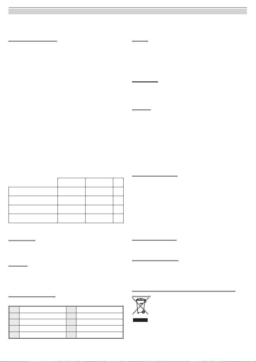
Basso/
Medio Basso
Medio Alto/
Alto
Livello Sonoro 60/70 80/90 dB
Solo Sirena 2,6 4,4 mA
Sirena e Lampeggiatore 0,5Hz 5,7 7,5 mA
Sirena e Lampeggiatore 1Hz 6,8 8,6 mA
Tab. 1 Corrente assorbita dal FC430LPSB e dal FC430LPASB.
INTRODUZIONE
La serie FC430LP di Avvisatori Acustici/Ottico-Acustici Indirizzabili Alimen-
tati da Loop, sono progettate per essere pilotate da una centrale FireClass
tramite il Loop indirizzabile.
Il tono, il volume e la frequenza del lampeggio si programmano tramite l'ap-
plicazione FireClass Console.
CARATTERISTICHE
La sirena ha quattro livelli sonori: ‘Alto’ (90dB ±3), ‘Medio Alto’ (80 ±3dB),
‘Medio Basso’ (70 ±3dB) o ‘Basso’ (60dB ±3).
Il lampeggiatore ha due frequenze di lampeggio: ‘Lampeggio Lento’ (1/2Hz)
o ‘Lampeggio Veloce’ (1Hz).
La serie FC430LP ha un isolatore di linea integrato.
IDENTIFICAZIONE DELLE PARTI
Vedere le figure 1, 2,3e5.
1Dispositivo di bloccaggio 6Passaggio cavi
2Sede del dispositivo di
bloccaggio 7Base ottico/acustica
3Porta di programmazione 8Rilevatore Fireclass
4Scatola elettrica 9Dispositivo di bloccaggio
5Flangia di montaggio
tipo A 10 Centrale Fireclass
CABLAGGIO
I cavi devono essere selezionati in conformità con il documento di progetta-
zione e nel rispetto delle norme applicabili.
La sezione massima del cavo collegabile ad ogni morsetto è di 2,5 mm2.La
sezione và calcolata in base alle caratteristiche del cavo e del carico.
I cavi devono essere collegati come mostrato in Fig. 5 rispettando la corretta polarità.
NOTE SUI COLLEGAMENTI
Osservare le seguenti note:
1) Tutti i collegamenti devono essere conformi alle norme applicabili.
2) Nessun conduttore deve essere collegato a terra.
MONTAGGIO
Installazione su una superficie piana tramite la flangia di montaggio tipo ‘A’.
Per installare una base FC430LP, procedere come di seguito:
1) Far passare i cavi del loop indirizzabile attraverso il foro di entrata cavi
della flangia di montaggio.
2) Fissare la flangia di montaggio ad una superfice piana.
3) Far passare i cavi del Loop indirizzabile attraverso il foro di entrata cavi della
base FC430LP, quindi agganciare la base alla flangia di montaggio.
4) Collegare la base FC430LP come mostrato in Fig. 5 rispettando la cor-
retta polarità.
5) Posizionare il dispositivo di bloccaggio (fornito) sulla base, premendolo
fino al suo completo bloccaggio. Vedere Fig. 3.
6) Posizionare l'aletta con l'ndirizzo sul rivelatore. Fissare il rivelatore alla
base acustica ( l'aletta con l'indirizzo sarà trasferita alla base acustica).
PROGRAMMAZIONE DELL' INDIRIZZO
L'indirizzo di fabbrica dei dispositivi FC430LP è 255, questo deve essere im-
postato all'indirizzo di loop del dispositivo tramite lo strumento per la pro-
grammazione dei dispositivi indirizzabili FC490ST. L'indirizzo della sirena
può essere programmato prima dell'installazione usando la porta di pro-
grammazione interna (vedere Fig.1 e 4).
+Nota: quando si collegano le basi FC430LP allo strumento per la pro-
grammazione dei dispositivi indirizzabili FC490ST, è possibile un ritardo
di 10 secondi prima che la comunicazione sia possibile.
+Nota: questo dispositivo impegna un solo indirizzo del loop.
+Nota: una volta programmato l'indirizzo, annotare la posizione del dispo-
sitivo e l'indirizzo, per segnarlo sul progetto dell'impianto.
INFORMAZIONI PER L'ORDINE
FC430LPSB: Base Acustica Indirizzabile Alimentata da Loop
FC430LPASB: Base Ottico/Acustica Indirizzabile Alimentata da Loop
INFORMAZIONI SUL RICICLAGGIO
Si consiglia ai clienti di smaltire i dispositivi usati (centrali, rilevatori, sirene,
accessori elettronici, ecc.) nel rispetto dell'ambiente. Metodi potenziali com-
prendono il riutilizzo di parti o di prodotti interi e il riciclaggiodi prodotti, com-
ponenti e/o materiali.
DIRETTIVA RIFIUTI DI APPARECCHIATURE ELETTRICHE ED
ELETTRONICHE (RAEE - WEEE)
Nell'Unione Europea, questa etichetta indica che questo pro-
dotto NON deve essere smaltito insieme ai rifiuti domestici.
Deve essere depositato in un impianto adeguato che sia in
grado di eseguire operazioni di recupero e riciclaggio.
Il costruttore si riserva il diritto di modificare le specifiche tecniche di questo
prodotto senza preavviso.
Istruzioni di Installazione Doc. versione 2.0 16 Marzo 2012 3
FireClass FC430LP Serie di Avvisatori Acustici/Ottico-Acustici Indirizzabili

120.515.053 Doc. version 2.0 Sheet 1 16.March 12 – Subject to change without notice. ISTISBL3FC430LPB 2.0 160312 V10
2
1
3
Fig. 1 FC-Meldersockel mit Sirene und Blinklicht – FC430LPASB.
FC430LPASB Sounder and Beacon Base.
Avvisatore Ottico/Acustico FC430LPASB.
D
O
N
O
T
P
A
I
N
4
5
6
8
7
Fig. 2 Einbau des FC-Meldersockels mit dem Aufputzsockel Typ A.
Fitting to a flat surface.
Montaggio su una superficie piana.
Fig. 4 FC490ST Programming Lead and FC430LP Programming Port Interface.
Connettore di Programmazione del FC490ST e Porta di Program-
mazione del FC430LP.
R
LL1
L2
M5B
5B
FC450IB
FC430LPSB/
FC430LPASB
–L1
+L1
+L1
–L1
LEFT
RIGHT
R
LL1
L2
MR
LL1
L2
M
R
LL1
L2
M
R
LL1
L2
M5B
10
Fig. 5 Anschlussschema.
Simplified Wiring Diagram.
Schema dei collegamenti semplificato.
9
Fig. 3 Setzen der optionalen Sperre.
Fitting Locking Device.
Dispositivo di Bloccaggio.
0786
Thorn Security Ltd
Dunhams Lane
Letchworth SG6 1BE
UK
10
0786-CPD-20899
EN54-3:2001 + A1:2002 + A2:2006
EN54-17:2005
FC430LPSB
FC430LPASB
Signalgeber mit integr. Kurzschlußisolator zur
Verwendung in Brandmeldeanlagen.
Sounder with integr. short circuit isolator for use in fire
detection and fire alarm systems.
Installation Instructions: 120.515.053
©FireClass
Via Gabbiano 22, Z. Ind. S. Scolastica
64013 Corropoli (TE), Italy
Hillcrest Business Park Cinderbank Dudley West Midlands
DY2 9AP United Kingdom
www.fireclass.co.uk
This manual suits for next models
4
Table of contents
Languages:
Other Tyco Marine Equipment manuals