Simpson Lawrence Pacific C1250 Guide

1
pacific
C12 50 CA PS TA N
C1250STD
in sta lla tio n, o per a tio n & m a in tena nce i ns tr u ct io n s
contents
..............................................................................................................................
sim ps o n -la w ren ce
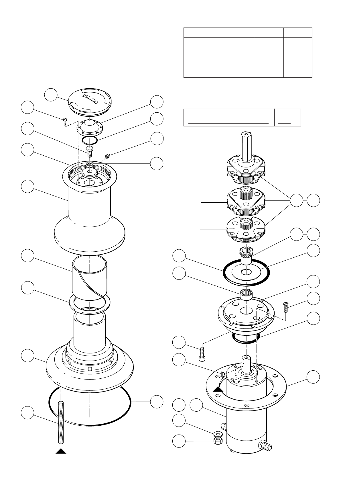
1.0 P AR T S
1.1 E xploded Diagram
1.2 F or F uture R eference
1.3 P arts List
2.0 P L ANNING THE INS T AL L A TION
2.1 P ackage C ontents
2.2 Additional R equirements
2.3 E lectric C able S election
3.0 AC C E S S OR IE S
4.0 S P E C IF IC ATION
4.1 P erformance Data
4.2 Materials
5.0 INS TAL L A TION
5.1 F itting C aps tan to Deck
5.2 Wiring
5.3 Test
5.4 P rotection of B elow Deck P arts
5.5 Wiring Diagrams
6.0 OP E R AT ING INS T R UC T IONS
6.1 S afety F irs t!
6.2 Hauling In
7.0 IMP O R T A NT US E R INF OR MA TION
8.0 MAINTE NA NC E
8.1 G eneral R ecommendations
8.2 Winter Laying Up
9.0 WA R R A NTY
SIM PSON
LAW RENCE

2
13
27
33
30
32
10
18
26
31
3
28
24a24
27a
26a
23
12
S tage 3
S tage 2
S tage 1
1.2.1 Identify your model
Type List No. Tick
12V P acific C1250 Anchoring 0032010
24V P acific C1250 Anchoring 0032020
1.2.2 P leas e note your serial number and voltage. (P rinted on motor
label). T his information is es sential when ordering spares.
V
1.0 P AR T S
1.1 E xploded Diagram
1.2.0 F or F uture R eferenc e
After you have read this instruction booklet, please keep it safe
on board your vess el for future reference.
9
11
4
2
6
5
7
15
22
16
8
17
19
25

3
1.3 PARTS LIST
Item Part No. Part Description Quantity
C1250 C1250
Anchoring Anchoring
2 P103064 Shim Bearing - Main 1
3 P103036 Shim Bearing - Gears 1
4 P103037 Shim W asher - Drum 1
5 P106003 Drum 1
6 P106200 Cap - T op 1
7 P106210 Cap - Inner Seal 1
8 P106215 Cap - Lock 1
9 P109003 Deck Housing 1
10 P109301 Deck Clamp 1
11 P154000 Stud 6
12 P339017 Nut 6
13 P342000 O Ring 1
15 P342050 O Ring 1
16 P342435 O Ring 1
17 P354101 Screw 6
18 P354014 Screw 6
19 P354231 Screw 1
22 P366042 Washer 1
23 P366045 Washer 6
24 P418201 Gearset (Complete) 1
24a - Gearset (Complete) -
25 P418100 Grease Nipple 1
26 P336040HMS Motor 12V 1
26a P336041HMS Motor 24V 1
27 P118012 Pinion 1
27a - Pinion -
28 P303104 Spragg Clutch 1
30 P354325 Screw 4
31 P113020 Key 1
32 P342030 O Ring 1
33 P136007 Flange 1

4
2.0 PLANNING THE INSTALLATION
2.1 Package Contents
Capstan
Mounting Studs, Washers, Nuts & 'O' Ring
Clamping Plate
Mounting Template
Safety Instructions
Installation Warning Label
Instruction Manual
2.2 Additional Requirements
Each capstan installation requires :
a. A solenoid for a single direction installation. (Unless the
High Load Foot Switch only is used)
b. A control switch (or switches) by preference.
c. A breaker/isolator for overload protection which can also be
used as a main isolating switch. (Simpson-Lawrence
recommend the breaker/isolators listed under 3.0
Accessories)
d. The following tools:
Capstan Installation
Flat Blade Screwdriver
10mm (3/8") Diameter Drill
13mm A/F (1/2") Spanner (Wrench)
Jig Saw or Trepanning Tool
Wiring Installation
Flat Blade Screwdriver
Crimping Pliers / Wire Stripper
13mm A/F (1/2") Spanner or Socket
8mm A/F (5/16") Spanner or Socket
e. Marine grade silicone sealant. DO NOT use permanent
adhesive/sealant.
f. Suitable electrical cable and crimp terminals.
2.3 Electric Cable Selection
To achieve the best performance and safeguard your electrical
system, it is essential that any electric capstan is fitted with
sufficiently large diameter cable to cope with the current draw
imposed upon it and, to keep the voltage drop within acceptable
limits. In any circumstance, voltage drop due entirely to cable
resistance should not exceed 5%, roughly 0·5V for a 12V
installation and 1·0V for a 24V one.
The following tables give recommended cable sizes. The
recommendations are based on the total length of cable
required, from the battery to the capstan and back to the
battery, following the route of the cables. (See the Wiring
Diagram for the definition.)
DO NOT confuse Cable Length with the length of the vessel!
3.0 ACCESSORIES
Item List Number
Breaker/Isolator (70 Amp) 12V Installation 0050711
Breaker/Isolator (50 Amp) 24V Installation 0050710
12 Volt Solenoid Single direction 0052505
24 Volt Solenoid Single direction 0052506
Foot Switch Single direction 0052514
High Load Foot Switch Single direction 0052516
USA list number for above (Black) LEWP49C
USA list number for above (White) LEWP49CW
METRIC or STARTER CABLE
Voltage Cable Length Size
m(ft.) (mm²)
18.0m (60ft.) 25
12 27.0m (90ft.) 35
37.0m (120ft.) 50
18.0m (60ft.) 6
24 27.0m (90ft.) 10
37.0m (120ft.) 16
AMERICAN CABLE
Voltage Cable Length Size
m (ft.) (AWG)
18.0m (60ft.) 2
12 27.0m (90ft.) 1
37.0m (120ft.) 1/0
18.0m (60ft.) 8
24 27.0m (90ft.) 8
37.0m (120ft.) 6
Thin wire of 1·5mm² cross sectional area, 21/0·30 PVC covered
(American equivalent 14 AWG) is required for the control switch
circuits. This is used to connect the switch(es) to the
solenoid(s).

5
8.2
5.1.6 Longer Studs
For thicker than standard decks, simply fit longer studs as
appropriate (Thread M8 x 1.25). Studs to special lengths may
be obtained from Simpson-Lawrence Engineering Limited.
5.2.0 Wiring
5.2.1 General Recommendations
Warning! Carefully check to ensure that the capstan motor is
wired to correct polarity. It is possible to damage the gearbox
if the motor is wired to the wrong polarity.
The wiring system should be of the two cable fully insulated
return type, which avoids possible electrolytic corrosion
problems. Most modern installations are negative return
(negative earth) but polarity should be checked.
Solenoids should be mounted as close to the battery as
possible, in a dry location using the mounting holes provided.
Under no circumstances should solenoids or solenoid control
boxes be installed in chain lockers or similar damp or semi
exposed areas.
Overload protection must be built into the capstan wiring
circuit. This protects the wiring and prevents undue damage to
the capstan motor, in the event of it being stalled by an
excessive load in service. It is advisable to site the Breaker/
Isolator in a dry, readily accessible place, as it must be
manually reset should an overload occur that causes it to trip
to the OFF position.
If you are NOT using the Breaker/Isolator recommended, an
alternative MUST have identical characteristics.
NB: Crimp terminals should be used on all wire ends for good
electrical connections.
5.2.2 Control Switch Installation
Follow the mounting instructions supplied with the switch.
Remember when using more than one control switch, it is
important to their correct operation, that they are wired in a
parallel circuit.
5.3 Test
Immediately after installation, it is recommended that the
capstan is tested to ensure it functions correctly in all modes,
e.g., forward, reverse and manual operations should be tested.
5.4 Protection of Below Deck Parts
Check all terminals or connections are firmly secured. Coat
ALL below deck surfaces, including the terminals, with rubber
or plastic type paint (automotive underseal is one convenient
way) OR wrap completely in self amalgamating tape OR coat/
protect in a similar way with some other system suitable for a
marine environment.
4.0 SPECIFICATION
4.1 Performance Data:
Typical Working Figures (12V/24V) Warping
Load Speed Current Draw
110kg(220lb) 8.0m(26ft)/min 80 Amp - 12V
110kg(220lb) 8.0m(26ft)/min 40 Amp - 24V
Typical Working Figures (12V/24V) Anchoring
Load Speed Current Draw
110kg(220lb) 18.0m(59ft)/min 80 Amp -12V
110kg(220lb) 18.0m(59ft)/min 40 Amp - 24V
Motor 4 Pole Permanent Magnet
Weight 10kg (22lb)
5.0 INSTALLATION
5.1.0 Fitting Capstan To Deck
5.1.1 Preparation
The capstan must always be mounted vertically. DO NOT
mount capstan in a horizontal direction as oil will leak from the
gearbox and the capstan will wear out prematurely. If the deck
top is uneven a suitable mounting pad may be required to take
up camber or sheer. Decks which are thin, of foam or balsa
laminate construction, will require a backing piece in order to
spread the load which will be applied locally to the deck while
the capstan is in use. Care must be taken if the deck is of
uneven thickness and a mounting pad and/or backing piece
fitted that the top and bottom surfaces are parallel for optimum
clamping.
5.1.2 Position of Capstan
Select a site for the capstan on the deck that is a comfortable
position for the operator to tail rope off the drum and preferably
feed rope straight into the storage area. A position for the
switch should be found that makes it accessible to the capstan
operator’s foot or knee.
5.1.3 Access
Allow for access to the top of the drum during maintenance.
5.1.4 Mounting Template
Place the mounting template in the desired position. Drill a
clearance hole for the motor to pass through as detailed and
six 10mm (3/8") holes for the studs. The studs supplied suit
decks and mounting pads up to 75mm (3") thickness.
5.1.5 Fitting
Place the capstan and studs through the holes in the deck,
when satisfied that all is correct, fit any packing, the clamping
ring, the nuts and washers, and tighten evenly and firmly using
a 150mm (6") long spanner.

6
A
D
CB
+
+
Circuit Breaker/Isolator
70A-0050711-12v
50A-0050710-24v
12v/24v
BATTERY
High Load Foot Switch
0052516
C1250 CAPSTAN
Total Length Required = A + B + C + D
WIRE FROM TO
Thick cable Positive battery terminal Breaker/Isolator
Thick cable Breaker/Isolator High Load Foot Switch
Thick cable High load foot switch Capstan positive terminal
Thick cable Negative battery terminal Capstan negative terminal
5.5.0 Wiring Diagrams
5.5.1 Single Direction Wiring (High Load Foot Switch Only)
Note: Reversing polarity will result in permanent damage to the capstan (see 5.2.1). ALL installations must be carried out in accordance with
USCG, ABYC and NMMA requirements. If you have any questions regarding this installation contact nearest Simpson-Lawrence Agent.

7
+
A
Circuit Breaker/Isolator
70A-0050711-12v
50A-0050710-24v
12v/24v
BATTERY
Single Direction Solenoid
0052505-12v
0052506-24v
B
Inline Fuse
12v-5 AMP, 24v-3.15 AMP
Deck Foot Switch
0052514
QU900/D
QU900/U
D
C
High Load Foot Switch
0052516
LEWP49C
LEWP49CW
+
C1250 CAPSTAN
Total Length Required = A + B + C + D
Only one type of switch is required, though more than one may be fitted.
5.5.2 Single Direction Wiring
WIRE FROM TO
Thick cable Positive battery terminal Breaker/Isolator
Thick cable Breaker/Isolator Solenoid
Thick cable Solenoid Capstan positive terminal
Thick cable Negative battery terminal Capstan negative terminal
Thin wire Solenoid Control switch(es)
Thin wire Control switch(es) Main circuit (positive)
Thin wire Solenoid Main circuit (negative)
Warning!: If you are not sure that you understand the above guidelines seek professional advice. NB: Use a minimum wire gauge of
1.5mm² (14 AWG) to connect switches.
Note: Reversing polarity will result in permanent damage to the capstan (see 5.2.1). ALL installations must be carried out in accordance with
USCG, ABYC and NMMA requirements. If you have any questions regarding this installation contact nearest Simpson-Lawrence Agent.

8
6.0 OPERATING INSTRUCTIONS
6.1 Safety First!
Your Simpson-Lawrence Pacific capstan is a powerful piece of
equipment and should be respected as such. Keep young
children and observers, who are unfamiliar with anchoring
procedures, away from the operating area when in use. To
avoid personal injury, ensure that fingers, limbs and clothing are
kept clear of the rode and windlass during operation. Always
ensure there are no swimmers nearby when dropping your
anchor.
Always keep the Isolator switch OFF except when in use.
6.2.0 Hauling In
6.2.1 Warping
Anchor warp should be laid onto the drum, two or three turns in
a clockwise direction. The operator should stand (or kneel) in a
comfortable position to activate the deck switch whilst tailing the
warp behind and into the storage area, if possible.
6.2.2 Apply Tension
Apply a light even tension to the warp before activating the
switch. If very heavy pulls are necessary apply power in short
bursts of about 10 seconds duration. The speed of hauling
depends on the load on the anchor and will increase after the
anchor breaks free.
6.2.3 Caution!
Should the capstan stall, switch off and wait a few seconds
before trying again. If the recommended breaker/isolator has
tripped, it will require to be manually reset before the capstan
can operate again. It is important to the future, good
performance of the capstan's motor that the capstan is not
allowed to stall for more than a few seconds and therefore,
sensible to avoid stalling your capstan whenever possible.
6.2.4 Recovery
On retrieval, always remember to secure your anchor
independently of the capstan so as to prevent accidental
launch when under way.
6.2.5 Caution!
Chain may be run over the capstan if necessary but marking of
the drum will occur.
6.2.6 Power off
Turn the power isolator OFF after use.
6.2.7 Warning!
Serious damage can be caused by incorrect assembly and
your guarantee may be invalidated as a result. Always
proceed with care. The Pacific family of capstans have been
designed for ease of installation and removal. It should not,
therefore, be necessary to remove any parts other than the
deck clamping ring, nuts and washers.

9
7.0 IMPORTANT USER INFORMATION
Classification Societies require that a vessel lying to anchor
should have its rode held by a chain stopper or equivalent
strong point as capstans are not designed to withstand the
loads generated under storm conditions. This rule should be
applied to all craft!
At all times it is the responsibility of the boat user to ensure
that the anchor and rode are properly stowed for the prevailing
sea conditions. This is particularly important with high speed
power boats as an anchor accidentally falling into the water
whilst under way can cause considerable damage.
An anchor capstan is mounted in the most exposed position on
a vessel and is thus subject to severe atmospheric attack
resulting in a possibility of corrosion in excess of that
experienced with most other items of deck equipment.
As the capstan may only be used infrequently, the risk of
corrosion is further increased.
When the windlass is mounted in an anchor well with a closing
lid, due to lack of ventilation and consequent high saline
conditions the rate of corrosion is accelerated. It is essential
that the capstan is regularly examined, operated and given any
necessary maintenance. This is of even greater importance
when the capstan is installed in an anchor well!
8.0 MAINTENANCE
8.1 General Recommendations
Isolate the capstan electrically, before carrying out any
maintenance work. After the first two or three anchor
recoveries, check that the capstan is still fastened tightly to the
deck as it should now be bedded-in.
Every three months, unscrew the drum cap top (Part no. 6)
using a broad bladed tool. As the cap may be stiff, a good fit in
the slot is advised to avoid damage to the cap. Apply two
shots of grease to the grease nipple under the top cap. A
smear of grease around the seat area of the top cap will ease
future removal.
Regularly wash down the above deck parts of your capstan
with fresh water.
Ensure that all below deck parts are kept dry. The gears and
gearbox bearings have been lubricated for you and require no
regular attention. It is recommend that the gearbox and motor
exteriors are regularly treated with a water repellent spray
when mounted exposed within a chain locker.
Examine all electrical connections for possible corrosion.
Clean and lightly grease as necessary.
8.2.1 Winter Laying Up
As with all items of marine equipment poor installation or
neglect is often responsible for damage caused during the
winter lay up period. Given correct installation and
maintenance your capstan will require little attention prior to, or
after, winter lay up. Check between the deck plate and deck
for signs of water ingress. Should it occur, remove, clean and
reseal the deck plate. If necessary, replace 'O' ring seal.

10
9.0 THREE YEAR LIMITED WARRANTY
WARRANTY COVERAGE: SIMPSON-LAWRENCE LIMITED., warrants to the original purchaser, subject to the limitations
and exclusions described below, that this product will be free from defects, in material and workmanship under normal use
and service, for a period of three (3) years from the date of its original sale, except that the warranty shall be for a period of
one (1) year for seals, electric motors, electrical equipment, electronic controls, composite gipsies and hydraulic pumps.
Simpson-Lawrence will repair or replace any part which proves to be defective in normal use during the period of the
warranty.
WARRANTY CLAIMS PROCEDURES: If a defect is discovered during the applicable warranty period, Buyer must
promptly notify Simpson-Lawrence of such, in writing, at the nearer address below, providing proof of purchase. For
warranty service, the product must be returned to Simpson-Lawrence for examination. This examination will be performed
by Simpson-Lawrence at no charge to Buyer. Buyer is responsible for any labour costs associated with preparing the
product or parts for shipping and the cost of shipping or transporting the product or parts to and from Simpson-Lawrence.
REMEDY: Simpson-Lawrence will repair any defect in material or workmanship or, at it’s option, correct such defect by
replacing non-conforming goods or parts. Such repairs and/or new parts are warranted for the unexpired portion of the
original warranty, or for 90 days, whichever is later. Warranty work (parts and/or Labour) shall be at Simpson-Lawrence’s
expense; however, product preparation and shipping costs to or from Simpson-Lawrence shall be borne by Buyer. These
remedies are the Buyer’s exclusive remedies for breach of warranty.
LIMITATIONS AND EXCLUSIONS: (1) This warranty applies only if the product is used under non-commercial, normal
use in service, and shall not apply to (a) products subjected to (i) conditions or usage that exceed the product’s
performance specifications, (ii) incorrect maintenance, or (iii) use in applications for which they are not intended; (b)
defects or damage caused by a force majeure which exceed design specifications, including but not limited to, wear and
tear, corrosion or ultraviolet degradation; and (c) defects or damages caused by unauthorized attachments, accessories or
modifications. (2) Simpson-Lawrence’s warranties of fitness and merchantability, as well as other expressed warranties
contained herein, shall apply only to those parts and components manufactured by Simpson-Lawrence, which were
installed by Simpson-Lawrence or other authorized personnel, and shall not be effective or actionable if any warranty
repair or replacement work is performed by any unauthorized party. Simpson-Lawrence reserve the right to alter the
products specifications and design without prior notice.
THE FOREGOING WARRANTIES ARE EXCLUSIVE AND IN LIEU OF ALL OTHER EXPRESSED WARRANTIES.
IMPLIED WARRANTIES, INCLUDING BUT NOT LIMITED TO THE IMPLIED WARRANTIES OF MERCHANTABILITY
AND FITNESS FOR A PARTICULAR PURPOSE, DO NOT EXTEND BEYOND THE DURATION OF THE EXPRESSED
WARRANTIES PROVIDED HEREIN.
IN NO CASE SHALL SIMPSON-LAWRENCE BE LIABLE FOR ANY SPECIAL, INCIDENTAL OR CONSEQUENTIAL
DAMAGES BASED UPON BREACH OF WARRANTY, BREACH OF CONTRACT, NEGLIGENCE, STRICT TORT OR
ANY OTHER LEGAL THEORY. THIS LIMITATION DOES NOT APPLY TO CLAIMS FOR PERSONAL INJURY.
SOME STATES, OR COUNTRIES, DO NOT ALLOW THE EXCLUSION OR LIMITATION OF INCIDENTAL OR
CONSEQUENTIAL DAMAGES OR LIMITATIONS ON HOW LONG AN IMPLIED WARRANTY LASTS, SO THE ABOVE
LIMITATIONS OR EXCLUSIONS MAY NOT APPLY TO YOU.
THIS WARRANTY GIVES YOU SPECIFIC LEGAL RIGHTS AND YOU MAY ALSO HAVE OTHER RIGHTS WHICH
VARY FROM STATE TO STATE, OR COUNTRY TO COUNTRY.

11
The model described in this document is subject to a policy of continual improvement. Simpson-Lawrence Engineering Limited
reserve the right to alter specifications and recommendations without notice. For the latest information regarding any aspect of your
windlass please contact your local agent or Simpson-Lawrence Engineering Limited:-

12
Simpson-Lawrence Engineering Limited Deanside Road
Hillington
GLASGOW
G52 4SZ
United Kingdom.
Telephone : +44 (0)141 304 8000
Facsimile : +44 (0)141 304 8001
Customer Support Telephone : +44 (0)141 304 8025
Facsimile : +44 (0)141 304 8001
Simpson-Lawrence Limited 218/228
Edmiston
Drive
Ibrox
GLASGOW
G51
2YT
United
Kingdom.
Telephone : +44 (0)141 300 9100
Facsimile : +44 (0)141 427 5419
Service Division Telephone : +44 (0)141 300 9200
: +44 (0)141 427 9666
Facsimile : +44 (0)141 427 5419
Simpson Lawrence USA Inc. 6208, 28th Street East
Bradenton
FLORIDA
34203-4123
United States of America.
Telephone : 1 800
WINDLAS
: (Toll Free) 1 800 946 3527
: +1 941 753 7533
Facsimile : +1 941 746 7166
James Nilsson Limited 69 Hillside Road
Glenfield
AUCKLAND 10
New Zealand.
Telephone : +64 9 444 5219
: 0800 4 WINCH
: (Freephone) 0800 494 624
Facsimile : +64 9 444 5222
Copyright © Simpson-Lawrence Engineering Limited. All Rights Reserved. 3201-200 (D1065-1)
SIMPSON
LAWRENCE
Table of contents
Other Simpson Lawrence Marine Equipment manuals