800 SERIES
17A-03-AV
2 11/08
PAGE 2 of 4
2. INTRODUCTION
The AV Series of Loop Powered Addressable Sounder/
Sounder-Beacons are designed to be driven from an MX/ZX
controller via the addressable loop.
Tone, volume and flash rates are set in Consys.
3. FEATURES
The sounder has four volume settings ‘High’ (90dB ±3), ‘Mid
High’ (80 ±3dB), ‘Mid Low’ (70 ±3dB)or ‘Low’ (60dB ±3).
The beacon has two flash rates ‘Slow Flash’ (1/2Hz) or ‘Fast
Flash’ (1Hz).
The AV Series have a built-in line isolator.
4. CABLING
Cables are to be selected in accordance with Publication 17A-
02-D and the requirements of the current issue of BS5839.
Cabling should be connected as shown in Fig. 4 ensuring
correct polarity.
5. WIRING NOTES
The following notes apply:
a) All wiring must conform to the current edition
of IEE Wiring Regulations and BS 5839 Part 1.
b) All wiring must be free of earths.
6. MOUNTING
6.1 INSTALLATION TO A FLAT SURFACE
USING TYPE ‘A’ MOUNTING FLANGE
THIS MOUNTING
FLANGE IS
SUPPLIED
WITH THE BASE
SOUNDER
BASE
CABLE
ENTRY
D
O
N
O
T
P
A
I
N
T
DETECTOR
ELECTRICAL
BACKBOX
SOUNDER
BLANKING CAP
OPTION
(WHEN DETECTOR
NOT FITTED)
Fig. 2 Fitting to a Flat Surface
To install an AV base, proceed as follows:
a) Feed the addressable loop wiring through
the mounting flange cable entry.
c) Secure the mounting flange to a flat surface.
d) Feed the addressable loop wiring through
the AV base cable entry, then clip the
sounder base to the mounting flange.
e) Wire the AV base as shown in Fig. 7
ensuring correct polarity.
f) Fit the locking device (supplied) to the
base, pressing it in until it is fully
seated. See Fig. 4.
g) Fit the address flag to the detector. Fit the
detector to the sounder base, (the address
flag will be transferred to the sounder base).
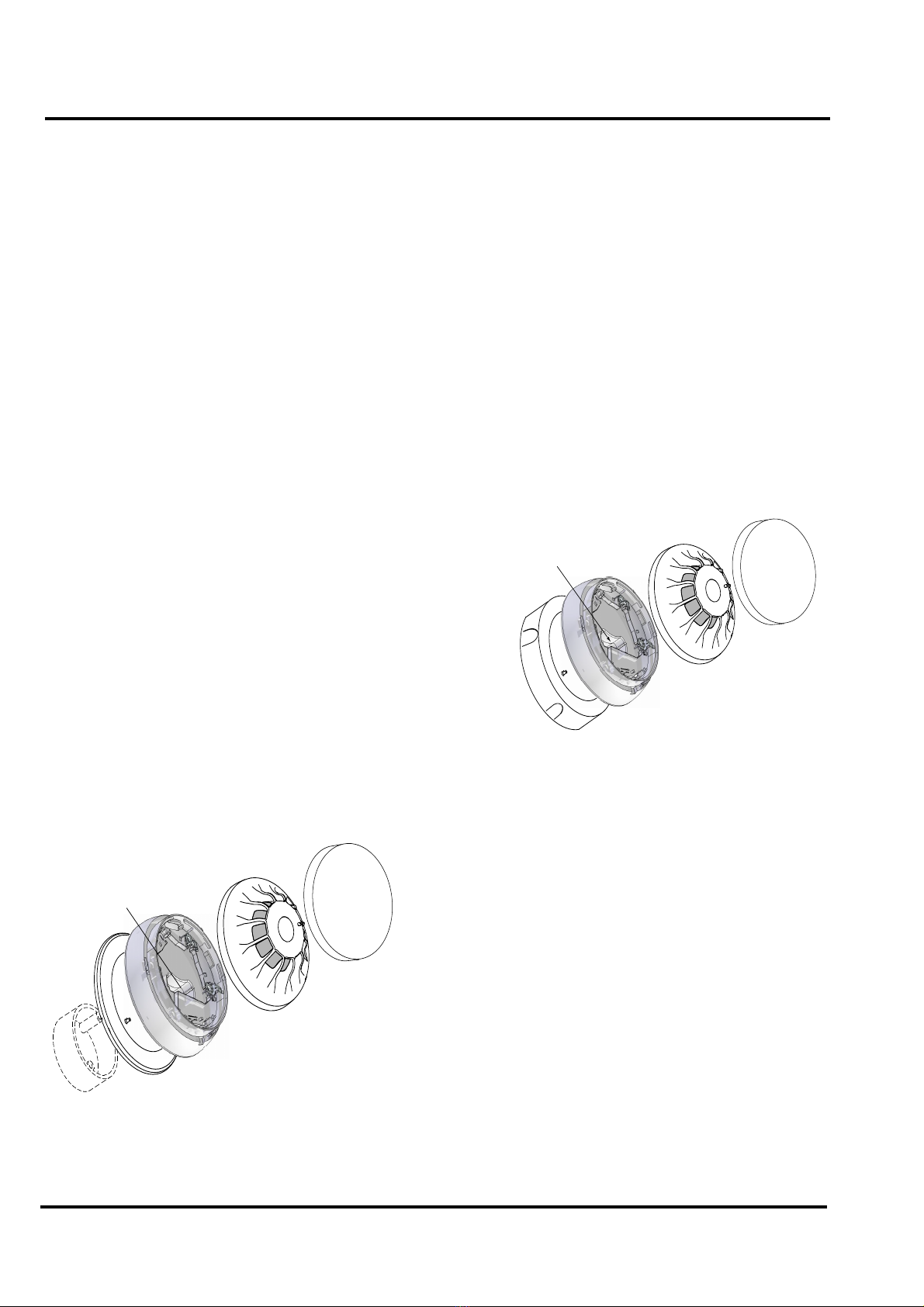
INSTALLATION TO A FLAT SURFACE
USING DAB3-4 MOUNTING FLANGE
To install an AV base, proceed as follows:
a) Remove the required number of conduit
knockouts.
b) Fit the conduit, feed the cables through the
conduit and the cable entry hole of the
mounting flange.
c) Fit the mounting flange to the conduit and
secure with suitable screws.
d) Clip the AV base to the mounting flange.
e) Wire the AV base as shown in Fig. 7
ensuring correct polarity.
f) Fit the locking device (supplied) to the
base, pressing it in until it is fully
seated. See Fig. 4.
g) Fit the address flag to the detector. Fit the
detector to the sounder base, (the address
flag will be transferred to the sounder base).
THE DAB3-4
MOUNTING
FLANGE
MUST BE
ORDERED
SEPARATELY
SOUNDER BEACON
BASE
CABLE
ENTRY
D
O
N
O
T
P
A
I
N
T
DETECTOR
SOUNDER
BLANKING CAP
OPTION
(WHEN DETECTOR
NOT FITTED)
Fig. 3 Fitting Using Conduit


