LED INDICATOR STATUS MESSAGES
The LED indicator’s messages are used only during installation and servicing.
LED indicator is inactive when the battery cover is in place for saving up battery charge (and due to the fact that normally the LED is hidden by
the detector or the cover plate).
POWERING UP AND LINKING - PRELIMINARY NOTES
TW-BS-01, TW-BSB-23W-01 and TW-BSB-23R-01 need to be powered up with the supplied batteries.
Linking is the operation through which these devices are “wirelessly connected” to a TW-MTI-01, TW-MEC-01 or TW-ME-01 Taurus network
device.
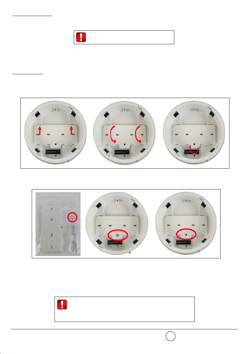
POWERING UP - FIRST TIME USE
Use this procedure the first time you power up a TW-BS-01, TW-BSB-23W-01 or TW-BSB-23R-01.
1) Make sure the Link / program switch is set on “ON”.
2) Insert the two supplied batteries into their device’s lodgments.
Ensure that the batteries are installed properly, with their polarities matching the indications on the device.
POWERING UP - DEVICE LINKED TO THE SYSTEM
Use this procedure when a TW-BS-01, TW-BSB-23W-01 or TW-BSB-23R-01 is successfully linked to its Taurus system and you have to
extract one or both batteries (e.g. batteries substitution).
1) Reinsert the battery or both batteries into their lodgments.
Do not touch the Link / program switch.
If performing a batteries substitution, use two brand new batteries and substitute both of them.
Ensure that the batteries are installed properly, with their polarities matching the indications on the device.
POWERING UP - RECOVERY
Use this procedure when you fail to link successfully a TW-BS-01, TW-BSB-23W-01 or TW-BSB-23R-01 or you want to link it again.
1) Move alternatively the Link / program switch 5 times.
2) Set the Link / program switch on “ON”.
3) Insert the two supplied batteries into their device’s lodgments.
Ensure that the batteries are installed properly, with their polarities matching the indications on the device.
With the battery cover installed, the LED indicator
remains inactive.
Table 1
www.argussecurity.itARGUS SECURITY S.R.L. - Via del Canneto, 14 - 34015 - Muggia (TS) - Italy 6
Device status LEDs indication
Power up (DIP on “ON”) Blinks red 4 times
Power up (DIP opposite “ON”) Blinks green 4 times
Entering wake-up mode Blinks alternatively green / red 4 times
Link success (one-by-one) Blinks green 4 times, then the same pattern again
Link failure (one-by-one) Enters wake-up mode and signals “Entering wake-up mode” following this failure
Link success (wake-up) Blinks green 4 times, then same pattern again
Link failure (wake-up) Blinks green 4 times, then blinks red on once, then blinks alternatively green / red 4 times
Normal condition LED off (can be programmed so as to blink green every wireless communication)
Alarm activation Blinks red every 2 seconds
Battery fault LED off (can be programmed so as to blink amber every 5 seconds)
Tamper fault LED off
Replaced Blinks amber 2 times