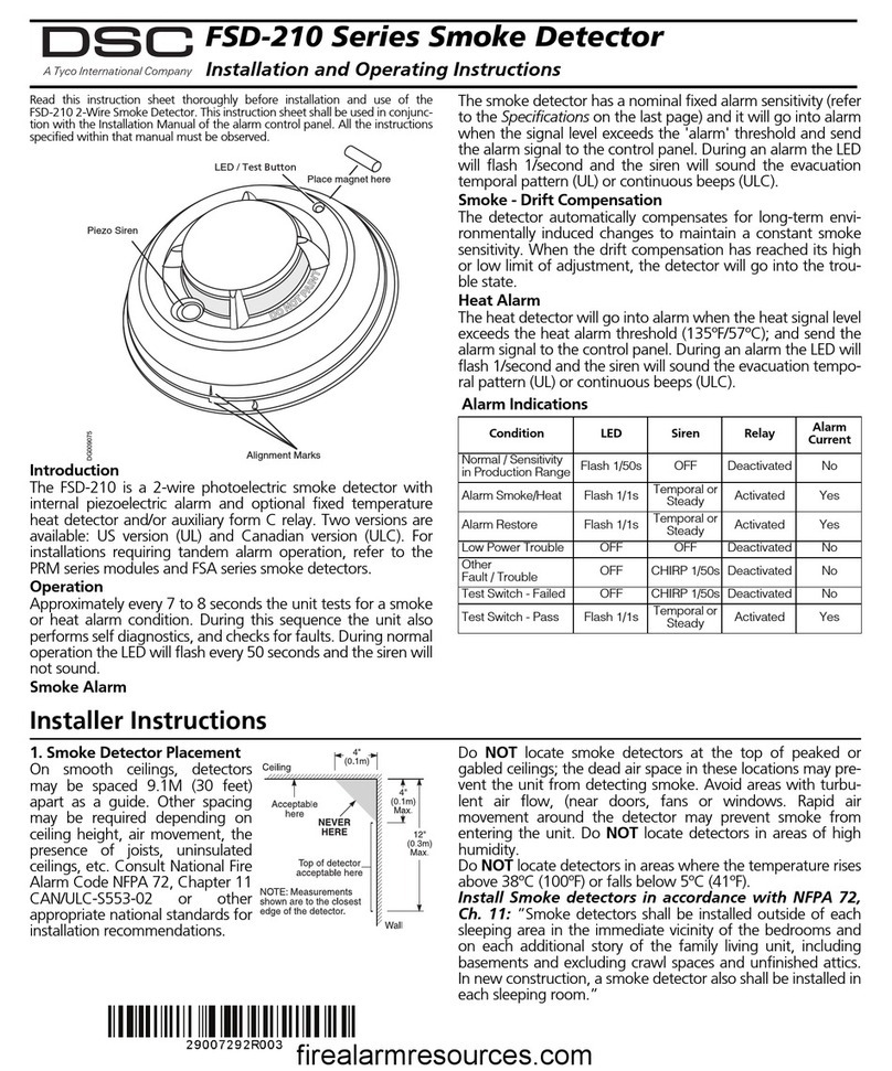
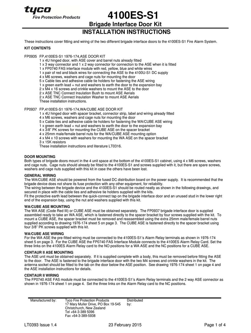
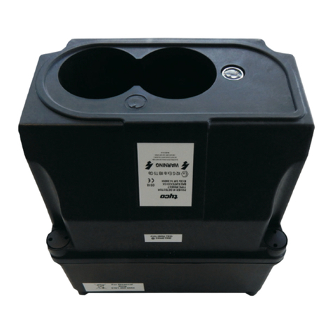
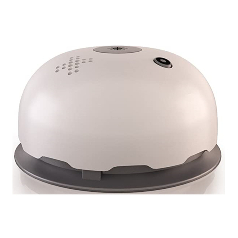
Tyco Visonic SMD-429 PG2 Series User manual

D-307866
SMD-429 PG2 Series Wireless Smoke
and Heat Detector
Installation and Operating Instructions
Read this instruction sheet thoroughly before installation and use of the SMD-429 PG2
Introduction
The SMD-429 PG2 is a wireless photoelectric smoke and heat detector with a fixed temperature
and rate of rise heat detector, and an internal piezoelectric alarm.
Three versions are available: a 915 MHz for US version (UL) and Canadian version (ULC), a
433 MHz and 868 MHz for International version (EU) and a 433 MHz for Australian version
(AUS).
Compatible Devices
The smoke detector is compatible with Visonic Control Panels and Power G receivers.
NOTE: For UL listed installations use only in conjunction with UL listed control panels: Power-
Master-10 and PowerMaster-30 PG2.
HUSH/TEST BUTTON
Operation
Approximately every 7 to 8 seconds the unit tests for a smoke or heat alarm condition. During
this sequence the unit also performs self diagnostics, and checks for tampers and faults. During
normal operation the green LED flashes every 60 seconds and the sounder does not sound.
Smoke Alarm
The smoke detector alarms when the signal level exceeds the “alarm” threshold and auto-
matically restores when the signal level falls below the alarm “restore” threshold. During an
alarm the red LED flashes once per second and the sounder sounds the evacuation temporal
pattern.
Alarm Silencing
This smoke alarm is provided with an automatically resettable alarm silencing feature. When the
sensor is in alarm, press the Test/Silence/Reset button to silence the local annunciation of the
alarm and transmit an alarm restore event to the control panel. The red LED flashes once per
second for up to 7 minutes, to indicate the alarm has been silenced.
After an alarm the red LED will flash once every 4 seconds to indicate an alarm in memory. The
alarm silence feature has a fixed time setting that desensitizes the smoke alarm for 7 minutes.
Alarm silencing does not disable the smoke alarm but rather reduces its smoke sensitivity. Fol-
lowing the silenced period the smoke alarm restores automatically to its intended operation. If
smoke around the unit is dense enough to suggest a potentially dangerous situation, it remains
in alarm, or may return to the alarm state quickly.
Detector Trouble
When the detector has a general fault, the yellow LED blinks once every four seconds and
there is a chirp every 48 seconds. After 4 hours, the panel will display a fire trouble message.
Detector and Status Indication

Status LEDs Sounder
Normal Green flash every 60 seconds Off
Heat Alarm Red flash every 1 second ANSI S3.41 temporal 3
Heat Test Red flash every 1 second ANSI S3.41 temporal 3
Smoke Alarm Red flash every 1 second
ANSI S3.41 temporal 3
(press button to hush for 5-10
minutes)
Smoke Test
(with canned
smoke) Red flash every 1 second
ANSI S3.41 temporal 3
(press button to hush for 5-10
minutes)
Test Alarm
(button press) Red flash every 1 second ANSI S3.41 temporal 3
Detector
Trouble Yellow flash every 4 seconds One chirp every 48 seconds
Low Battery Yellow flash every 12 seconds One chirp every 48 seconds
(press button to hush for 12 hours)
Detector Dirty Yellow flash every 8 seconds One chirp every 48 seconds
Power-up Red, yellow, green, flash sequence One chirp at the end of the power-
up sequence
Tamper Red, yellow, green flash sequence every
12 seconds Off
Hush Mode
Red flash every 1 second (alarm hush) Off
Yellow flash every 12 seconds (low
battery hush) Off
Detector Cleaning Required
When the detector is contaminated, the yellow LED blinks once every 8 seconds and there is a
chirp every 48 seconds. Refer to the MAINTENANCE section for cleaning the detector. After 4
hours, the panel displays a message fire clean.
Heat Alarm
The heat detector (cULus versions only) alarms when the heat signal level exceeds the heat
alarm threshold (135 ºF / 58 ºC); and will automatically restore when the heat signal level falls
below the heat alarm threshold (restore). The detector also goes into a heat alarm state when
there is a rapid increase in the temperature over a short period of time. During an alarm the
LED flashes 1/second and the sounder sounds the evacuation temporal pattern.
Tamper
The removal of the detector from the mounting plate initiates a “tamper” transmission. The
tamper condition is restored after the detector is mounted on the plate.
Wireless Transmissions
A supervisory message is transmitted at 128 second intervals for the SMD-429 PG2. If the sig-
nal is not received the control panel determines that the detector is missing.
The detector transmits the following:
lAlarm / Alarm Restore - (heat or smoke alarm). Transmitted at time of occurrence.
NOTE: During an alarm condition, the detector sends an alarm event to the control panel.
When the condition is restored, the detector sends an alarm restore event to the
panel and sets the alarm restore indicator. The red LED blinks once every 4
seconds until the Alarm in memory is cleared. You can clear the alarm restore indic-
ator from the control panel, or press and hold the test button for 5 seconds.
lTamper / Tamper Restore - (tamper switch activated) 10 second maximum delay on restore
before transmission.
lLow Battery - (battery voltage falls below threshold). Battery voltage is tested & transmitted
at the time of a supervisory or other transmissions.
lTrouble - (detector fault or sensor compensation limit reached). Troubles are transmitted at
the time of occurrence (one trouble per supervisory interval).
Batteries
The wireless smoke heat alarm is powered by 3 AAA Duracell Procell PC2400 or 3 AAA Ener-
gizer E92 batteries (included). The detector regularly checks for a low battery. If a low battery is
detected, the transmitter sends a low battery message to the control panel, which displays the
detector's ID at low battery. In addition, the yellow LED of the detector blinks every 12 seconds.
The detector's sounder chirps every 48 seconds and the yellow LED continues to blink until the
batteries are replaced. Pressing the hush button silences the chirps for 12 hours, if no other
trouble conditions exist. The batteries should be replaced with new batteries when the chirps
begin.

At low battery, the test button is disabled. An alternative test method is to use an aerosol test
gas such as ‘Solo A10 smoke detector tester’. Shake the can well, aim it at the smoke detector
and spray a short burst (no more than 1 sec) at the detector. If the alarm does not sound,
repeat every 10 seconds until alarm sounds or for a maximum of 1 minute.
NOTE: If the alarm does not sound, contact the installer or dealer for service.
Battery Installation and Replacement
CAUTION: Risk of explosion if battery is replaced by an incorrect type. Dispose of used bat-
tery according to the manufacturer's instructions.
To replace batteries, complete the following steps:
1. Remove the detector from its mounting base by twisting the detector counterclockwise.
Carefully remove batteries by lifting from the “+” end using a flathead screwdriver and dis-
pose of them according to local regulations.
2. To ensure a proper power-down sequence, wait a minimum of 30 seconds before
installing new batteries.
3. Install 3 new AAA batteries, available from a local Duracell or Energizer dealer in the bat-
tery compartment. Install the batteries by inserting the “-” end first, then pushing the “+”
end down. If the batteries are incorrectly inserted, please remove them carefully by lifting
them out from the “+” end and correctly re-inserting them.
BATTERY COMPARTMENT
+++
4. Re-install the detector on its mounting base by turning the detector clockwise until the mat-
ing marks align.
5. After the power-up sequence, the green LED should blink once every 60 seconds to indic-
ate normal operation. If the batteries are not installed correctly, the detector will not oper-
ate and the batteries may be damaged. If the detector does not power up, check that the
batteries are installed correctly and fully charged.
6. Test the detector as described later.
CONSTANT EXPOSURES TO HIGH OR LOW TEMPERATURES OR HIGH HUMIDITY MAY
REDUCE BATTERY LIFE.
Installation Instructions
The SMD-429 PG2 Series wireless smoke detector shall be installed and used within an envir-
onment that provides the pollution degree max 2 and over voltages category II in non-haz-
ardous locations, indoor only. The equipment is designed to be installed by SERVICE
PERSONS only; (SERVICE PERSON is defined as a person having the appropriate technical
training and experience necessary to be aware of hazards to which that person may be
exposed in performing a task and of measures to minimize the risks to that person or other per-
sons).
1. Smoke Detector Placement
Research has shown that all hostile fires in homes generate smoke to a greater or lesser extent.
Experiments with typical fires in homes indicate that detectable quantities of smoke precede
detectable levels of heat in most cases. For these reasons, smoke alarms should be installed
outside of each sleeping area and on each storey of the home.
The following information is for general guidance only and it is recommended that local fire
codes and regulations be consulted when locating and installing smoke alarms. It is recom-
mended that additional smoke alarms beyond those required for minimum protection be
installed. Additional areas that should be protected include: the basement; bedrooms, especially
where smokers sleep; dining rooms; furnace and utility rooms; and any hallways not protected
by the required units. On smooth ceilings, detectors may be spaced 9.1 m (30 ft) apart as a
guide. Other spacing may be required depending on ceiling height, air movement, the presence
of joists, uninsulated ceilings, etc. Consult National Fire Alarm Code NFPA 72, CAN/ULC-S553
or other appropriate national standards for installation recommendations.
lDo not locate smoke detectors at the top of peaked or gabled ceilings; the dead air space
in these locations may prevent the unit from detecting smoke.
lAvoid areas with turbulent air flow, such as near doors, fans or windows. Rapid air move-
ment around the detector may prevent smoke from entering the unit.
lDo not locate detectors in areas of high humidity.
lDo not locate detectors in areas where the temperature rises above 38 ºC (100 ºF) or falls
below 5 ºC (41 ºF).
lSmoke detectors must always be installed in USA in accordance with Chapter 29 of NFPA
72, the National Fire Alarm Code: 29.5.1.1.
Where required by applicable laws, codes, or standards for a specific type of occupancy,
approved single and multiple-station smoke alarms shall be installed as follows:

1. In all sleeping rooms and guest rooms.
2. Outside of each separate dwelling unit sleeping area, within 6.4 m (21 ft) of any door to a
sleeping room, the distance measured along a path of travel.
3. On every level of a dwelling unit, including basements.
4. On every level of a residential board and care occupancy (small facility), including base-
ments and excluding crawl spaces and unfinished attics.
5. In the living areas of a guest suite.
6. In the living areas of a residential board and care occupancy (small facility).
NOTE: In Australia the device shall not be installed in locations where the normal ambient
temperature is lower than 5 ºC or higher than 45 ºC.
2. Mount Smoke Detector Backplate
NOTE: The alarm device should only be installed by a competent engineer or technician.
Smoke detectors are not to be used with smoke detector guards unless the combination
has been evaluated and found suitable for that purpose.
Once a suitable location is found, mount the detector backplate. Install the mounting base on
the ceiling or on the wall (if local ordinances permit) using screw locations as required. Use the
two screws and anchors provided. Maneuver the base so the screws are at the elbow of the
screw slots and secure.
100 mm (4 in.) minimum
100 mm (4 in.)
minimum
3. Mounting
Fit the detector inside the base by aligning it over the base. The detector's alignment notch
should be slightly offset from the mounting base tamper release tab. Then turn the detector
clockwise until it clicks into place.
If there is a need to activate the built-in anti-tamper lock, carefully remove the breakaway tab on
the backplace as shown in the following figure.

Breakaway tab
4. Device Enrollment
The 7-digit serial number located on the back of the smoke detector housing must be enrolled
on the alarm systems control panel. See the Receiver Installation Manual and follow the enroll-
ment procedure. For placement tests remove the detector from its backplate for one second
(tamper) and then reattach. Wait at least 30 seconds for the test result before activating again.
A general description of the procedure is provided in the following flow chart:
Step Procedure
1See the Installation Manual for the alarm system that the device is being enrolled on, to
ensure that the proper steps are used.
2Enter the Device Enrollment option through the specified method and select the
appropriate option to add the new device.
3Enroll the device by inserting the batteries to power up the device and enter the Device
ID. For example, ID No. 202-XXXX.
NOTE: When enrolling the SMD-429 detector to PowerMaster panels with version 19.4
or lower, the detector will be enrolled as a Smoke and Heat detector ID 201-
xxxx, and labeled Smoke and Heat in the panel.
4Select the desired Zone Number.
5Configure any device parameters that are required. Enter the DEV SETTINGS menu
and select the required options to configure the detector:
Option Configuration Instructions
Burglary Siren Select to enable a burglary alarm.
Options: ON or OFF (default)
Fire Siren Select to enable a fire alarm.
Options: ON or OFF (default)
Gas / CO Siren Select to enable a gas alarm.
Options: ON or OFF (default)
Flood Siren Select to enable a flood alarm.
Fire Siren Options: ON or OFF (default
6Mount and test the detector. See Smoke Detector Unit Test for information on testing the
device. In addition, see the alarm systems Installation Manual that the device is enrolled
on for other test procedures that are required.
5. Test Unit
NOTE: The central monitoring station if used, should be notified prior to the test being gen-
erated. This prevents a false alarm and an unnecessary response from the central mon-
itoring station.
Initiate test by pressing the test button for 5 seconds minimum. Alarm activation is indicated by
the flashing red LED, the sounder, and transmission of the alarm signal to the control panel.
The detector restores to normal when the test button is released.
NOTE: Allow a minimum of 20 seconds after power up and after test, alarm or tamper restore
activations.
NOTE: If the detector is in one of the following states when a test is initiated; it will not enter an
alarm state:
lCompensation Trouble
lOther internal faults that could prevent a smoke or heat alarm
Owner's Instructions
Fire Safety In The Home
Most fires occur in the home, and to minimize this danger, it is recommended that a household
fire safety audit be conducted and a family escape plan be developed.

Household Fire Safety Audit
1. Are all electrical appliances and outlets in safe condition? Check for frayed cords, over-
loaded lighting circuits, etc. If you are uncertain about the condition of your electrical appli-
ances or household service, have a professional evaluation.
2. Are all flammable liquids safely stored in closed containers, and in a cool and well vent-
ilated area? Cleaning the unit with flammable liquids should be avoided.
3. Are hazardous materials for example, matches out of the reach of children?
4. Are furnaces and wood burning appliances properly installed, clean, and in good working
order? If in doubt, have a professional evaluation.
Family Escape Planning
There is often very little time between the detection of a fire and the time it becomes deadly.
Because of this, it is very important that a family escape plan be developed and rehearsed.
lEvery family member should participate in the escape plan.
lStudy the possible escape routes from each location within the house. Since many fires
occur at night, special attention should be given to the escape routes from sleeping quar-
ters.
lIt is essential that escape from a bedroom be possible without opening the interior door.
Consider the following when making your escape plans:
lEnsure that doors and windows that open to the outside are easily opened. Ensure that
they are not painted shut and that the locking mechanisms operate smoothly.
lIf opening or using the exit is too difficult for children, the elderly or handicapped, plans for
their rescue should be developed. This plan includes making sure that those who are to per-
form the rescue can promptly hear the fire warning signal.
lIf the exit is above the ground level, an approved fire ladder or rope should be provided, as
well as training in its use.
lExits on the ground level should be kept clear. Be sure to remove snow from exterior patio
doors in the winter and that outdoor furniture or equipment does not block exits.
lThe family should have a predetermined assembly point where everyone can be accounted
for; for example, across the street or at a neighbor’s house.
lOnce everyone is out of the house, call the Fire Department.
lA good plan emphasizes a quick escape. Do not investigate first or attempt to fight the fire,
and do not attempt to rescue belongings or valuables as this takes up time. Once outside,
do not re-enter the house; wait for the Fire Department.
lWrite the plan down and rehearse it frequently so that should an emergency ever arise,
everyone will know what to do. Revise the plan as conditions change; for example, when
there are more or fewer family members in the home or if there are changes to the house.
lMake sure your fire warning system is operational by conducting weekly tests. If you are
unsure about system operation, contact your smoke detector installer or dealer.
lIt is recommended that you contact your local Fire Department and request further inform-
ation on home fire safety and escape planning. If available, have your local fire prevention
officer conduct an in-house fire safety inspection.
Testing Your Smoke Detector
Follow the test procedure described here or contact your smoke detector dealer or installer
for testing instructions. It is recommended to test the entire alarm system at least once a
week to verify the operation of all system functions.
Smoke Detector Unit Test
Initiate test by pressing the test button for 5 seconds, the sounder makes chirping noises during
this time. Press the button until the unit alarm sounds, an alarm should be sent to the control
panel. When the button is released, the alarm should cease. If this does not occur, ensure bat-
teries are the correct type, in good condition and are installed correctly.
Upon completing the functional testing of the smoke detector, check the unit’s sensing chamber
to ensure proper operation. To test the sensing chamber, use an aerosol test gas such as ‘Solo
A10 smoke detector tester’. Shake the can well, aim it at the smoke detector and spray a short
burst (no more than 1 second) at the detector. If the alarm does not sound, repeat every 10
seconds until alarm sounds or for a maximum of 1 minute. If the smoke detector does not func-
tion properly, call your smoke detector installer or dealer for service.
Smoke Detector Test
Before you test, complete the following steps:
1. Insert the battery and then mount the detector on the bracket before conducting the
smoke detector test.
2. After the battery is inserted, wait 2 minutes before testing it. The detector enters into Local
Diagnostic Test Mode for 15 minutes.
3. It is recommended to perform the Periodic Test and use either the Installer code (Installer
Diagnostic Mode) or the User code (User Diagnostic Mode) to test.
CAUTION: The diagnostic test cannot be performed when the tamper is open.
Press and hold the test button for 2 seconds. When the button is released, the following
sequence of events occur, the Red LED lights for 0.5 s > off for 0.5 s.
This is followed by 2 loud alarm beeps and at the same time the red LED flashes. In test mode,
the detector tests smoke, heat, and battery functions.

If the detector is in diagnostic mode, the detector performs the diagnostic test as described
below.
Sensitivity Indicating Means
If the detector is indicating ‘Detector Dirty’ with a Yellow LED flash every 8 seconds, a chirp
every 48 seconds and a fire clean message on the panel, the detector’s in built automatic drift
compensation feature is no longer able to compensate for dust and dirt accumulation and may
no longer be within the marked sensitivity. If the detector is indicating ‘Normal’ with Green LED
flash every 60 seconds it is within the marked sensitivity range.
NOTE: If the panel dispays the fire clean message after cleaning, call the installer or dealer for
service.
Diagnostic Test
The following sequence of events occur during a diagnostic test:
A. The detector performs a link quality test.
Note: The detector must be in local or diagnostic mode to perform the link quality test.
In diagnostic mode, if you press the test button for more than 6 seconds, an alarm mes-
sage is sent to the panel and a Temporal-3 alarm signal is sounded. After this sequence
is completed, the panel responds by sending an “Alarm in Memory” message to the
device.
B. At the end of the diagnostic test the LED blinks three times. The following table indicates
the received signal strength.
LED
Response
Green LED
blinks
Orange LED
blinks
Red LED
blinks No blinks
Reception Strong Good Poor Paired, no
communicaton
IMPORTANT!Reliable reception must be confirmed. Therefore, "poor" signal strength is not
acceptable. If you receive a "poor" signal from the device, re-locate it and re-test until a "good"
or "strong" signal strength is received. For UL/CUL installations, the test results must be "strong".
See the alarm systems installation guide for detailed diagnostic tests.
Owner’s Maintenance
The smoke detector is designed to require minimum maintenance. If the case becomes dusty,
vacuum with a small brush attachment. If the case is greasy, wipe the case gently with a soft
cloth slightly dampened with soapy water.
Never disassemble the smoke detector; there are no user serviceable parts inside the unit.
You may only remove detector from backplate to replace batteries if not serviced by
installer. When replacing the batteries, follow the instructions specified in the Installation
Instructions.
Never paint the unit. Paint may prevent smoke from entering the unit. If you are planning
renovations or repainting, take precautions to avoid dust, paint or chemical contamination
to the detector.
If the unit is located in an area where it is exposed to high levels of dust or insects and causes
false alarms, it may require service; contact your smoke detector installer or dealer.
Testing and maintenance procedures shall be in accordance with CAN/ULC-S552-14.
Specifications
lRegulatory Listings: UL268/ULC-S531 915 MHz
lDiameter: 5 in (125 mm)
lHeight: 2.5 in (63 mm)
lWeight (including battery): 8.75 oz (243 g)
lColor: White
lSpacing rating: 70 ft (21.3 m)
lAlarm Sensitivity (threshold) 915 MHz (cULus): 1.26 - 2.39 %/ foot obscuration
lAlarm Sensitivity (threshold) 433 MHz / 868 MHz: complies with EN14604
lAudible Signal (ANSI Temporal 3): 85 dBA minimum in alarm
lSounder Alarm Pattern: 915 MHz only; Evacuation Temporal Pattern: 433 MHz EU/ 868
MHz
lOperating Temperature: 40 ºF - 100 ºF (4.4 ºC - 37.8 ºC)
lOperating Temperature with Heat Detector: 32 ºF - 100 ºF (0 ºC - 37.8 ºC)
lOperating Temperature for Smoke Alarm:433 MHz 41 ºF - 113 ºF (5 ºC - 45 ºC); Type A
Photoelectric Smoke Alarm (Australia)
lHumidity: 15 % - 90 % RH, non-condensing
lApproved Batteries: 3 AAA Energizer E92 or Duracell Procell PC2400
lSupervisory Transmission Frequency:915 MHz 64 minute intervals
lSupervisory Transmission Frequency: 433 MHz /868 MHz 12 minute intervals
lMaximum Tx Power: 10 dBm @ 433 MHz, 14 dBm @ 868 MHz.
lLow Battery Detection: Low battery 14 days remaining
WARRANTY
Visonic Limited (the “Manufacturer") warrants this product only (the "Product") to the original purchaser only (the “Purchaser”) against defective
workmanship and materials under normal use of the Product for a period of twelve (12) months from the date of shipment by the Manufacturer.
This Warranty is absolutely conditional upon the Product having been properly installed, maintained and operated under conditions of normal use in
accordance with the Manufacturers recommended installation and operation instructions. Products which have become defective for any other

reason, according to the Manufacturers discretion, such as improper installation, failure to follow recommended installation and operational instruc-
tions, neglect, willful damage, misuse or vandalism, accidental damage, alteration or tampering, or repair by anyone other than the manufacturer,
are not covered by this Warranty.
There is absolutely no warranty on software, and all software products are sold as a user license under the terms of the software license agree-
ment included with such Product.
The Manufacturer does not represent that this Product may not be compromised and/or circumvented or that the Product will prevent any death
and/or personal injury and/or damage to property resulting from burglary, robbery, fire or otherwise, or that the Product will in all cases provide
adequate warning or protection. The Product, properly installed and maintained, only reduces the risk of such events without warning and it is not a
guarantee or insurance that such events will not occur.
Conditions to Void Warranty: This warranty applies only to defects in parts and workmanship relating to normal use of the Products. It does not
cover:
* damage incurred in shipping or handling;
* damage caused by disaster such as fire, flood, wind, earthquake or lightning;
* damage due to causes beyond the control of the Seller such as excessive voltage, mechanical shock or water damage;
* damage caused by unauthorized attachment, alterations, modifications or foreign objects being used with or in conjunction with the Products;
* damage caused by peripherals (unless such peripherals were supplied by the Seller;
* defects caused by failure to provide a suitable installation environment for the products;
* damage caused by use of the Products for purposes other than those for which they were designed;
* damage from improper maintenance;
* damage arising out of any other abuse, mishandling or improper application of the Products.
Items Not Covered by Warranty: In addition to the items which void the Warranty, the following items shall not be covered by Warranty: (i) freight
cost to the repair centre; (ii) customs fees, taxes, or VAT that may be due; (iii) Products which are not identified with the Seller's product label and
lot number or serial number; (iv) Products disassembled or repaired in such a manner as to adversely affect performance or prevent adequate
inspection or testing to verify any warranty claim. Access cards or tags returned for replacement under warranty will be credited or replaced at the
Seller's option. THIS WARRANTY IS EXCLUSIVE AND EXPRESSLY IN LIEU OF ALL OTHER WARRANTIES, OBLIGATIONS OR LIABILITIES,
WHETHER WRITTEN, ORAL, EXPRESS OR IMPLIED, INCLUDING ANY WARRANTY OF MERCHANTABILITY OR FITNESS FOR A
PARTICULAR PURPOSE, OR OTHERWISE. IN NO CASE SHALL THE MANUFACTURER BE LIABLE TO ANYONE FOR ANY
CONSEQUENTIAL OR INCIDENTAL DAMAGES FOR BREACH OF THIS WARRANTY OR ANY OTHER WARRANTIES WHATSOEVER, AS
AFORESAID. THE MANUFACTURER SHALL IN NO EVENT BE LIABLE FOR ANY SPECIAL, INDIRECT, INCIDENTAL, CONSEQUENTIAL OR
PUNITIVE DAMAGES OR FOR LOSS, DAMAGE, OR EXPENSE, INCLUDING LOSS OF USE, PROFITS, REVENUE, OR GOODWILL,
DIRECTLY OR INDIRECTLY ARISING FROM PURCHASER’S USE OR INABILITY TO USE THE PRODUCT, OR FOR LOSS OR DESTRUCTION
OF OTHER PROPERTY OR FROM ANY OTHER CAUSE, EVEN IF MANUFACTURER HAS BEEN ADVISED OF THE POSSIBILITY OF SUCH
DAMAGE. THE MANUFACTURER SHALL HAVE NO LIABILITY FOR ANY DEATH, PERSONAL AND/OR BODILY INJURY AND/OR DAMAGE
TO PROPERTY OR OTHER LOSS WHETHER DIRECT, INDIRECT, INCIDENTAL, CONSEQUENTIAL OR OTHERWISE, BASED ON A CLAIM
THAT THE PRODUCT FAILED TO FUNCTION. HOWEVER, IF THE MANUFACTURER IS HELD LIABLE, WHETHER DIRECTLY OR
INDIRECTLY, FOR ANY LOSS OR DAMAGE ARISING UNDER THIS LIMITED WARRANTY, THE MANUFACTURER'S MAXIMUM LIABILITY (IF
ANY) SHALL NOT IN ANY CASE EXCEED THE PURCHASE PRICE OF THE PRODUCT INVOLVED, WHICH SHALL BE FIXED AS
LIQUIDATED DAMAGES AND NOT AS A PENALTY, AND SHALL BE THE COMPLETE AND EXCLUSIVE REMEDY AGAINST THE
MANUFACTURER. SOME JURISDICTIONS DO NOT ALLOW THE EXCLUSION OR LIMITATION OF INCIDENTAL OR CONSEQUENTIAL
DAMAGES, SO THESE LIMITATIONS MAY NOT APPLY UNDER CERTAIN CIRCUMSTANCES.
When accepting the delivery of the Product, the Purchaser agrees to the said conditions of sale and warranty and he recognizes having been
informed of.
The Manufacturer shall be under no liability whatsoever arising out of the corruption and/or malfunctioning of any telecommunication or electronic
equipment or any programs.
The Manufacturers obligations under this Warranty are limited solely to repair and/or replace at the Manufacturer’s discretion any Product or part
thereof that may prove defective. Any repair and/or replacement shall not extend the original Warranty period. The Manufacturer shall not be
responsible for dismantling and/or reinstallation costs. To exercise this Warranty the Product must be returned to the Manufacturer freight pre- paid
and insured. All freight and insurance costs are the responsibility of the Purchaser and are not included in this Warranty.
This warranty shall not be modified, varied or extended, and the Manufacturer does not authorize any person to act on its behalf in the modification,
variation or extension of this warranty. This warranty shall apply to the Product only. All products, accessories or attachments of others used in
conjunction with the Product, including batteries, shall be covered solely by their own warranty, if any. The Manufacturer shall not be liable for any
damage or loss whatsoever, whether directly, indirectly, incidentally, consequentially or otherwise, caused by the malfunction of the Product due to
products, accessories, or attachments of others, including batteries, used in conjunction with the Products. This Warranty is exclusive to the ori-
ginal Purchaser and is not assignable.
This Warranty is in addition to and does not affect your legal rights. Any provision in this warranty which is contrary to the Law in the state or coun-
try were the Product is supplied shall not apply.
Governing Law: This disclaimer of warranties and limited warranty are governed by the domestic laws of Israel.
Warning
The user must follow the Manufacturer’s installation and operational instructions including testing the Product and its whole system at least once a
week and to take all necessary precautions for his/her safety and the protection of his/her property.
* In case of a conflict, contradiction or interpretation between the English version of the warranty and other versions, the English version shall pre-
vail.
END-USER LICENSE AGREEMENT
IMPORTANT - READ THIS END- USER LICENSE AGREEMENT ("EULA") CAREFULLY BEFORE OPENING THE DISK PACKAGE,
DOWNLOADING THE SOFTWARE OR INSTALLING, COPYING OR OTHERWISE USING THE SOFTWARE.
THIS EULA IS A LEGAL AGREEMENT BETWEEN YOU AND VISONIC LTD. (“TYCO”) AND GOVERNS YOUR USE OF THE SOFTWARE
ACCOMPANYING THIS EULA, WHICH SOFTWARE INCLUDES COMPUTER SOFTWARE AND MAY INCLUDE MEDIA, PRINTED MATERIALS,
AND "ON-LINE" OR ELECTRONIC DOCUMENTATION (COLLECTIVELY, THE "SOFTWARE"). BY BREAKING THE SEAL ON THIS PACKAGE,
DOWNLOADING THE SOFTWARE OR INSTALLING, COPYING OR OTHERWISE USING THE SOFTWARE, YOU AGREE TO BE BOUND BY THE
TERMS OF THIS EULA. IF YOU DO NOT AGREE TO ALL OF THE TERMS AND CONDITIONS OF THIS EULA, DO NOT OPEN, DOWNLOAD,
INSTALL, COPY OR OTHERWISE USE THE SOFTWARE.
1. SCOPE OF LICENSE. The Software may include computer code, program files and any associated media, hardware or software keys,
printed material and electronic documentation. The Software may be provided to you pre-installed on a storage device (the media) as part
of a computer system or other hardware or device (“System”). The Software is protected by copyright laws and international copyright
treaties, as well as other intellectual property laws and treaties. All title and intellectual property rights in and to the Software (including but
not limited to any images, photographs, and text incorporated into the Software), the accompanying printed materials, and any copies of
the Software, are owned by Tyco and/or its suppliers. The Software is licensed, not sold. All rights not expressly granted under this EULA
are reserved by Tyco and its suppliers.
2. GRANT OF LICENSE. This EULA grants you the following rights on a non-exclusive basis:
1. General. This EULA permits you to use the Software for which you have purchased this EULA. Once you have purchased licenses for the
number of copies of the Software that you require, you may use the Software and accompanying material provided that you install and
use no more than the licensed number of copies at one time. The Software is only licensed for use with specified Licensor-supplied Sys-
tems. If the Software is protected by a software or hardware key or other device, the Software may be used on any computer on which
the key is installed. If the key locks the Software to a particular System, the Software may only be used on that System.
2. Locally Stored Components. The Software may include a software code component that may be stored and operated locally on one or
more devices. Once you have paid the required license fees for these devices (as determined by Tyco in its sole discretion), you may
install and/or use one copy of such component of the Software on each of the devices as licensed by Tyco. You may then use, access,
display, run or otherwise interact with ("use") such component of the Software in connection with operating the device on which it is
installed solely in the manner set forth in any accompanying documentation or, in the absence of such, solely in the manner contemplated
by the nature of the Software.
3. Remotely Stored Components. The Software may also include a software code component for operating one or more devices remotely.
You may install and/or use one copy of such component of the Software on a remote storage device on an internal network with all of the
devices and may operate such component with each device over the internal network solely in the manner set forth in any accompanying
documentation or, in the absence of such, solely in the manner contemplated by the nature of the Software; provided however, you must
still acquire the required number of licenses for each of the devices with which such component is to be operated.
4. Embedded Software/Firmware. The Software may also include a software code component that is resident in a device as provided by
Tyco for operating that device. You may use such component of the Software solely in connection with the use of that device, but may
not retrieve, copy or otherwise transfer that software component to any other media or device without Tyco's express prior written author-
ization.
5. Backup Copy. You may make a back-up copy of the Software (other than embedded software) solely for archival purposes, which copy
may only be used to replace a component of the Software for which you have current valid license. Except as expressly provided in this
EULA, you may not otherwise make copies of the Software, including the printed materials.
3. OTHER RIGHTS AND LIMITATIONS. Your use of the Software is subject to the following additional limitations. Failure to comply with any
of these restrictions will result in automatic termination of this EULA and will make available to Tyco other legal remedies.
1. Limitations on Reverse Engineering and Derivative Works. You may not reverse engineer, decompile, or disassemble the Software, and
any attempt to do so shall immediately terminate this EULA - except and only to the extent that such activity may be expressly permitted
by applicable law notwithstanding this limitation. You may not make any changes or modifications to any portion of the Software, or create
any derivative works, without the written permission of an officer of Tyco (except as provided in Section 3(f) of this EULA with respect to

“open source” software). You may not remove any proprietary notices, marks or labels from the Software. You shall institute reasonable
measures to ensure compliance with the terms and conditions of this EULA by your personnel and agents.
2. Copyright Notices. You must maintain all copyright notices on all copies of the Software.
3. Transfer. You may only transfer your rights under this EULA (i) as part of a permanent sale or transfer of all of the devices for which the
Software is licensed as applicable; (ii) if you transfer all of the Software (including all component parts, the media and printed materials,
any upgrades and this EULA); (iii) if you do not retain any copies of any portion of the Software; (iv) if the recipient agrees to the terms
of this EULA; and (v) if the Software is an upgrade, such transfer must also include all prior versions of the Software. You agree that fail-
ure to meet all of these conditions renders such transfer null and void.
4. Termination. Without prejudice to any other rights, Tyco may terminate this EULA if you fail to comply with the terms and conditions
herein. In such event, you must immediately destroy all copies of the Software and all of its component parts. To the extent the Soft-
ware is embedded in hardware or firmware, you will provide prompt access to Tyco or its representative to remove or lock Software fea-
tures or functionality as Tyco determines.
5. Subsequent EULA. Tyco may also supersede this EULA with a subsequent EULA pursuant to providing you with any future component,
release, upgrade or other modification or addition to the Software. Similarly, to the extent that the terms of this EULA conflict with any
prior EULA or other agreement between you and Tyco regarding the Software, the terms of this EULA shall prevail.
6. Incorporation of “Open Source” and other Third Party Software. Portions of the Software may be subject to certain third party license
agreements governing the use, copying, modification, redistribution and warranty of those portions of the Software, including what is com-
monly known as “open source” software. A copy of each applicable third party license can be found in the file README.TXT or other doc-
umentation accompanying the Software. Such open source software is not subject to any warranty and indemnity set forth in this EULA.
By using the Software you are also agreeing to be bound to the terms of such third party licenses. If provided for in the applicable third
party license, you have a right to receive source code for such software for use and distribution in any program that you create, so long
as you in turn agree to be bound to the terms of the applicable third party license, and your programs are distributed under the terms of
that license. A copy of such source code may be obtained free of charge by contacting your Tyco representative.
7. Trademarks. This EULA does not grant you any rights in connection with any trademarks or service marks of Tyco, its affiliates or its sup-
pliers.
8. Rental. You may not sublicense, rent, lease or lend the Software. You may not make it available to others or post it on a server or web
site or otherwise distribute it.
9. Software Keys. The hardware/software key, where applicable, is your proof of license to exercise the rights granted herein and must be
retained by you. Lost or stolen keys will not be replaced.
10. Demonstration and Evaluation Copies. A demonstration or evaluation copy of the Software is covered by this EULA; provided that the
licenses contained herein shall expire at the end of the demonstration or evaluation period.
11. Registration of Software. The Software may require registration with Tyco prior to use. If you do not register the Software, this EULA is
automatically terminated and you may not use the Software.
12. Additional Restrictions. The Software may be subject to additional restrictions and conditions on use as specified in the documentation
accompanying such Software, which additional restrictions and conditions are hereby incorporated into and made a part of this EULA.
13. Upgrades and Updates. To the extent Tyco makes them available, Software upgrades and updates may only be used to replace all or part
of the original Software that you are licensed to use. Software upgrades and updates do not increase the number of copies licensed to
you. If the Software is an upgrade of a component of a package of Software programs that you licensed as a single product, the Soft-
ware may be used and transferred only as part of that single product package and may not be separated for use on more than one com-
puter or System. Software upgrades and updates downloaded free of charge via a Tyco authorized World Wide Web or FTP site may be
used to upgrade multiple Systems provided that you are licensed to use the original Software on those Systems.
14. Tools and Utilities. Software distributed via a Tyco-authorized World Wide Web or FTP site (or similar Tyco-authorized distribution means)
as a tool or utility may be copied and installed without limitation provided that the Software is not distributed or sold and the Software is
only used for the intended purpose of the tool or utility and in conjunction with Tyco products. All other terms and conditions of this EULA
continue to apply.
15. EXPORT RESTRICTIONS. You agree that you will not export, re-export or transfer any portion of the Software, or any direct product
thereof (the foregoing collectively referred to as the "Restricted Components"), to IRAN, NORTH KOREA, SYRIA, CUBA and SUDAN,
including any entities or persons in those countries, either directly or indirectly (“Tyco’s Position”). You also agree that you will not export,
re-export or transfer the Restricted Components to any other countries except in full compliance with all applicable governmental require-
ments, including but not limited to applicable economic sanctions and constraints administered by any Israeli governmental authority, includ-
ing, but not limited to the Israeli Ministry of Defense, by any applicable treaty, applicable export control measures administered by Israel ,
U.S. Treasury Department and applicable export control measures administered by the U.S. Department of Commerce and U.S. Depart-
ment of State, any other U.S. government agencies, and measures administered by the European Union or the government agencies of
any other countries. Any violation by you of the applicable laws or regulations of the U.S. or any other government, or where you breach
Tyco’s Position notwithstanding whether or not this is contrary to any aforementioned applicable laws or regulations, will result in automatic
termination of this EULA.
16. U.S. GOVERNMENT RESTRICTED RIGHTS. The Software is Commercial Computer Software provided with "restricted rights" under
Federal Acquisition Regulations and agency supplements to them. Any use, duplication or disclosure by the U.S. Government is subject to
restrictions as set forth in subparagraph (c)(1)(ii) of the Rights in Technical Data and Computer Software clause at DFAR 255.227-7013
et. seq. or 252.211-7015, or subparagraphs (a) through (d) of the Commercial Computer Software Restricted Rights at FAR 52.227-19,
as applicable, or similar clauses in the NASA FAR Supplement. Contractor/manufacturer is Visonic Ltd., 24 Habarzel St., Tel-Aviv, Israel
69710.
17. LIMITATION OF LIABILITY & EXCLUSION OF DAMAGES.
1. LIMITATION OF LIABILITY. IN NO EVENT WILL TYCO’S AGGREGATE LIABILITY (INCLUDING, BUT NOT LIMITED TO, LIABILITY
FOR NEGLIGENCE, STRICT LIABILITY, BREACH OF CONTRACT, MISREPRESENTATION AND OTHER CONTRACT OR TORT
CLAIMS) ARISING FROM OR RELATED TO THIS EULA, OR THE USE OF THE SOFTWARE, EXCEED THE AMOUNT OF FEES YOU
PAID TO TYCO OR ITS RESELLER FOR THE SOFTWARE THAT GIVES RISE TO SUCH LIABILITY. BECAUSE AND TO THE EXTENT
THAT SOME JURISDICTIONS DO NOT ALLOW THE EXCLUSIONS OR LIMITATIONS OF LIABILITY ABOVE, THESE MAY NOT
APPLY TO YOU.
2. EXCLUSION OF OTHER DAMAGES. UNDER NO CIRCUMSTANCES SHALL TYCO OR ANY OF ITS RESELLERS OR LICENSORS BE
LIABLE FOR ANY OF THE FOLLOWING: (I) THIRD PARTY CLAIMS; (II) LOSS OR DAMAGE TO ANY SYSTEMS, RECORDS OR
DATA, OR LIABILITIES RELATED TO A VIOLATION OF AN INDIVIDUAL'S PRIVACY RIGHTS; OR (III) INDIRECT, INCIDENTAL,
SPECIAL, CONSEQUENTIAL, PUNITIVE, RELIANCE, OR COVER DAMAGES (INCLUDING WITHOUT LIMITATION, LOSS OF
PROFITS, BUSINESS INTERRUPTION, LOSS OF DATA OR BUSINESS INFORMATION AND LOST SAVINGS), IN EACH CASE
EVEN IF TYCO HAS BEEN ADVISED OF THE POSSIBILITY OF SUCH DAMAGES. YOU ARE SOLELY RESPONSIBLE AND LIABLE
FOR VERIFYING THE SECURITY, ACCURACY AND ADEQUACY OF ANY OUTPUT FROM THE SOFTWARE, AND FOR ANY
RELIANCE THEREON. SOME JURISDICTIONS DO NOT ALLOW THE EXCLUSION OF INCIDENTAL OR CONSEQUENTIAL
DAMAGES, OR THE LIMITATION ON HOW LONG AN IMPLIED WARRANTY LASTS, SO SOME OF THE ABOVE LIMITATIONS MAY
APPLY TO YOU ONLY TO THE EXTENT PERMITTED BY THOSE LAWS.
GENERAL. If any provision of this EULA is found to be unlawful, void, or for any reason unenforceable, then that provision shall be severed from
this EULA and shall not affect the validity and enforceability of the remaining provisions. You should retain proof of the license fee paid, including
model number, serial number and date of payment, and present such proof of payment when seeking service or assistance covered by the war-
ranty set forth in this EULA. This EULA is governed by the laws of Israel, without giving effect to any choice or conflict of law provision or rule that
would cause the application of the laws of any jurisdiction other than Israel. Each of the Parties submits to the exclusive jurisdiction of any court sit-
ting in Tel Aviv, Israel for purposes of resolving any and all disputes arising under or related to these terms and conditions. The parties specifically
exclude the application of the provisions of the United Nations Convention on Contracts for the International Sale of Goods.
To read this End-User License Agreement in other languages, please go to www.visonic.com
Regulatory Information
The smoke alarm SMD-429 PG2 has a recommended service life of 10 years under normal conditions of use. Please refer to
the label applied to the device indicating the recommended replacement year.
NOTE: In Australia, the device shall not be installed in locations where the normal ambient temperature is lower than 41°F
(5°C) or higher than 113°F (45°C).
This manual shall be used in conjunction with the Installation Manual of the alarm control panel. All the instructions specified
within that manual must be observed.
FCC and IC Compliance Statement
CAUTION: Changes or modifications not expressly approved by Visonic could void your authority to use this equipment.
The letters “IC:” indicate that this is an Innovation, Science and Economic Development Canada’s certification number.
This device complies with FCC Rules Part 15 and with Industry Canada licence-exempt RSS standard(s). Operation is subject
to two conditions: (1) This device may not cause harmful interference, and (2) this device must accept any interference that
may be received or that may cause undesired operation.
For Industry Canada: Le présent appareil est conforme aux CNR d'ISED Canada applicables aux appareils radio exempts de
licence. L'exploitation est autorisée aux deux conditions suivantes : (1) l'appareil ne doit pas produire de brouillage, et (2) l'util-
isateur de l'appareil doit accepter tout brouillage radioélectrique subi, même si le brouillage est susceptible d'en compromettre
le fonctionnement.
This Class B digital apparatus complies with Canadian ICES-003.
Cet appareil numerique de la classe B est conforme a la norme NMB-003 du Canada.
CAN ICES-3 (B)/NMB-3(B)

WARNING! To comply with FCC and IC RF exposure compliance requirements, the device should be located at a distance
of at least 20 cm from all persons during normal operation. The antennas used for this product must not be co-located or
operated in conjunction with any other antenna or transmitter.
Avertissement! Le dispositif doit être placé à une distance d'au moins 20 cm à partir de toutes les personnes au cours de
son fonctionnement normal. Les antennes utilisées pour ce produit ne doivent pas être situés ou exploités conjointement
avec une autre antenne ou transmetteur.
NOTE: This equipment has been tested and found to comply with the limits for a Class B digital device, pursuant to part 15 of
the FCC Rules. These limits are designed to provide reasonable protection against harmful interference in a residential install-
ation. Thisequipment generates, uses and can radiate radio frequency energyand, if not installed and used in accordance
with the instructions, may cause harmful interference to radio communications. However, there is no guarantee that inter-
ference will not occur in a particular installation. If this equipment does cause harmful interference to radio or television recep-
tion, which can be determined by turning the equipment off and on, the user is encouraged to try to correct the interference
by one or more of the following measures:
lRe-orient the receiving antenna
lRelocate the alarm control with respect to the receiver
lMove the alarm control away from the receiver
lConnect the alarm control into a different outlet so that alarm control and receiver are on different circuits.
lConsult the dealer r or an experienced radio/television technician for help.
WARNING! Changes or modifications to this equipment not expressly approved by the party responsible for compliance
(Visonic Ltd.) could void the user’s authority to operate the equipment.
Notified Body BSI (2797)
Visonic Ltd., Tel-Aviv, Israel. EN14604: 2005/AC:2008
2019
2797-CPR-713754 Smoke Alarm Device
Hereby, Visonic Ltd. declares that the radio equipment type SMD-429 PG2 is in compliance with Directive
2014/53/EU.
The full text of the EU declaration of conformity is available at the following internet address: http://www.vi-
sonic.com/download-center.

Instructions d'installation et d'utilisation
Lisez attentivement la présente fiche d'instruction avant d'installer et d'utiliser le SMD-429
PG2
Introduction
Le SMD-429 PG2 est un détecteur de fumée et de chaleur photoélectrique sans fil équipé d'un
détecteur thermovélocimétrique et de température fixe et d'une alarme piézoélectrique interne.
Trois versions sont disponibles: une version 915 MHz pour les États-Unis (UL) et pour le
Canada (ULC), une version 433 MHz et 868 MHz pour l'International (EU) et une version 433
MHz pour l'Australie (AUS) .
Appareils compatibles
Le détecteur de fumée est compatible avec les centrales Visonic et les récepteurs Power G.
REMARQUE: Dans le cas d'installations conformes UL, utilisez uniquement le détecteur avec
des centrales compatibles certifiés UL de type PowerMaster-10 et PowerMaster- 30
PG2.
BOUTON
SILENCE/TEST
Utilisation
Environ toutes les 7 à 8 secondes, l'unité teste l'état de l'alarme de fumée et de chaleur.
Durant cette séquence, l'unité procède également à un auto-diagnostic et contrôle l'auto-pro-
tection et les erreurs. En fonctionnement normal, le voyant vert clignote toutes les 60 secondes
et le haut-parleur reste silencieux.
Alarme de fumée
Le détecteur de fumée émet une alarme lorsque le niveau du signal dépasse le seuil
d'«alarme» et se rétablit automatiquement lorsque le niveau du signal passe de nouveau
sous le seuil de «rétablissement» de l'alarme. Au cours d'une alarme, le voyant rouge cli-
gnote une fois par seconde et le haut-parleur émet le signal d'alarme intermittent d'évacuation.
Mise en silence de l'alarme
Ce détecteur de fumée est fourni avec une fonctionnalité de mise en silence de l'alarme à réini-
tialisation automatique. Lorsque le capteur émet une alarme, appuyez sur le bouton Test/Si-
lence/Réinitialisation pour mettre en silence l'annonce locale de l'alarme et transmettre un
événement de rétablissement de l'alarme à la centrale. Le voyant rouge s'éclaire une fois par
seconde pendant jusqu'à 7 minutes pour indiquer que l'alarme a été mise en silence.
Après une alarme, le voyant rouge s'éclaire une fois toutes les 4 secondes pour indiquer une
alarme en mémoire. La fonctionnalité de mise en silence de l'alarme présente une tem-
porisation fixe qui atténue la sensibilité de l'alarme de fumée pendant 7 minutes.
La mise en silence de l'alarme ne désactive pas l'alarme de fumée mais réduit sa sensibilité.
Une fois la période de mise en silence terminée, l'alarme de fumée reprend automatiquement
son fonctionnement normal. Si la fumée présente autour de l'unité est suffisamment dense pour
suggérer un danger potentiel, elle reste en état d'alarme ou peut repasser rapidement dans
cet état.
Problème de détecteur
Lorsque le détecteur présente une erreur générale, le voyant jaune s'éclaire une fois toutes les
quatre secondes et un bip aigu retentit toutes les 48 secondes. Au bout de 4 heures, la cen-
trale affiche un message de problème d'incendie.
Détecteur de fumée et de chaleur sans fil SMD-429 PG2

Indication du détecteur et de l'état
État Voyants Haut-parleur
Normale Le voyant vert s'éclaire toutes les 60
secondes Pas de son
Alarme
chaleur
Le voyant rouge s'éclaire une fois par
seconde
Signal intermittent ANSI S3.41
Temporal 3
Test de
chaleur
Le voyant rouge s'éclaire une fois par
seconde Signal intermittent ANSI S3.41 n°3
Alarme de
fumée
Le voyant rouge s'éclaire une fois par
seconde
Signal intermittent ANSI S3.41
Temporal 3
(appuyez sur le bouton pour mettre
en silence pendant 5 à 10
minutes)
Test de fumée
(avec fumée
en bombe)
Le voyant rouge s'éclaire une fois par
seconde
Signal ANSI S3.41 n°3
(appuyer sur le bouton pour mettre
en silence pendant 5 à 10
minutes)
Alarme de
test
(pression sur
bouton)
Le voyant rouge s'éclaire une fois par
seconde Signal ANSI S3.41 n°3
Problème de
détecteur
Le voyant jaune s'éclaire toutes les 4
secondes Un bip aigu toutes les 48 secondes
Pile faible Le voyant jaune s'éclaire toutes les 12
secondes
Un bip aigu toutes les 48 secondes
(appuyez sur le bouton pour mettre
en silence pendant 12 heures)
Détecteur sale Le voyant jaune s'éclaire toutes les 8
secondes Un bip aigu toutes les 48 secondes
Mise sous
tension
Les voyants rouge, jaune, vert s'éclairent
les uns après les autres
Un bip aigu à la fin de la
séquence de mise sous tension
État Voyants Haut-parleur
Autoprotection
Les voyants rouge, jaune, vert s'éclairent
les uns après les autres toutes les 12
secondes
Pas de son
Mode silence
Le voyant rouge s'éclaire une fois par
seconde (mise en silence de l'alarme) Pas de son
Le voyant jaune s'éclaire toutes les 12
secondes (mise en silence de pile faible) Pas de son
Nettoyage détecteur requis
Lorsque le détecteur est contaminé, le voyant jaune s'éclaire une fois toutes les 8 secondes et
un bip aigu retentit toutes les 48 secondes. Pour savoir comment nettoyer le détecteur, consul-
tez la section MAINTENANCE. Au bout de 4 heures, la centrale affiche un message de net-
toyage.
Alarme chaleur
Le détecteur de chaleur (versions cULus uniquement) émet une alarme lorsque le niveau du
signal de chaleur dépasse le seuil d'alarme de chaleur (58ºC); il se rétablit automatiquement
lorsque le niveau du signal de chaleur passe de nouveau sous le seuil d'alarme de chaleur
(rétablissement). Le détecteur passe également en état d'alarme de chaleur en cas d'élévation
rapide de la température sur une courte période. Au cours d'une alarme, le voyant clignote une
fois par seconde et le haut-parleur émet le signal intermittent d'alarme d'évacuation.
Autoprotection
Le retrait du détecteur de son support de montage déclenche l'envoi d'un message «auto-
protection». Le déclenchement de l'auto-protection s'arrête une fois le détecteur monté sur son
support.
Communications sans fil
Un message de supervision est émis toutes les 128 secondes pour le SMD-429 PG2. Si le
signal n'est pas reçu, la centrale considère que le détecteur est absent.
Le détecteur transmet les informations suivantes:
lAlarme / Rétablissement alarme - (alarme de chaleur ou fumée). Transmise au moment
de l'événement.
REMARQUE: lorsqu'une alarme se déclenche, le détecteur envoie un événement d'alarme
à la centrale. Lorsque la situation revient à la normale, le détecteur envoie un évé-
nement de rétablissement d'alarme à la centrale et déclenche le voyant de

rétablissement d'alarme. Le voyant rouge clignote une fois toutes les 4 secondes
jusqu'à ce que l'alarme en mémoire soit effacée. Vous pouvez effacer l'indicateur
de rétablissement d'alarme de la centrale, ou maintenir la pression sur le bouton
de test pendant 5 secondes.
lAuto-protection / Auto-protection rétablie - (commutateur d'auto-protection activé) délai
max de 10 secondes entre rétablissement et transmission.
lPile faible - (la tension des piles passe sous le seuil). La tension des piles est testée et
transmise au moment d'une transmission de supervision ou autre.
lDéfaut - (limite de défaut du détecteur ou de compensation du détecteur atteinte). Les
défauts sont transmis au moment où ils se produisent (un défaut par intervalle de super-
vision).
Piles
Le détecteur de fumée et de chaleur sans fil contient 3 piles AAA Duracell Procell PC2400 ou
3 AAA Energizer E92 (fournies). Le détecteur contrôle régulièrement l'état des piles. Si un état
de piles faibles est détecté, l'émetteur envoie un message à la centrale, qui affiche l'identifiant
du détecteur concerné. Parallèlement, le voyant jaune du détecteur s'éclaire toutes les 12
secondes. Le haut-parleur du détecteur émet un bip aigu toutes les 48 secondes et le voyant
jaune continue de clignoter jusqu'à ce que les piles soient remplacées. Une pression sur le bou-
ton Silence désactive les bips aigus pendant 12 heures, si aucun autre problème n'est détecté.
Les piles doivent être remplacées par des piles neuves dès que les bips aigus commencent à
retentir.
Lorsque la pile est faible, le bouton de test est désactivé. Une autre méthode de test consiste à
utiliser un gaz de test en aérosol de type «Testeur de détecteur de fumée Solo A10».
Secouez bien la bombe, dirigez-la vers le détecteur de fumée et appliquez une courte pul-
vérisation (pas plus d'une seconde) sur le détecteur. Si l'alarme ne se déclenche pas, répétez
l'opération toutes les 10 secondes jusqu'à ce que l'alarme résonne, et ce pendant une minute
au maximum.
REMARQUE: Si l'alarme ne se déclenche pas, appelez l'installateur ou le revendeur pour pro-
céder à sa réparation.
Installation et remplacement des piles
AVERTISSEMENT: risque d'explosion si vous remplacez la pile par une pile de type incor-
rect. Mettez la pile usagée au rebut en suivant les instructions du fabricant.
Pour remplacer les piles, procédez comme suit:
1. Retirez le détecteur de son support de montage en le faisant tourner dans le sens anti-
horaire. Retirez soigneusement les piles en soulevant l'extrémité signalée par «+» à
l'aide d'un tournevis à lame plate et mettez-les au rebut conformément aux régle-
mentations locales.
2. Pour une bonne mise hors tension, patientez au moins 30 secondes avant de mettre en
place les piles neuves.
3. Installez 3 piles AAA neuves, obtenues auprès d'un revendeur Duracell ou Energizer
local, dans le compartiment pour piles. Mettez les piles en place en commençant par insé-
rer le côté «-», puis en appuyant sur le côté «+». Si les piles sont mal insérées, retirez-
les soigneusement en les soulevant par le côté «+» et insérez-les de nouveau.
COMPARTIMENT PILES
4. Remettez le détecteur en place sur son support de montage en le faisant pivoter dans le
sens horaire jusqu'à ce que les marques s'alignent correctement.
5. Après mise sous tension, le voyant vert doit s'éclairer une fois toutes les 60 secondes
pour indiquer qu'il fonctionne normalement. Si les piles ne sont pas installées cor-
rectement, le détecteur ne fonctionne pas et les piles peuvent être endommagées. Si le
détecteur ne se met pas sous tension, vérifiez que les piles sont correctement insérées et
totalement chargées.
6. Testez le détecteur en suivant la procédure indiquée plus bas.
UNE EXPOSITION PERMANENTE À DES TEMPÉRATURES ÉLEVÉES OU BASSES OU À
UNE FORTE HUMIDITÉ PEUT RÉDUIRE L'AUTONOMIE DES PILES.
Instructions d'installation
Le détecteur de fumée sans fil SMD-429 PG2 sera installé et utilisé dans un environnement
non dangereux, en intérieur uniquement, à un endroit où le niveau de pollution est inférieur à
2, et où il est exposé à des tensions de catégorie II. L'équipement est conçu pour être installé
par des TECHNICIENS uniquement (un TECHNICIEN est une personne possédant la formation
technique et l'expérience nécessaires pour connaître les dangers auxquels elle est exposée

lorsqu'elle effectue une tâche ainsi que les mesures à prendre pour réduire les risques aux-
quels elle et d'autres personnes pourraient être exposées).
1. Positionnement du détecteur de fumée
Une étude a révélé que tous les incendies domestiques produisent une quantité de fumée plus
ou moins importante. Des expériences réalisées lors d'incendies domestiques indiquent que,
dans la plupart des cas, des quantités de fumée détectables sont émises avant les niveaux de
chaleur détectables. C'est la raison pour laquelle des détecteurs de fumée doivent être posi-
tionnés à l'extérieur de chaque espace nuit et à chaque étage de la maison.
Les informations suivantes sont fournies à titre indicatif uniquement et il est conseillé de consul-
ter les codes et réglementations locales en matière d'incendie au moment du positionnement et
de l'installation des alarmes de fumée. Il est conseillé d'installer un nombre supérieur de détec-
teurs de fumée que ce qui préconisé pour une protection minimale. Les autres zones à pro-
téger sont: la cave, les chambres (en particulier celles des fumeurs), les salles à manger, les
salles accueillant chaudière et installations de service, ainsi que tous les couloirs non protégés
par les détecteurs exigés. Sur les plafonds plats, les détecteurs peuvent être espacés de 9m.
Un autre espacement peut être préconisé en fonction de la hauteur du plafond, de la présence
de poutres, de plafonds non isolés, etc. Consultez les normes nationales de protection incendie
NFPA 72, CAN/ULC-S553 ou autres normes nationales applicables pour connaître les mesures
recommandées lors de l'installation.
lNe positionnez pas de détecteurs de fumée au point haut de plafonds en pente; l'espace
mort de ces zones pourrait empêcher l'unité de détecter la fumée.
lÉvitez les zones à forte circulation d'air, notamment à proximité de portes, ventilateurs ou
fenêtres. Un déplacement d'air rapide autour du détecteur pourrait empêcher la fumée de
pénétrer dans l'unité.
lNe positionnez pas les détecteurs dans les zones présentant une humidité élevée.
lNe positionnez pas les détecteurs dans des zones où la température dépasse les 38ºC, ou
descend sous les 5ºC.
lAux États-Unis, les détecteurs de fumée doivent toujours être installés conformément au cha-
pitre 29 de la réglementation NFPA 72, National Fire Alarm Code: 29.5.1.1.
Partout où les lois, codes ou normes applicables à un type de lieu l'exigent, des détecteurs de
fumée approuvés à une ou plusieurs stations seront installés comme suit:
1. Toutes les chambres et chambres d'ami.
2. À l'extérieur de chacune des espaces nuit, à moins de 6,4 m de toute porte donnant sur
une chambre, la distance étant mesurée le long d'une voie de passage.
3. À chaque étage de la maison, y compris en sous-sol.
4. À chaque étage de tout lieu d'hébergement ou de soin (petite structure), y compris en
sous-sol, mais pas dans les vides sanitaires ou les combles non-aménagés.
5. Dans les espaces de vie d'une chambre d'hôte.
6. Dans les espaces de vie d'un lieu d'hébergement ou de soin (petite structure).
REMARQUE: en Australie, l'appareil ne sera pas installé dans des lieux où la tem-
pérature est inférieure à 5ºC ou supérieure à 45ºC.
Chambre Chambre
Chambre
Cuisine Salon
Chambre
Bureau
Salle
à manger
Salon
Cuisine
Chambre Chambre
Salon
Salle
à manger
Chambre Chambre
Sous-sol
Chambre Chambre
Hall
d'entrée
Facultatif
Salle de jeu
Salon
Sous-sol DISPOSITION
AVEC DEMI-NIVEAU
Détecteurs de fumée pour protection renforcée
Détecteurs de fumée pour protection minimale
Plafond
Mur
0,1 m
0,1 m
max
0,3 m
max
Autorisé
ici
JAMAIS
ICI
Haut du détecteur
autorisé ici
REMARQUE : les mesures
sont indiquées par rapport
au bord le plus proche
du détecteur.
2. Montage de la face arrière du détecteur de fumée
REMARQUE: Seul un technicien / ingénieur qualifié est autorisé à installer le dispositif
d'alarme. Les détecteurs de fumée ne doivent pas être utilisés avec des protections
pour détecteur de fumée, à moins que la combinaison des deux n’ait été évaluée et
jugée adaptée.

Une fois l'emplacement adéquat déterminé, fixez la face arrière du détecteur. Installez le sup-
port de montage sur le plafond ou le mur (si autorisé par les réglementations locales) en
posant des vis aux emplacements prévus à cet effet. Utilisez les deux vis et fixations fournies.
Positionnez le support de façon que les vis soient au fond des encoches et procédez à la fixa-
tion.
100 mm minimum
100 mm
minimum
3. Montage
Positionnez le détecteur sur le support en l'alignant dessus. L'encoche d'alignement du détec-
teur doit être légèrement décalée par rapport à l'onglet de dégagement de l'auto-protection du
support de montage. Ensuite, tournez le détecteur dans le sens des aiguilles d'une montre jus-
qu'à ce qu'il s'enclenche.
Si vous devez activer l'auto-protection intégrée, retirez soigneusement la languette détachable
de l'arrière du détecteur, comme illustré sur la figure suivante.
Languette détachable
4. Enregistrement de l'appareil
Vous devez enregistrer le numéro de série à 7 chiffres situé à l'arrière du boîtier du détecteur
de fumée dans la centrale du système d'alarme. Consultez le Manuel d'installation du récepteur
et suivez la procédure d'enregistrement. Pour procéder à des tests de positionnement, retirez le
détecteur de son support pendant une seconde (auto-protection) puis remettez-le en place.
Attendez au moins 30 secondes pour connaître le résultat du test avant de le réactiver.
Une description générale de la procédure est indiquée dans le tableau suivant:
Étape Procédure
1Consultez le Manuel d'installation du système d'alarme dans lequel l'appareil est
enregistré afin de suivre la procédure adéquate.
2Utilisez la méthode préconisée pour accéder à l'option d'enregistrement de l'appareil
et sélectionnez l'option correspondante pour ajouter un nouvel appareil.
3Enregistrez l'appareil en insérant les piles pour le mettre sous tension, puis saisissez
son identifiant. Par exemple, No ID 202-XXXX.
REMARQUE: Lors de l’enregistrement du détecteur SMD-429 dans les centrales
PowerMaster dotées de la version 19.4 ou inférieure, celui-ci est enregistré en
tant que détecteur de fumée ou de chaleur (ID 201-xxxx) et identifié par
'Fumée' ou 'Chaleur' dans la centrale.

4Sélectionnez le Numéro de zone voulu.
5Configurez les paramètres nécessaires de l'appareil. Allez dans le menu
PARAM.D.L'APPAR et sélectionnez les options souhaitées pour configurer le
détecteur:
Option Instructions de configuration
SRN
INTRUSION Sélectionnez cette option pour activer une alarme intrusion.
Options: ON ou OFF (par défaut)
SRN INCENDIE Sélectionnez cette option pour activer une alarme incendie.
Options: ON ou OFF (par défaut)
SRN GAS/CO Sélectionnez cette option pour activer une alarme gaz.
Options: ON ou OFF (par défaut)
SRN
INONDATION Sélectionnez cette option pour activer une alarme inondation.
SRN INCENDIE Options: ON ou OFF (par défaut)
6Montez et testez le détecteur. Pour savoir comment tester l'appareil, consultez la
section Test de l'unité du détecteur de fumée. Consultez également le Manuel
d'installation des systèmes d'alarme dans lesquels l'appareil est enregistré pour
connaître la procédure à suivre.
5. Test de l'unité
REMARQUE: si vous faites appel à un centre de surveillance, vous devez l'avertir avant de pro-
céder au test. Ceci évite toute fausse alarme et toute intervention inutile du centre de
surveillance.
Lancez le test en appuyant sur le bouton de test pendant au moins 5 secondes. L'activation de
l'alarme est indiquée par le voyant rouge clignotant, le son émis par le haut-parleur et l'envoi
d'un signal d'alarme à la centrale. Le fonctionnement normal du détecteur est rétabli lorsque
vous relâchez le bouton de test.
REMARQUE: Laissez passer 20 secondes après la mise sous tension et, une fois le test,
l'alarme ou l'auto-protection terminés, rétablissez le système.
REMARQUE: si le détecteur est dans un des états suivants lorsque le test est déclenché, il
n'émettra pas d'alarme:
lProblème de compensation
lAutres erreurs internes pouvant empêcher le déclenchement d'une alarme de fumée
ou de chaleur.
Instructions pour le propriétaire
La sécurité incendie au domicile
La plupart des incendies se produisent chez les particuliers. Pour réduire ce danger, il est
conseillé de procéder à un audit de sécurité incendie du domicile et de mettre en place un
plan d'évacuation des occupants.
Audit de sécurité incendie du domicile
1. Tous les appareils et installations électroniques sont-ils sans danger? Contrôlez les fils
abîmés, les circuits d'éclairage surchargés, etc. Si vous n'êtes pas certain de l'état de vos
appareils et de votre installation électrique, demandez à un professionnel de procéder à
une évaluation.
2. Tous les liquides inflammables sont-ils conservés en sécurité dans des conteneurs clos
dans un espace frais et bien ventilé? Évitez de nettoyer l'unité avec des liquides inflam-
mables.
3. Les objets dangereux, tels que les allumettes, sont-ils hors de portée des enfants?
4. Les chaudières et appareils de chauffage au bois sont-ils correctement installés, propres
et en bon état de fonctionnement? En cas de doute, demandez une évaluation à un pro-
fessionnel.
Plan d'évacuation des occupants
Souvent, le temps qui s'écoule entre le moment où l'incendie est détecté et celui où il devient
mortel est très court. Pour cette raison, il est très important de mettre en place un plan d'éva-
cuation et de procéder à des exercices.
lChaque membre de la famille doit participer au plan d'évacuation.
lÉtudiez les itinéraires d'évacuation possibles depuis chaque pièce de la maison. De nom-
breux incendies survenant la nuit, apportez un soin particulier aux itinéraires d'évacuation
depuis les espaces nuit.

lIl est essentiel de pouvoir quitter une chambre sans ouvrir la porte intérieure. Tenez compte
des points suivants lorsque vous déterminez vos plans d'évacuation:
lVérifiez que chaque porte et fenêtre donnant sur l'extérieur s'ouvre facilement. Assurez-
vous qu'elles ne sont pas collées par la peinture et que les mécanismes de verrouillage
s'actionnent facilement.
lSi l'ouverture ou l'utilisation des issues est trop compliquée pour les enfants, les personnes
âgées ou les personnes handicapées, prenez des dispositions spéciales pour leur éva-
cuation. Ce plan implique notamment d'être sûr que les personnes qui gèreront l'éva-
cuation pourront entendre rapidement l'alarme incendie.
lSi l'issue est située en hauteur, une échelle incendie approuvée ou une corde doit être pré-
vue, et vous devez vous exercer à les utiliser.
lLes issues situées de plein pied doivent rester dégagées. En hiver, veillez à retirer la neige
du seuil des portes et assurez-vous que le mobilier ou l'équipement de jardin ne bloque
pas les issues.
lUn point de rassemblement doit être fixé afin de pouvoir vérifier que tout le monde a pu sor-
tir de la maison. Il peut être situé de l'autre côté de la rue ou chez le voisin.
lUne fois que tout le monde est sorti de la maison, appelez les pompiers.
lUn plan efficace permet une évacuation rapide. Ne commencez pas par chercher où le feu
a pris ni par tenter de l'éteindre. N'essayez pas de sauver vos biens de valeur car vous per-
driez du temps. Un fois dehors, ne retournez pas dans la maison. Attendez les pompiers.
lMettez le plan d'évacuation sur papier et faites régulièrement des exercices afin que cha-
cun sache ce qu'il doit faire en cas d'urgence. En cas de changement, modifiez le plan,
notamment lorsque des personnes supplémentaires sont présentes dans la maison, lorsque
des personnes sont absentes ou en cas de réaménagement.
lVérifiez que votre système anti-incendie est fonctionnel en procédant à des tests heb-
domadaires. Si vous ne savez pas avec certitude comment utiliser le système, contactez l'ins-
tallateur ou le revendeur du détecteur de fumée.
lNous vous conseillons de prendre contact avec la caserne des pompiers la plus proche et
de demander des informations complémentaires sur la sécurité incendie à domicile et la pla-
nification de l'évacuation. Si possible, demandez à votre agent de prévention incendie local
de procéder à une inspection de sécurité incendie à votre domicile.
Test de votre détecteur de fumée
Suivez la procédure de test décrite ici ou contactez l'installateur ou le revendeur du détec-
teur de fumée pour savoir comment le tester. Il est conseillé de tester l'ensemble du sys-
tème d'alarme au moins une fois par semaine pour vérifier que toutes ses fonctions sont
opérationnelles.
Test de l'unité du détecteur de fumée
Lancez le test en appuyant sur le bouton de test pendant au moins 5 secondes. Pendant le
temps de la pression, le haut-parleur émet des bips aigus. Appuyez sur le bouton jusqu'à ce
que l'alarme retentisse. Une alarme doit être envoyée à la centrale. Une fois le bouton relâché,
l'alarme doit s'arrêter. Si ce n'est pas le cas, vérifiez que les piles sont de type adéquat, en bon
état et correctement insérées.
Une fois le test fonctionnel du détecteur de fumée terminé, vérifiez la chambre de détection de
l'unité pour vous assurer qu'elle fonctionne correctement. Si l'alarme ne résonne pas, utilisez
un gaz de test en aérosol de type «Testeur de détecteur de fumée Solo A10». Secouez bien
la bombe, dirigez-la vers le détecteur de fumée et appliquez une courte pulvérisation (pas plus
d'une seconde) sur le détecteur. Si l'alarme ne se déclenche pas, répétez l'opération toutes les
10 secondes jusqu'à ce que l'alarme résonne, et ce pendant une minute au maximum. Si le
détecteur de fumée ne fonctionne pas correctement, appelez l'installateur ou le revendeur pour
procéder à sa réparation.
Test du détecteur de fumée
Avant d'effectuer le test, procédez comme suit:
1. Insérez la pile puis montez le détecteur sur le support.
2. Une fois la pile insérée, patientez 2 minutes avant de la tester. Le détecteur passe en
Mode Test de diagnostic local pendant 15 minutes.
3. Il est conseillé de procéder au Test périodique et d'utiliser soit le Code installateur (Mode
Diagnostic installateur) soit le Code utilisateur (Mode Diagnostic utilisateur).
AVERTISSEMENT: le test de diagnostic ne peut être effectué lorsque l'auto-protection est
ouverte.
Maintenez la pression sur le bouton de test pendant 2 secondes. Une fois le bouton relâché, la
séquence d'événements suivante a lieu, le voyant rouge s'éclaire pendant 0,5 s > s'éteint pen-
dant 0,5 s.
2 bits sonores sont alors émis pendant que le voyant rouge s'éclaire. En mode test, le détecteur
teste la fumée, la chaleur et le fonctionnement de la pile.
Si le détecteur est en mode diagnostic, il effectue le test de diagnostic décrit ci-dessous.
Signification des indications de la sensibilité
Si le détecteur indique 'Détecteur sale' et que le voyant jaune clignote une fois toutes les 8
secondes, avec un big aigu toutes les 48 secondes et un message de nettoyage, c'est que le
dispositif intégré de compensation automatique de dérive ne parvient plus à compenser

l'accumulation de poussière et de saleté et peut ne plus offrir la sensibilité prévue. Si le détec-
teur indique 'Normal' et que le voyant vert s'éclaire une fois toutes les 60 secondes, c'est que la
sensibilité du détecteur est comprise dans la plage autorisée.
REMARQUE: Si, après un nettoyage, la centrale affiche un message de nettoyage, appelez
l'installateur ou le revendeur pour procéder à sa réparation.
Test de diagnostic
La séquence d'événements suivante a lieu durant un test de diagnostic:
A. Le détecteur teste la qualité de la liaison.
Remarque: le détecteur doit être en mode local ou diagnostic pour tester la qualité de la
liaison.
En mode diagnostic, si vous appuyez sur le bouton de test pendant plus de 6 secondes,
un message d'alarme est envoyé à la centrale et un signal d'alarme intermittent n°3 est
émis. Une fois cette séquence terminée, la centrale répond en envoyant un message
«Alarme en mémoire» à l'appareil.
B. À la fin du test de diagnostic, le voyant clignote trois fois. Le tableau ci-dessous indique la
puissance du signal reçu.
Voyant Voyant vert
clignotant
Voyant orange
clignotant
Voyant rouge
clignotant Aucun clignotement
Réception Fort Bon Faible Apparié, pas de
communication.
IMPORTANT!Veillez à disposer d'une réception fiable. Par conséquent, une puissance de
signal "faible" est inacceptable. Si vous recevez un signal "faible" de l'appareil, changez-le d'em-
placement et recommencez les tests jusqu'à obtenir un signal "bon" ou "fort". Pour les ins-
tallations UL/CUL, les résultats du test doivent être "Fort". Pour des tests de diagnostic détaillés,
voir le manuel d'installation des systèmes d'alarme.
Entretien par le propriétaire
Le détecteur de fumée est conçu pour exiger un entretien minimal. Si de la poussière s'ac-
cumule dans le boîtier, aspirez-la au moyen d'un embout doté d'une petite brosse. S'il devient
graisseux, essuyez-le doucement avec un chiffon doux légèrement humecté d'eau savonneuse.
Ne démontez jamais le détecteur de fumée; il ne contient aucune pièce remplaçable par
l'utilisateur. Ne détachez le détecteur de son support que pour remplacer les piles, si l'ins-
tallateur ne s'en charge pas. Lors du remplacement des piles, suivez les consignes indi-
quées dans les Instructions d'installation.
Ne peignez jamais l'unité. La peinture pourrait empêcher la fumée de pénétrer dans l'unité.
Si vous prévoyez des travaux de rénovation ou de peinture, prenez soin d'éviter de conta-
miner le détecteur avec de la poussière, de la peinture ou des produits chimiques.
Si l'unité est installée dans une zone où elle est fortement exposée à de la poussière et à des
insectes, et qu'elle génère de fausses alarmes, une intervention peut être justifiée. Dans ce cas,
contactez l'installateur ou le revendeur de votre détecteur de fumée.
Les procédures de test et d'entretien devront être conformes CAN/ULC-S552-14.
Caractéristiques techniques
lConformité aux réglementations: UL268/ULC-S531 915 MHz
lDiamètre: 125 mm
lHauteur: 63 mm
lPoids (avec pile): 243 g
lCouleur: blanc
lEspacement: 21,3 m
lSensibilité de l'alarme (seuil) 915 MHz (cULus): obscurcissement de 1,26 - 2,39 % / pied
lSensibilité de l'alarme (seuil) 433 MHz / 868 MHz : conforme EN14604
lSignal sonore (ANSI Temporal 3): 85 dBA minimum en cas d'alarme
lSignal d'alarme du haut-parleur: 915 MHz uniquement; Signal intermittent d'évacuation:
433 MHz UE/ 868 MHz
lTempérature en fonctionnement: 4,4 ºC - 37,8 ºC
lTempérature en fonctionnement avec détecteur de chaleur: 0º C - 37,8ºC
lTempérature en fonctionnement pour détecteur de fumée:433 MHz5 ºC - 45 ºC; Détec-
teur de fumée photoélectrique de type A (Australie)
lHumidité: 15 % - 90 % HR, sans condensation
lPiles autorisées: 3 piles AAA Energizer E92 ou Duracell Procell PC2400
lFréquence des transmissions de supervision:915 MHz intervalles de 64 minutes
lFréquence des transmissions de supervision: 433 MHz /868 MHz intervalles de 12
minutes
lPuissance d'émission max: 10 dBm à 433 MHz, 14 dBm à 868 MHz.
lDétection de pile faible: 14 jours d'autonomie après indication de pile faible
GARANTIE
Visonic Limited (le "Fabricant") garantit ce produit (le "Produit") uniquement à l'acquéreur ori-
ginal ("Acquéreur") contre tout défaut de fabrication et de matériaux dans des conditions nor-
males d'utilisation pendant douze (12) mois après la date de livraison par le Fabricant.Cette

Garantie est totalement assujettie à l'installation, la maintenance et l'utilisation appropriées du
Produit, dans des conditions normales et conformément aux instructions d'installation et de fonc-
tionnement recommandées par le Fabricant. La Garantie ne couvre pas les Produits devenus
défaillants pour toute autre raison (à la discrétion du Fabricant) comme une installation incor-
recte ou non conforme aux instructions d'installation et de fonctionnement, négligence, dom-
mages volontaires, abus, vandalisme, accident, modification ou réparation non effectuée par le
fabricant.La Garantie ne couvre pas le logiciel, et tous les produits logiciels sont vendus sous
forme de licence utilisateur conformément aux termes de l'accord de licence logicielle fourni
avec le Produit.Le Fabricant n'affirme nullement que ce Produit ne peut être contourné ou
trompé, ni qu'il évitera le décès, des blessures ou des dommages matériels suite à un cam-
briolage, vol, incendie ou autre, ni qu'il assurera un avertissement ou une protection adéquats
en toutes circonstances. Ce Produit, correctement installé et maintenu, ne fait que réduire le
risque que de tels événements surviennent sans avertissement, et n'apporte ni garantie ni assu-
rance qu'ils n'arriveront pas.Conditions d'annulation de la Garantie: cette garantie s'applique
uniquement aux défauts de pièces et main d'oeuvre dans le cadre d'une utilisation normale des
Produits. Elle ne couvre pas les dommages suivants:* dommages survenus pendant la livraison
ou la manutention;* dommages dus à un sinistre tels qu'un incendie, une inondation, un vent
fort, un tremblement de terre ou la foudre;* dommages causés par des phénomènes non
contrôlables par le Vendeur, tels qu'une surtension, un choc mécanique ou un dégât des
eaux;* dommages dus à un ajout, altération, modification ou objet étranger utilisé avec les
Produits;* dommage dû à des périphériques (à moins qu'ils aient été fournis par le Vendeur);*
défaut dus à l'incapacité à fournir un environnement d'installation adapté aux produits;* dom-
mage dû à l'utilisation des Produits à d'autres fins que celles pour lesquelles ils ont été
conçus;* dommage dû à une maintenance incorrecte;* dommages dus à toute autre utilisation
abusive, incorrecte ou inadaptée des Produits.Éléments non couverts par la garantie: outre les
conditions qui annulent la Garantie, les éléments suivants ne seront pas couverts par la
Garantie: (i) frais d'expédition jusqu'au centre de réparation; (ii) frais douaniers, taxes ou TVA
dus; (iii) Produits non identifiés par l'étiquette du produit et le numéro de lot ou le numéro de
série du Vendeur; (iv) Produits dont le démontage et la réparation ont eu pour conséquence
de diminuer leurs performances ou d'empêcher toute inspection ou test nécessaire à l'in-
tervention sous garantie. Tout badge ou carte d'accès retourné en vue d'un remplacement sous
garantie seront remboursés ou remplacés au choix du Vendeur.CETTE GARANTIE EST
EXCLUSIVE ET REMPLACE TOUTE AUTRE CONDITION, GARANTIE, ACCORD ET
OBLIGATION, EXPRESSE OU IMPLICITE, Y COMPRIS TOUTE GARANTIE DE VALEUR
MARCHANDE, D'ADÉQUATION À UNE FIN SPÉCIFIQUE, OU AUTRES. EN AUCUN CAS LE
FABRICANT NE PEUT ÊTRE TENU RESPONSABLE ENVERS QUICONQUE DE DOMMAGES
CONSÉCUTIFS OU INDIRECTS POUR TOUT MANQUEMENT AUX CONDITIONS DE TOUTE
GARANTIE EXPRESSE OU IMPLICITE SUR CE MATÉRIEL.EN AUCUN CAS LE FABRICANT
NE SERA TENU RESPONSABLE DE DOMMAGES QUELS QU'ILS SOIENT, SPÉCIAUX,
INDIRECTS, ACCIDENTELS, CONSÉCUTIFS OU PUNITIFS OU DE TOUTE PERTE,
DOMMAGE OU DÉPENSE, Y COMPRIS LA PERTE DE JOUISSANCE OU DE PROFITS
RÉSULTANT DE L'INCAPACITÉ DE L'ACQUÉREUR À UTILISER LE PRODUIT, OU DE PERTE
OU DESTRUCTION DE TOUTE AUTRE PROPRIÉTÉ ET POUR TOUTE AUTRE CAUSE,
MÊME SI LE FABRICANT A ÉTÉ AVERTI DE LA POSSIBILITÉ DE TELS DOMMAGES.LE
FABRICANT NE SAURAIT ÊTRE RESPONSABLE DE TOUS DÉCÈS, BLESSURE
PERSONNELLE ET/OU CORPORELLE ET/OU DOMMAGES MATÉRIELS OU AUTRE PERTE,
DIRECTS, INDIRECTS, ACCESSOIRES, CONSÉCUTIFS OU AUTRES, EN SE BASANT SUR
UNE DÉFAILLANCE DU PRODUIT. CEPENDANT, SI LE FABRICANT EST RECONNU
RESPONSABLE, DIRECTEMENT OU NON DE TOUT DOMMAGE OU PERTE SURVENANT
DANS LE CADRE DE CETTE GARANTIE LIMITÉE, SA RESPONSABILITÉ ENTIÈRE NE
POURRA EN AUCUN CAS DÉPASSER LE COÛT D'ACHAT DU PRODUIT, QUI SERA FIXÉ
EN TANT QUE DOMMAGES-INTÉRÊTS ET NON COMME UNE PÉNALITÉ, ET CONSTITUERA
LE SEUL ET UNIQUE RECOURS CONTRE LE FABRICANT. CERTAINES JURIDICTIONS NE
PERMETTENT PAS D'EXCLUSION OU DE LIMITATION DE RESPONSABILITÉ POUR DES
DOMMAGES DIRECTS OU INDIRECTS, AUSSI LA LIMITATION CI-DESSUS PEUT NE PAS
S'APPLIQUER DANS CERTAINES CIRCONSTANCES.En acceptant la livraison du Produit l'Ac-
quéreur accepte ces conditions de vente et de garantie et reconnaît en avoir été informé.Le
Fabricant n'acceptera aucune responsabilité consécutive à l'altération et/ou au dys-
fonctionnement de tout équipement électronique ou de télécommunication ou programme.Les
seules obligations du Fabricant dans le cadre de cette Garantie sont limitées à la réparation
et/ou au remplacement (à sa discrétion) de tout Produit ou pièce qui s'avérerait défectueux.
Toute réparation et/ou remplacement ne prolongera pas la durée initiale de la Garantie. Le
Fabricant n'assumera pas les coûts de démontage et/ou réinstallation. Pour appliquer cette
Garantie, le Produit doit être retourné au Fabricant, assuré et en port payé. Tous les frais de
port et d'assurance sont à la charge de l'Acquéreur et sont exclus de cette Garantie.Cette
garantie ne saurait être modifiée ou étendue, et le Fabricant n'autorise personne à agir en son
nom pour une telle modification ou extension. Cette garantie ne s'applique qu'au Produit. Tout
autre produit, accessoire, ajout utilisé conjointement au Produit, tels que les piles, ne seront cou-
verts que par leur propre garantie si elle existe. Le Fabricant n'acceptera aucune responsabilité
pour tout dommage résultant d'un dysfonctionnement du Produit à cause de tout produit, acces-
soire, ajout ou autre (y compris les piles) utilisé conjointement au Produit. Cette Garantie est
exclusive à l'Acquéreur original et ne peut être transférée.Cette Garantie complète vos droits

légaux et ne les affecte pas. Toute clause de cette garantie contraire au droit de l'état ou du
pays d'utilisation du Produit ne sera pas applicable.Loi applicable: cette clause de non-res-
ponsabilité et cette garantie limitée sont régies par le droit national d'Israël.AttentionL'utilisateur
doit suivre les instructions d'installation et d'utilisation du Fabricant, y compris les consignes de
test du Produit et du système dans son ensemble, au moins une fois par semaine et prendre
toutes les précautions requises pour sa sécurité et la protection de sa propriété.* En cas de
conflit, contradiction problème d'interprétation entre la version anglaise de la garantie et les
autres versions, la version anglaise prévaudra.
Informations réglementaires
Le détecteur de fumée SMD-429 PG2 a une durée de vie conseillée de 10 ans dans des conditions normales d'utilisation.
Veuillez consulter l'étiquette apposée sur l'appareil pour connaître l'année de remplacement conseillée.
REMARQUE: en Australie, l'appareil ne sera pas installé dans des lieux où la température est inférieure à 5ºC ou supérieure
à 45ºC.
Le présent manuel sera utilisé conjointement au Manuel d'installation de la centrale. Toutes les instructions fournies dans ce
manuel doivent être suivies.
Déclaration de conformité FCC et IC
AVERTISSEMENT: toute modification apportée à ce produit et non approuvée expressément par Visonic pourrait annuler le
droit d'utiliser cet équipement.
Les lettres «IC:» indiquent qu'il s'agit d'un numéro de certification délivré par Innovation, Sciences et Développement éco-
nomique Canada.
This device complies with FCC Rules Part 15 and with Industry Canada licence-exempt RSS standard(s). L'utilisation est sou-
mise aux deux conditions suivantes: (1) Cet appareil ne doit pas provoquer d'interférences dangereuses, et (2) cet appareil
doit accepter toute interférence reçue ou celles susceptibles de provoquer un fonctionnement non souhaité.
Pour le Gouvernement du Canada: le présent appareil est conforme aux CNR d'ISED Canada applicables aux appareils
radio exempts de licence. L'exploitation est autorisée aux deux conditions suivantes: (1) l'appareil ne doit pas produire de
brouillage, et (2) l'utilisateur de l'appareil doit accepter tout brouillage radioélectrique subi, même si le brouillage est susceptible
d'en compromettre le fonctionnement.
This Class B digital apparatus complies with Canadian ICES-003.
Cet appareil numérique de la classe B est conforme à la norme NMB-003 du Canada.
CAN ICES-3 (B)/NMB-3(B)
ATTENTION! Pour des raisons de conformité aux normes d'exposition aux fréquences radio FCC et IC, l'appareil doit être
distant d'au moins 20 cm de toute personne, en conditions de fonctionnement normales. Les antennes utilisées pour ce pro-
duit ne doivent pas être positionnées dans un même espace, ni utilisées avec une autre antenne ou émetteur.
Avertissement! Le dispositif doit être placé à une distance d'au moins 20 cm à partir de toutes les personnes au cours de
son fonctionnement normal. Les antennes utilisées pour ce produit ne doivent pas être situés ou exploités conjointement
avec une autre antenne ou transmetteur.
REMARQUE: cet équipement a été testé et déclaré conforme aux limites définies pour les appareils numériques de Classe B,
conformément à la Partie 15 de la Réglementation FCC. Ces limites sont conçues pour fournir une protection raisonnable
contre les interférences dangereuses en environnement résidentiel. Cet équipement génère, utilise et peut émettre des fré-
quences radio, et, s'il n'est pas installé et utilisé conformément aux instructions, provoquer des interférences altérant les com-
munications radio. Il n'existe toutefois aucune garantie que les interférences ne se produiront pas dans une installation
particulière. Si cet équipement provoque des interférences altérant la réception de la radio et de la télévision, ce qui peut être
vérifié en l'éteignant et en le rallumant, l'utilisateur est encouragé à essayer de corriger les interférences en appliquant une
ou plusieurs des mesures suivantes:
lRéorienter l'antenne de réception
lDéplacer la commande de l'alarme par rapport au récepteur
lÉloigner la commande de l'alarme du récepteur
lBrancher la commande de l'alarme à une autre prise afin qu'elle ne soit pas sur le même circuit que le récepteur.
lConsulter le revendeur ou un technicien radio/TV expérimenté pour obtenir de l'aide.
ATTENTION! Toute modification apportée à cet équipement et non approuvée expressément par la partie responsable de
la conformité (Visonic Ltd.) pourrait annuler le droit à utiliser cet équipement.
Organisme notifié (2797)
Visonic Ltd., Tel-Aviv, Israel. EN14604: 2005/AC:2009
2019
2797-CPR-713754 Détecteur de fumée
Visonic Ltd. déclare par la présente que l'équipement radio de type SMD-429 PG2 est
conforme à la Directive 2014/53/UE.
Le texte complet de la déclaration de conformité européenne est disponible à l'adresse
suivante: http://www.visonic.com/download-center.
Other manuals for Visonic SMD-429 PG2 Series
1
Table of contents
Languages:
Other Tyco Smoke Alarm manuals

Tyco
Tyco 601PH User manual

Tyco
Tyco FP1600 User manual

Tyco
Tyco Visonic SMD-426 PG2 User manual

Tyco
Tyco SB User manual

Tyco
Tyco IR6003/7 Specification sheet

Tyco
Tyco 4100ES-S1 User manual

Tyco
Tyco MX4428 User manual

Tyco
Tyco Xtralis VESDA VLC-800MX User guide

Tyco
Tyco FireClass FIRERAY 50 User manual

Tyco
Tyco Fire Alarm User guide