TyloHelo Fonda B Series User manual

4211-860-G 04/04/18 7013544 314 SKSM 210 D
INSTALLATION AND OPERATING INSTRUCTIONS Page 1
WARNING
SECTION 1: GENERAL INFORMATION
These heaters are ETL approved by Intertek for permanent
installations and electrical connections. Built with splash proof
construction, the conducting parts are protected against water. All
wiring must be performed in accordance with local codes. See
Diagram 5 for wire and room size requirements.
These heaters are wall mounted, 17-1/2" W x 12" D x 25-5/8" H, with
built in controls.
Do not take a sauna if using
alcohol, drugs or
medications.
Pregnant women or persons
with poor health should
consult their physician before
using any sauna.
Caution fire hazard: Do not
use the sauna room for
drying clothes, bathing suits,
etc. Do not hang towels
above heater or place any
object other than the rocks
supplied on the heater. If any
darkening of the wall around
the heater is noticed
discontinue sauna use
immediately.
Inspect sauna regularly for
required maintenance to
heater, control and benches.
Replace wood surfaces which
show any signs of
deterioration.
The heater gets extremely hot
during operation and should
not be touched or burns may
result.
Minors should be adequately
supervised whenever near a
hot or warming sauna.
Fonda / Vena "B" Series Sauna Heaters
Models 4.5B, 6.0B, 8.0B (Built-in Controls)
(ETL#'S 1712-450-17, 1712-600-17, 1712-800-17)
Read all instructions carefully before installation. Please leave all
instructions and warranty with the owner.
WARNING
Prolonged exposure to elevated temperatures is capable of inducing
hyperthermia. Hyperthermia occurs when the internal temperature of the
body reaches several degrees above the normal body temperature of
98.6°F. The symptoms of hyperthermia include an increase in the normal
temperature of the body, dizziness, lethargy, drowsiness, and fainting. The
effects of the hyperthermia include failure to perceive heat, failure to
recognize the need to exit the room, unawareness of impending hazard,
fetal damage in pregnant women, physical inability to exit the room and
unconsciousness.
WARNING
The use of alcohol, drugs, or medication is capable of greatly increasing
the risk of fatal hyperthermia.

4211-860-G 04/04/18 7013544 314 SKSM 210 D
INSTALLATION AND OPERATING INSTRUCTIONS Page 2
DIAGRAM 1
Recheck your distances from the
heater to combustible materials to
be sure you have the proper
minimum distances.
4
1
2
2
1
4
3
Left
side
Alternate
Location
Right
side
Alternate
Location
Front
DIAGRAM 2
1. Timer
2. Thermostat
Back
MOUNTING BRACKET LOCATION AND TO MINIMUM DISTANCE TO COMBUSTIBLE MATERIAL
3. High limit control (Reset)
4. Knobs for the thermostat and the timer.
4
High Limit Control
2"
1"
21½"
74"
Minimum
Screws
6"
11-5/8"6"
11"
Use the long screws in the upper
holes of the mounting bracket
3"
Min
4"
Min.
44"
Minimum
Guard
Rail
(Upper Bench)
OBSERVING MINIMUM DISTANCES IS
REQUIRED TO REDUCE FIRE HAZARD
21"
13½"

4211-860-G 04/04/18 7013544 314 SKSM 210 D
INSTALLATION AND OPERATING INSTRUCTIONS Page 3
WARNING
SECTION 2: MOUNTING OF SAUNA HEATER
SECTION 3: PLACING OF ROCKS (SEE DIAGRAM #10)
For ease of operation, the heater controls may be mounted on the left or
right side. If the controls are relocated, this should be done before
mounting the heater to the wall.
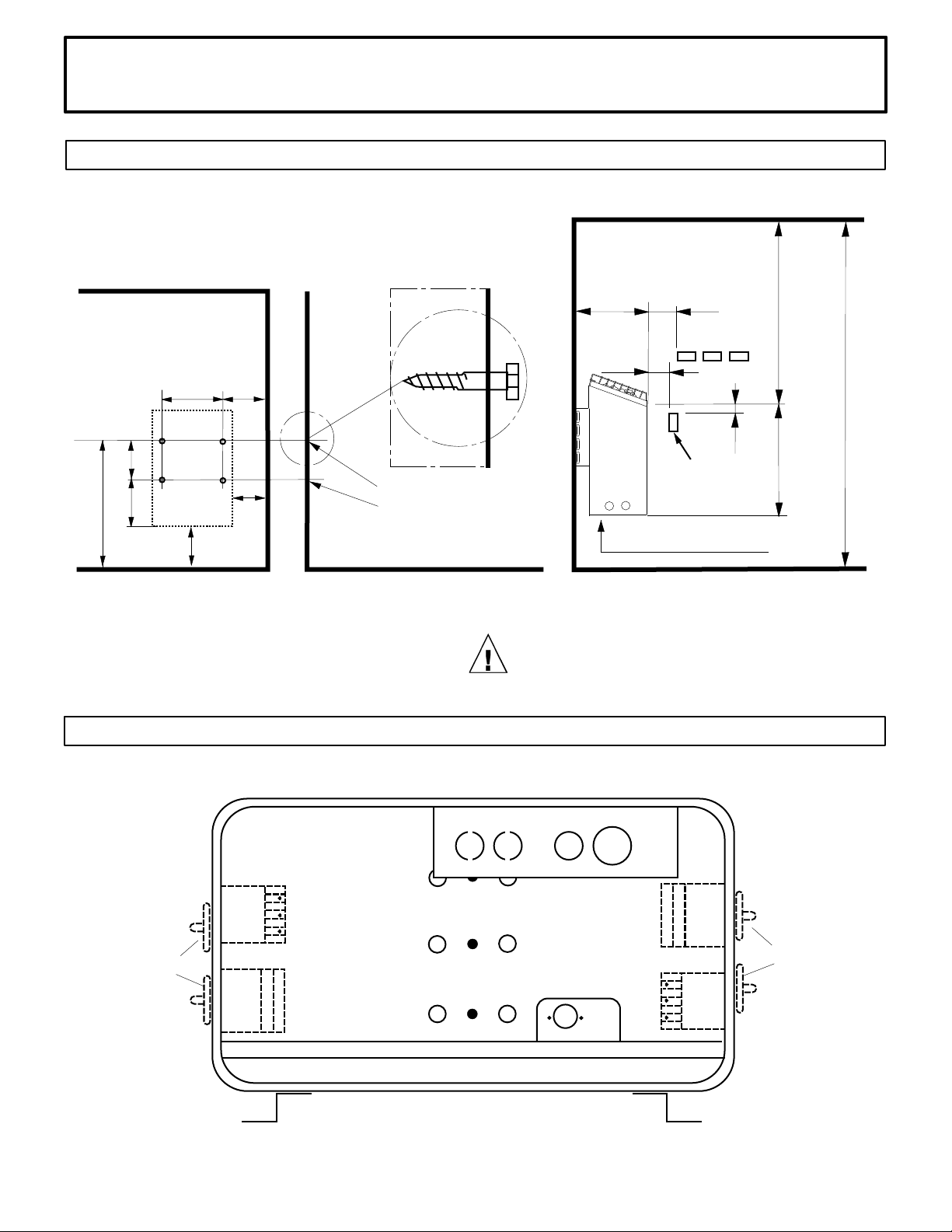
MOVING THE CONTROLS Lay the heater on its back: remove the
control knobs by pulling them straight off (See Item 1 on Diagram 3);
unsnap the plastic hole plugs from the left and right sides of the heater
enclosure. Remove the bottom cover by sliding it towards the back of
the heater about 1 inch and then pulling the middle of the plate towards
the bottom of the heater. The metal plate will flex slightly and come out.
Remove the screws which hold the mounting bracket with the controls,
then carefully move assembly to their new position. Reassemble in the
reverse order using the original hardware. Ensure that no wires are
pulled loose, pinched, kinked, pulled tight or otherwise damaged. Use
the plastic hole plugs to cover the unused control mounting positions.
Reinstall the metal plate on the bottom of the heater.
HANGING THE HEATER Using the template provided, drill four
9/64" holes to fasten the heater to the wall. Install two ¼" x 1 ½" hex
head lag screws (supplied with the heater) into the upper two holes.
Tighten these screws until their heads are about 1/8" from the wall
surface. The screws must be threaded through the wall into a framing
member or backing board to support the heater weight. Hang the heater
on the two upper screws.
Locate the two ¼" x 1" hex head lag screws (supplied with the heater)
then install them into the two lower mounting holes. Tighten to lock the
heater in place.
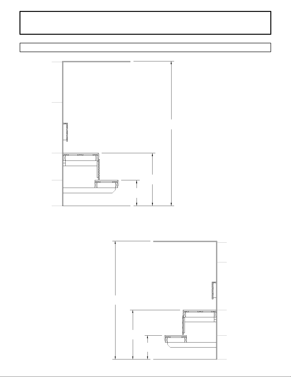
See Diagram 1 & 2 for the heater location details and the necessary
clearances to combustible materials.
The rocks supplied with the heater have been chosen to provide the best
heater performance. Use of any other type of rock may void the heaters
warranty. Never operate the heater without rocks in place!
Rinse the rocks with water before placing in the heater. Carefully place
the rocks loosely so that the air can circulate through the heater. Packing
the rocks too tightly may cause the heater high limit switch to trip. The
rocks must fully cover the heating elements. Attach the guard with the
screws provided.
Fire sprinkler systems used
inside any sauna room should
be properly rated for sauna
room temperatures.
Do not pour chlorinated pool
or spa water on heater.
Excessive water use on heater
may cause damage and void
warranty.
Electric Shock Hazard - High
voltage exists within this
equipment. There are no user
serviceable parts in this
equipment. All installation
and service to this equipment
should be performed by
qualified licensed personnel
in accordance with local and
national codes.
Do not construct sauna room
so as to restrict air flow
through the bottom of the
heater.
Packing the rocks too tightly
may cause the heater high
limit switch to trip.

4211-860-G 04/04/18 7013544 314 SKSM 210 D
INSTALLATION AND OPERATING INSTRUCTIONS Page 4
DIAGRAM 3 DIAGRAM 4
DIAGRAM 5
1.
2.
OFF
15
30
45
60
60 MINUTE TIMER OPERATION
MOVING THE CONTROLS
1. Remove knobs.
2. Remove screws on side of heater.
WIRE
SIZE
Floor Area
Wall
Height
Volume
Cu.Ft.
Ceiling
Height
Volume
Cu.Ft.
Power
Supply to
Heater
1 208 21.6 2 #10AWG+GR
1 240 18.8 2 #10AWG+GR
3 208 12.5 3 #12AWG+GR
3 240 10.8 3 #12AWG+GR
1 208 28.8 2 #8AWG+GR
1 240 25 2 #10AWG+GR
3 208 16.7 3 #12AWG+GR
3 240 14.4 3 #12AWG+GR
1 208 38.5 2 #8AWG+GR
1 240 33.3 2 #8AWG+GR
3 208 22.2 3 #10AWG+GR
3 240 19.2 3 #10AWG+GR
AMPS
4.5 kW
Heater
1712-450-17
4.5 12 sq. ft. 74" 100 96" 210
HEATER
MODEL /
Product
Number KW
MINIMUM ROOM MAXIMUM ROOM
PHASE VAC
310
8.0 kW
Heater
1712-800-17
8.0 31 sq. ft. 74" 250 96" 425
6.0 kW
Heater
1712-600-17
6.0 21 sq. ft. 74" 175 96"

4211-860-G 04/04/18 7013544 314 SKSM 210 D
INSTALLATION AND OPERATING INSTRUCTIONS Page 5
SECTION 4: ELECTRICAL HOOK-UP
SECTION 5: HEATER SCREEN (GUARD RAIL)
SECTION 6: OPERATION
Electrical installation must be made by a licensed electrician in
accordance with the National Electrical Code and local regulations.
Remove the access cover from under the heater. Route the feed wires
through the holes provided in the bottom of the heater and connect the
wires to the terminal block. To determine the correct wire size, refer to
Diagram 5. Use copper supply wire only, suitable for minimum 90
degrees C. The heater must be grounded! See Diagram 6 for proper
connections.
Install a wooden heater guard to prevent the sauna bather from
accidentally touching the sauna heater. Install the heater guard rail with
the height clearances and dimensions shown in Diagram 8.
The heater is provided with a thermostat to adjust the sauna bath
temperature and a timer to control when the bath starts and stops. For
health and fire safety, never attempt to alter or bypass the timer or
thermostat. If the sauna is to be used without an automatic timer
provided, an attendant must be present at all times.
SETTING THE TEMPERATURE The temperature can be adjusted by
turning the thermostat knob. To raise the temperature, turn the knob
clockwise; to lower the temperature, turn the knob counter-clockwise.
SETTING THE TIME If you want the heater to begin heating
immediately, turn the dial full clockwise. The timer will be set for a 60
minute heat cycle.
Do not locate benches over
heater. Minimum clearance of
ceiling above heater 44".
Minimum clearance from
heater to wooden surfaces
(benches, side walls, heater
fence etc.) 2 inches.
Mounting brackets supplied.
Provides proper clearance
from wall behind heater.
Use only copper wire of the
size and type indicated in the
Heater Specification Chart
and the temperature rating
indicated on the heater
junction box.
All heaters and controls must
be grounded per NEC to
prevent electrical shock in
case of unit failure.
Electrical outlets or
receptacle must not be
installed in a sauna room.
A guardrail or fence is
required around the heater to
prevent burns from accidental
contact.
WARNING

4211-860-G 04/04/18 7013544 314 SKSM 210 D
INSTALLATION AND OPERATING INSTRUCTIONS Page 6
DIAGRAM 6
Heater Input Heating Elements
208V or 240V
Model kW 1500 W 2000 W 2670 W
1712-450-17 4.5 3
1712-600-17 6.0 3
1712-800-17 8.0 3
M
Timer
Contactor
Thermostat
High Limit
Control 123
P1 P2 P3
32
22
12
31
21
11
FRONT
BACK
b
a1
a
b1
2 4 6 8
1 3 5 7
A2
A1
1 hour
MIDDLE
GND
GND L1 L2 L3
240V - 208V, 3-ph
123456
208V...240V, 1-ph
GND
123456
GND L1 L2
See Diagram 5 for supply connections copper wire size
354 SKSM 153C

4211-860-G 04/04/18 7013544 314 SKSM 210 D
INSTALLATION AND OPERATING INSTRUCTIONS Page 7
SECTION 7: HIGH LIMIT CONTROL (RESET BUTTON)
SECTION 8: HOW TO TAKE A SAUNA
The sauna heater has a built-in high limit control, which automatically
turns off the heater if the temperature inside in the sauna room rises to
an abnormally high level.
To restart the heater, let the heater cool and turn the timer down to zero
(off), then push the reset button on the bottom of the heater (See Item 3
on Diagram 2). If the high limit continually shuts off the heater, refer
to Section 13.
• When taking a sauna, allow time to relax completely.
• Remove clothing and jewelry...if required, wear a towel loosely.
• After 10 minutes or when perspiration begins, leave sauna and relax in
dressing area...follow with a cool shower.
• Cooling time should equal time spent in sauna. Enter sauna room again
and stay 5 or 10 minutes.
• Repeat the cycle 2 or 3 times; end with a brisk shower...rinse in cool
water.
• Dress when completely dry and perspiration has stopped.
• Some sauna bathers enjoy the soothing effect of steam by splashing
water on the heated sauna rocks. Use only one dipper full (approx. ½
cup) at a time and take care to keep clear of the steam as it rises off the
rocks.
• Do not smoke, exercise or drink alcoholic beverages in the sauna
room.
• Do not pour chlorinated pool or spa water on the heater or corrosion
damage may result.
Shower
Sauna (10 - 15 min.)
Shower or swim
Rest (10 - 15 min.)
Relax with juice or water
You liked it?
Do it once again and
you will feel great.
SECTION 9: WARNING PLACARDS
Three metal placards are included in the Installation Instruction
Envelope packaged with every Sauna Heater. The CAUTION placard
must be attached to the interior wall of the sauna room directly above the
heater where it is visible to the bather. The two WARNING placards
must be attached to the door of the sauna room.

4211-860-G 04/04/18 7013544 314 SKSM 210 D
INSTALLATION AND OPERATING INSTRUCTIONS Page 8
DIAGRAM 7
Locate vent under
the top bench
TYPICAL PRE-CUT WALL CONSTRUCTION
2x4" framing 1/2" wallboard
fiberglass insulation
1/2" wallboard
T&G soft wood
foil vapor barrier
HEATER SCREEN (GUARD RAIL)
DIAGRAM 8
VENTILATION
DIAGRAM 9
c. Loosely cover the tops of
all elements a minimum
of 2" to 3".
High Limit
Sensor
Rocks between
the front element
and the outer wall
will reduce cycling
of the heater.
b. Rocks must be placed between the
elements and the wall of the rock compartment.
Incorrect Placement
of Rocks
a. Loosely place rocks between
the elements so air flow is not
restricted.
Rock Grate
Wall Bracket
1. Put smaller rocks in first around the outer perimeter of the
heating chamber.
2. Completely fill all four sections (front, 2 center sections
between elements, and back).
3. In the outer sections, use smaller rocks placed more tightly (see
note b).
4. Place rocks loosely in the center 2 sections (see note a).
5. Be sure rocks completely cover the elements (see note c).
6. Loosely cover the tops of all elements a minimum of 2” to 3”.
Minimum Dimensions
DIAGRAM 10

4211-860-G 04/04/18 7013544 314 SKSM 210 D
INSTALLATION AND OPERATING INSTRUCTIONS Page 9
WARNING
SECTION 10: ROOM CONSTRUCTION
For safety purpose sauna
door must open out and not
lock.
Never use a wood stain, seal
or preservative on the inside
of your sauna room.
Light fixtures get very hot
during operation. Locate
light fixture where it will not
be a burn hazard.
The "CAUTION" and
"WARNING" placards must be
mounted in accordance with
Section 9.
For safety and reliability, the following rules must be addressed.
• No permanent locking or latch system is to be used on the sauna door.
• Acceptable door fittings are: magnetic catches, friction catches, spring
or gravity loaded closures. The door must always open outwards.
• No shower may be installed in a sauna room.
• No electrical receptacle shall be installed inside the sauna room.
• The enclosed WARNING: Reduce the risk of overheating … warning
plate must be mounted on or alongside the door outside the sauna room
at about eye level.
• The enclosed CAUTION: Reduce the risk of fire … caution plate
must be mounted on the interior wall above the heater.
• The heater should not be operated without its container properly filled
with rocks and the rock guard in place.
• If an intercom speaker is installed, it should be away from the heater
and as close to the floor as possible.
• If a room light is installed, it should be a surface mounted bracket
type. Wall mounted lights should be about 70" above the floor. Ceiling
mounted lights should be of an approved type with a junction box that is
remote to the fixture itself. Use only a fixture that uses A.F. or fixture
type internal wiring. A 60 watt bulb should provide sufficient lighting.
• Fire sprinkler systems installed inside any sauna room should be
properly rated for sauna room temperatures.
• Always mount the heater according to these installation instructions.
SECTION 11: VENTILATION
VENTILATION In a sauna, the air should be changed about 6 times an
hour. This can be achieved by making a vent opening (fresh air inlet) in
the sauna wall directly below the heater. The air outlet must be lower
than the upper benches, as far as possible from the heater and about two
feet higher than the fresh air inlet vent, See Diagram 9.
It is recommended that ventilation openings meet the requirements of UL
Specification 875. The minimum opening should be determined using
one of the following formulas:
For R<31, V³9.3
For R³31, V³0.3R
where R = the floor area of the room in square feet and
V = the minimum vent size in square inches

4211-860-G 04/04/18 7013544 314 SKSM 210 D
INSTALLATION AND OPERATING INSTRUCTIONS Page 10
DIAGRAM 11: ROOM TEMPERATURES
Notes:
Temperatures vary in a sauna room by height
and distance from heater.
Ventilation will help reduce it but will not
eliminate temperature variations.
The hottest part of the room is always at the
ceiling directly above the sauna heater and
should not exceed 194°F (90°C).
Air temperature will be 15°F to 25°F lower
on the opposite side of the room from the
heater close to the ceiling.
The temperatures in the elevated view are
general numbers. Each sauna room is differ-
ent due to construction variations and venti-
lation.
Lower Bench
Upper
Bench
Floor
Ceiling
Lower Bench
Bench Support
Bench Support
Upper Bench
Floor
Ceiling
Head Height
Head Height
190° F
160° F
140° F
100° F
85° F
190° F
140° F
125° F
95° F
85° F
Non-Typical Ceiling Height
Typical Ceiling Height
17"
17"
35"
84"
35"
96"

4211-860-G 04/04/18 7013544 314 SKSM 210 D
INSTALLATION AND OPERATING INSTRUCTIONS Page 11
No Heat - Check timer, refer to Section 6 and Diagram 4 about timer operation.
No Heat - Press (reset) the high limit switch on the bottom of heater, refer to Section 7 and Diagram 2 for
location of reset switch.
Low Heat or Slow Heat Time or High Limit Tripping - Check rock placement, they will break down over
time and reduce the air flow in the heater. Refer to Diagram 10 for proper rock installation. Discard all rocks
under the size of 2" pieces. Call the number below to order more rocks if needed.
For troubleshooting or service questions call 1-888-780-4427 and ask to speak with service. Prior to calling,
please have the Model and Type number available. You may also email us at
SECTION 12: MAINTENANCE
The sauna, like a bathroom, should be kept clean and odor free.
Towels or mats should always be used on benches and floor as perspiration otherwise penetrates the soft
wood.
Air out the sauna often by keeping the door and vents open when the sauna is not in use. Saunas that are in
daily use should be washed down at least once a week to keep them clean and the air fresh. Duckboard should
be removed from the sauna, the sauna floor mopped and dried in a conventional manner, and the duckboard
thoroughly scrubbed and dried before returning to the sauna room. The sauna heater should be wiped down
occasionally with a damp cloth to remove lint and dust. The rocks should be removed once a year for
cleaning and small or crumbled rocks replaced.
To clean and remove perspiration stains, use soap or detergent in warm water, best applied with a scrub brush.
Badly soiled surfaces may require sanding. Sand paper wrapped around a wooden block works well.
Benches and supporting structure must be inspected annually for potential deterioration due to age, dry rot or
abuse. Any boards with signs of deteriorations should be replaced immediately to avoid possible injury.
SECTION 13: TROUBLESHOOTING

4211-860-G 04/04/18 7013544 314 SKSM 210 D
INSTALLATION AND OPERATING INSTRUCTIONS Page 12
SECTION 14: REPLACEMENT PARTS
Number Part # Description Qty
1 8012-511 Shroud: Red No Brand logo 1
2 8019-515 Rock Guard (Black) 1
3 8012-448 Top: (Black) 1
4 8250-085 Wall Bracket 1
8201-114 High limit Bracket 1
5 2140-574 Knob (Timer) 1
6 2140-573 Knob (Thermostat) 1
7 3140-28 Timer 1
8 3155-622 Thermostat 1
9 1000-03 Screw 2
10 3131-517 Contactor 1
11 2100-550 Terminal Block 1
12 3119-510 High Limit 1
13 8012-452 Electric access panel 1
14 8019-209 Rock Grate 1
15 2138-08 Plugs (For knob holes) 2
16 3001-702 Element 208V/1500W (45) 28.8 ohms 3
16 3001-704 Element 208V/2000W (60) 21.6 ohms 3
16 3001-706 Element 208V/2670W (80) 16.2 ohms 3
16 3001-701 Element 240V/1500W (45) 38.4 ohms 3
16 3001-703 Element 240V/2000W (60) 28.8 ohms 3
16 3001-705 Element 240V/2670W (80) 21.6 ohms 3
1021-110 Element screw
This manual suits for next models
7
Table of contents
Other TyloHelo Heater manuals
Popular Heater manuals by other brands

Klarstein
Klarstein Hot Spot Crystal Flow manual

Taurus
Taurus ALPATEC TROPICANO S2001 manual

Dyna-Glo
Dyna-Glo WORKHORSE FA43 Series User's manual and operating instructions

Tesla
Tesla PC312WD user manual

HEATSTRIP
HEATSTRIP THH1500AEU Operation, installation, and maintenance manual

EQUATION
EQUATION HD15BDC Assembly, Use, Maintenance Manual