Tysso PRP-076N User manual

User’s Manual
PRP-076N
PRP-076C
PRP-076D
Impact Dot-Matrix Printer
Specifications subject to change without notice

1
Table of Contents
1. General Information ………………………………………………………………..2
1.1) Models
1.2) Features
2. Quick Start…………………………………………………………………………..3
2.1) Unpacking & Parts Identification
2.2) Loading the Paper Roll and Ink Ribbon
3. Printer Interface and Connection……………………………………………………5
3.1) Connecting the Interface Cable
3.2) Connecting to a Cash Drawer
3.3) Connecting the AC Adapter
4. Configuration………………………………………………………………………..7
4.1) Printer Status
4.2) DIP Switch Settings
4.3) Printer Self Test
4.4) Hexadecimal Dumping
4.5) Driver Installation
5. Safety and Maintenance……………………………………………………………11
5.1) Safety Information
5.2) Periodical Cleaning
5.3) Preventing Paper Jams
5.4) Fixing Paper Jam
6. Appendix………………………………...………………………………………....13
- Product Specifications
- General Printer Commands
- International Character Fonts

2
1. General Information
1.1) Models
Note: International font can be combined with others languages, for example
PRP-076C-BI-M-S, with cutter, Big5+International, beige, serial interface.
1.2) Features
Main Features:
-3.5 characters line/sec / 4.5 characters line/sec (32 bit ARM CPU)
-76 mm ± 5 mm Max. label width
-Low-noise dot matrix printing
-High reliability due to a stable mechanism
-Command protocol is based on the ESC/POS standard
-Support black mark anchor testing print
-Various Layouts are possible by using page mode
-Repeated operation and copy printing are possible
-Easy paper-roll installation
-Easy paper jam clearance
-Easy maintenance for tasks such as head cleaning
-Built-in interface provides control capability for cash drawer
Available fields:
-Print POS system receipts
-Print EFT POS system receipts
-Print gym, post, hospital, civil aviation system receipts
-Print inquiry, service system receipts
-Print instrument test receipts
-Print tax, tab receipts
2. Quick Start

3
2.1) Unpacking & Parts Identification
Unpacking:
Parts Identification:
Power switch

4
2.2) Loading the Paper Roll and Ink Ribbon
a. Make sure that the paper roll matches the printer’s specification. Do not use paper rolls that
have the paper glued to the core because the printer cannot detect the paper end correctly.
Important: The printing quality and lifespan of the printer head cannot be guaranteed if
any paper other than that recommended is used. Thus, the warranty will be void
automatically if any fault occurs due to the use of wrong paper rolls.
b. Open the top cover
Important: Do not open the printer cover when printing is in progress.
c. Install the paper roll as the picture showing direction
d. Pull the paper out of some length to outside, then close the cover.
e. Open the printer’s cover, turn the knob five or six times in the direction of the arrow, insert
the ink ribbon, and push the ribbon cassette down until it clicks.
Open Cover

5
3. Printer Interface and Connection
3.1) Connecting the Interface Cable
Printer Interface:
a) Before connecting/disconnecting the interface cable, make sure that power to the printer and
all the devices connected to the printer is turned off.
b) Connect the interface cable to the connector on the rear panel of the printer.
c) In the case of a serial interface, tighten the connector screws. In the case of a parallel interface, fasten
the connector clasps.

6
3.2) Connecting to a Cash Drawer
Important:
zMake sure that the printer is turned off and unplugged from the AC outlet and that the
computer is turned off before making connections.
zDo not connect a telephone line into the peripheral drive connector. Failure to observe this
may result in damage to the printer.
3.3) Connecting the AC Adapter
a. Connect the AC power cord to the inlet ofAC adapter, and then connect the power cord plug
to a suitable electrical outlet.
b. Connect the adapter cable to power connector of printer; make sure the printer power switch
is OFF before making any connections.

7
CAUTION:
DO NOT USEANYAC POWER ADAPTERS OTHER THAN SPECIFIED.
c. Turn on the power switch; the POWER lamp on the control panel will light up.

8
4. Configuration
Printer Control Panel & Status Indication
4.1) Printer Status
zPower (POWER) LED: Green
On: Power is on.
Off: Power is off.
zError (ERROR) LED: Red
On: Offline (except during paper feeding using the FEED button and test printing,
and the error state.)
Off: Normal condition.
zPaper roll end (PAPER) LED: Red
Flash: The paper roll end is detected.
Off: Paper is loaded (Normal condition).
zFEED (Button)
Press the FEED button to feed roll paper.
Press the FEED button for 1 second and the roll paper will be fed continuously.
9
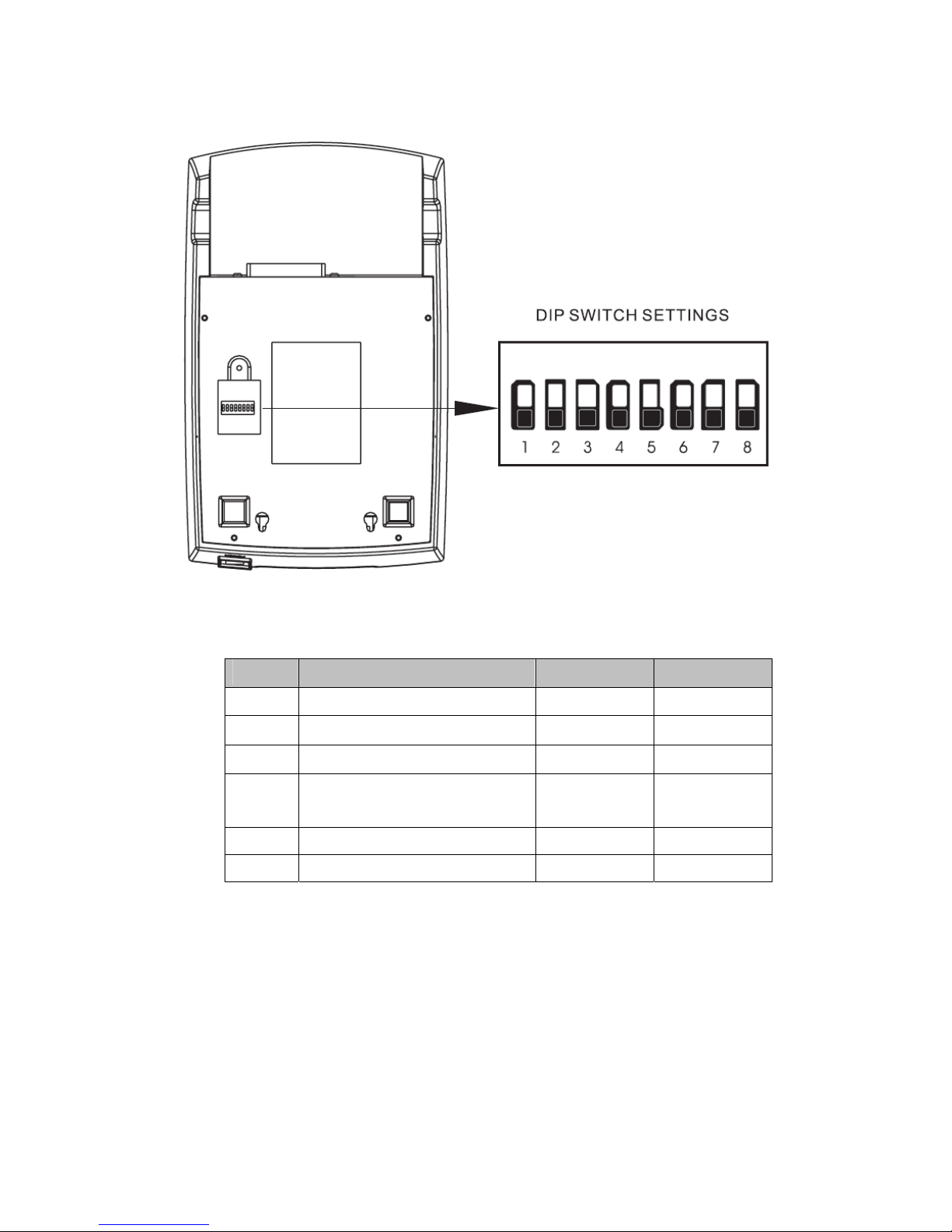
4.2) DIP Switch Settings
The DIP switch panel is locating at bottom of the printer as shown:
DIP Switch Functions:
SW 7 SW 8 Baudrate
On On 38400
Off On 4800
On Off 9600
Off Off 19200
Note:
Before configure the DIP switch settings, please first turn the printer power off and remove
the paper roll.
Switch Function ON OFF
1 Black mark mode No Yes
2 Select Cutter No Yes
3 Cut mode Partial Full
4 Select characters per line (CPL) 7
x 9 / 9 x 9
40CPL/33CPL 42CPL/35CPL
5 Unidirectional No Yes
6 Two-byte character Yes No
This manual suits for next models
2
Table of contents
Other Tysso Printer manuals

Tysso
Tysso PRP-300 User manual

Tysso
Tysso PRP-350 User manual

Tysso
Tysso PRP-058-S User manual

Tysso
Tysso PRP-058K User manual

Tysso
Tysso PRP-085 Series User manual

Tysso
Tysso PRP-250 User manual

Tysso
Tysso PRP-100 User manual

Tysso
Tysso PRP-350 User manual

Tysso
Tysso PRP-300 User manual

Tysso
Tysso PRP-080 Series User manual


