U-Line H-3701 User manual

PAGE 1 OF 33 1023 IH-3701
110 "SEMI-AUTOMATIC
STRETCH WRAP
MACHINE
H-3701 1-800-295-5510
uline.ca
SYSTEM SPECIFICATIONS
MACHINE DIMENSIONS
Length 98"
Width 60"
Height 131"
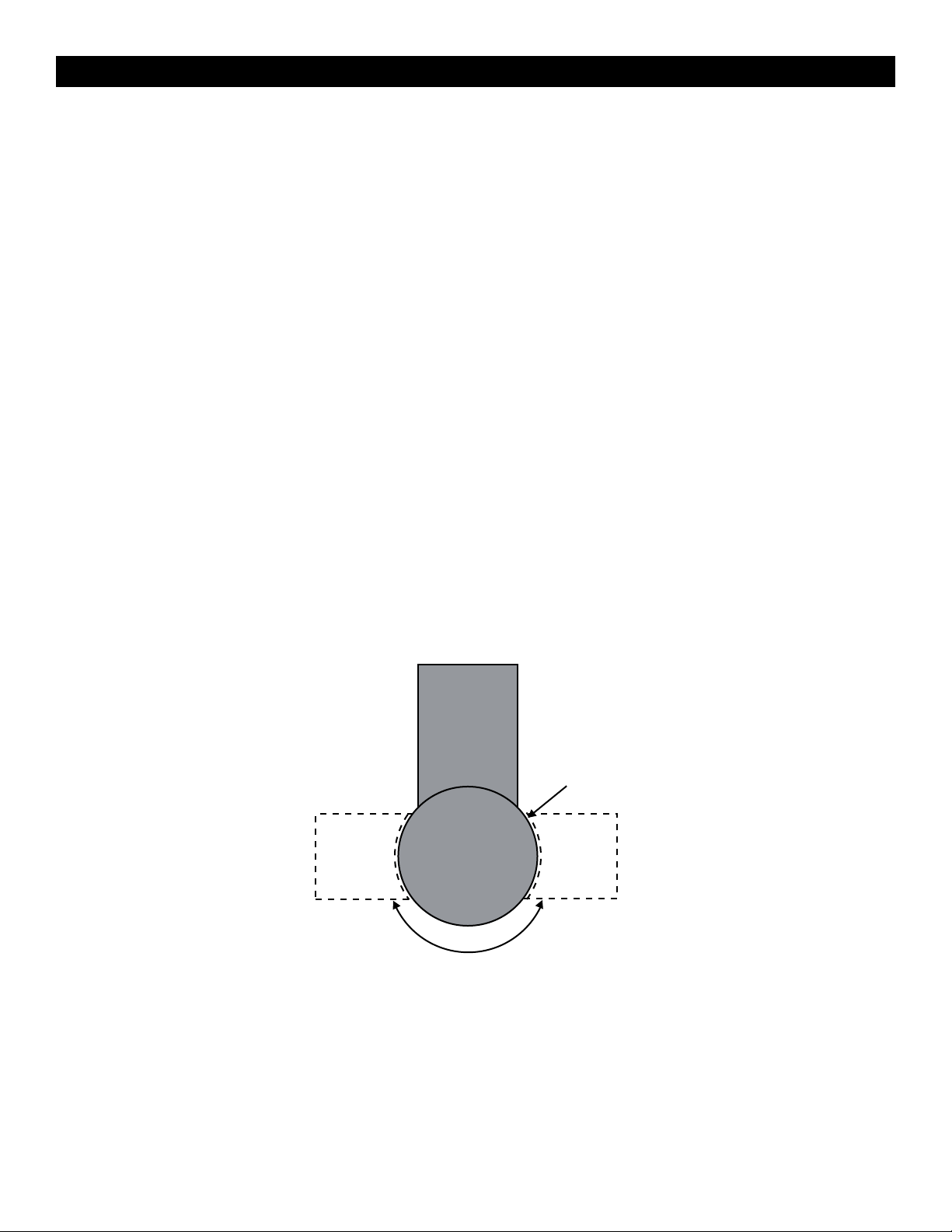
Turntable Diameter 60"
Turntable Height from Floor 3/"
Wrapping Height 110 "
Operation Space 98 x 60 x 129"
Maximum Load Size 52 x 52 x 110"
Approximate Shipping Weight 1,250 lbs.
ELECTRICAL SPECIFICATIONS
• 115 VAC, 60 Hz, Single-phase, 15 AMP
TURNTABLE SYSTEM
• 20 loads per hour (spiral)
• 12 RPM turntable maximum speed
• 4,000 lbs. turntable maximum load capacity
FILM CARRIAGE / ELEVATOR SYSTEM
• Adjustable raise and lower speeds
• Automatic height detection photoelectric sensor
FILM DELIVERY SYSTEM
• Infinite / Manual Stretch Adjustment
• 10" Diameter Roll Capacity
• 20" Roll Width Capacity
CAUTION! Motor control equipment and
electronic controllers are connected to
hazardous line voltages. When servicing
drive and controllers, there may be exposed
components with housings or protrusions at or
above line potential. Extreme care should be
taken to protect against shock.
WARNING! Loose clothing must NOT be worn
while the machine is in operation. Stay clear
of moving parts while the machine is running.
• The user is responsible for conforming to all
applicable code requirements with respect to
grounding requirements. Do NOT use extension
cords to operate the equipment.
• Do not plug into GFCI outlets.
• Disconnect AC input power before checking
components, performing maintenance, cleaning
up, and when the machine is not in use. Do NOT
connect or disconnect wires and connectors while
power is applied to circuit.
• Wiring work should be performed only by qualified
personnel. There is a danger of electric shock or fire.
Para Español, vea páginas 12-22.
Pour le français, consulter les pages 23-33.

PAGE 2 OF 33 1023 IH-3701
SYSTEM DESCRIPTION
Motor Box
Film Carriage
Stretch Handle
Tower Control Box
Tension Adjustment Knob
Foot Safety Bar
Seat
Turntable

PAGE 3 OF 33 1023 IH-3701
SYSTEM SET-UP
MACHINE PLACEMENT
Place the Automatic Stretch Wrap Machine close to
an area where you will be wrapping your pallet loads.
Make sure that there is sufficient room to load/unload
the machine and that you do not stretch the wiring
cable. Remember, you will need to provide electrical
service to a 120 VAC, 15-AMP outlet.
FLOOR WEIGHT BEARING TOLERANCE
The floor must be able to bear the weight of the
machine, the weight of the maximum load, plus a
safety factor. The floor must also be able to tolerate
the stress of the machine's operation. If fork trucks
will operate on the same weight bearing area, add
the weight of the trucks to the weight bearing stress
tolerance requirements.
MACHINE SET-UP
1. Place skidded machine close to the designated
wrap area. Remove all shipping fasteners holding
the machine to the pallet. The machine may be
crated with the tower tilted down with the motor
cover front carriage roller removed for shipping
purpose.
2. Place forks of the forklift through the tubes provided
at the rear base of the module, remove the
machine from these skids, and place it at the
designated wrap area.
3. If the OPTIONAL ramp (H-1071) is purchased:
Select a ramp position as illustrated below. The
ramp can be positioned anywhere in a 180°
rotation around the front of the turntable. There
should be a 1/4" gap between the turntable and
the ramp. The ramp should be fully supported by
the floor. (See Figure 1)
1/4"
Gap
180°
Figure 1

PAGE 4 OF 33 1023 IH-3701
1. The Automatic Stretch Wrap Machine will arrive with
similar crating to what is shown to the right. Please
remove the protective packaging and prepare the unit
to stand up. (See Figure 2)
2. Once the machine has been successfully uncrated, the
next step is to begin erecting the tower. Start by leaning
the tower until fully upright. (See Figure 3)
CAUTION: Heavy Materials! Two or more
people are required for assembly.
3. Align the 5 bolts in the threaded inserts and tighten
completely. Next, the carriage will need to be
mounted to the tower. (See Figure 4)
CAUTION: Always have one or more people
supporting the tower while tightening bolts.
4. To mount the carriage, start by removing the bottom
4 bolts from the carriage mount bracket. (See Figure 5)
ASSEMBLY INSTRUCTIONS
Figure 2
Figure 3
Figure 4
Figure 5

PAGE 5 OF 33 1023 IH-3701
TURNTABLE
ASSEMBLY INSTRUCTIONS CONTINUED
5. Loosen the top 2 bolts to hang the carriage in place.
(See Figure 6)
6. Align the top two bolts with slotted bolt holes at the top of
the carriage and hang in place. (See Figure 7)
7. The next step is to remount the photo sensor from its
protected shipping position. (See Figure 8)
8. Tighten up all 6 bolts on the back of the carriage.
(See Figure 9)
TURNTABLE
TURNTABLE
Figure 6
Figure 7
Figure 8
Figure 9

PAGE 6 OF 33 1023 IH-3701
CONTROL BOX
TURNTABLE SPEED CARRIAGE SPEED
START BANDING
BOTTOM
WRAPS
TOP
WRAPS
TURNTABLE
JOG
WRAP
MODES
SYSTEM
RESET CARRIAGE
JOG
INFO

PAGE 7 OF 33 1023 IH-3701
CONTROL BOX CONTINUED
LED DISPLAY
EO Emergency Stop Condition
- - System is normal
A Mode A Selected
B Mode B Selected
CO Continue operation by pushing START button
S System is in Manual
BUTTONS
WRAPPING MODE A - WRAP UP AND DOWN
The LED on the button's upper left is on. In Mode A, the bottom wrap is applied first, and then
the top wrap follows. The film carriage comes down to its home position after wrapping cycle is
finished.
WRAPPING MODE B - WRAP UP ONLY
The LED on the upper left is on. In Mode B, after a bottom to top wrapping is completed, the
carriage stays on the top. The START button flashes at this point. To resume the operation, push
START. When the carriage reaches the bottom, the START button turns off. Push START button again
to begin a new cycle.
The TURNTABLE JOG button allows you to manually operate the turntable. When this button is
pushed, the light on the button's upper left is on. Push START button to run the table. Pushing
the button again will stop the turntable and the light will turn off. This button may be used in
conjunction with the CARRIAGE JOG button.
The CARRIAGE JOG button allows you to manually operate the carriage. When this button is
pushed, one of the lights on the button's upper right or left is on. The upper left light indicates
that the carriage will go up when the START button is pushed. Conversely, the upper right light
indicates the carriage will go down when the START button is pushed. To pause operation, simply
push this button again. Both indicator lights will go off. This button may be used in conjunction
with the TURNTABLE JOG button.
Push this RESET button, followed by the START button, to reset the system. The turntable will return to
its home position and the carriage will lower.
Push the TOP WRAPS button to select the number of top wraps desired (0 - 9).

PAGE 8 OF 33 1023 IH-3701
CONTROL BOX CONTINUED
Push the BOTTOM WRAPS button to select the number of bottom wraps desired (0 - 9).
Turn the CARRIAGE SPEED adjustment knob clockwise to increase, and counterclockwise to
decrease the carriage speed. This allows you to adjust the overlap of your film.
Turn the TURNTABLE SPEED adjustment knob clockwise to increase, and counterclockwise to
decrease the turntable speed.
The BANDING button is used for applying multi-layer reinforcing wraps in automatic or manual
mode. Push and hold this button: the carriage will stop raising / lowering. When released, the
carriage will resume its movement.
The EMERGENCY STOP button stops the turntable in the event of emergency. This will NOT stop the
turntable instantly. The turntable will coast to a stop, depending on the load's weight, after this
button is pushed.
This switches the main power ON or OFF.
WARNING! The FOOT SAFETY BAR, located underneath the film carriage works only when
the machine is ON. When the bar is activated, the main power will shut OFF. Releasing
the bar will reactivate the main power. Push START button to resume the operation.

PAGE 9 OF 33 1023 IH-3701
MACHINE OPERATION
FILM LOADING
CAUTION! Be sure EMERGENCY STOP is pushed
in before threading the film and pulled out
when the film is threaded.
1. Place the film on the film mandrel.
2. Set the Stretch Handle to the OFF position to release
film tension.
3. Follow the Film Feed Diagram and thread the 6 foot
film tail ALL THE WAY through the rollers.
4. Set the Stretch Handle to the OFF position to release
film tension.
5. Rotate the Stretch Tension Adjustment
Knob clockwise to increase film tension or
counterclockwise to decrease film tension.
6. Attach the film securely to the pallet. Tying the end
of the film in a knot often helps secure the film to
the pallet.
NORMAL SYSTEM START-UP
1. Place the film on the film mandrel.
2. Set the Stretch Handle to the OFF position to release
film tension.
3. Thread the film as instructed and attach it to the
product.
4. Set the desired numbers for top and bottom wrap
counts.
5. Select wrapping mode A or B.
6. Press the START button to initiate cycle.
STOP CONDITION
1. In the event of an emergency, press the STOP
button. This cancels the current wrapping cycle
and immediately stops the system. The turntable will
coast to a stop.
2. Correct the problem
3. Pull the STOP button out and perform normal system
start-up procedure.
NOTE: After pressing the STOP button, wait for
at least 60 seconds before pulling the button
back out. This will allow the microcontroller
card to completely turn off.
APPLYING REINFORCEMENT WRAPS
1. Press the START button as normal to initiate cycle.
2. As the carriage travels up, press and hold the
BANDING button. The carriage will stop and
reinforcing wraps will be applied.
3. Letting go of the BANDING button will resume the
cycle.
LESS
STRETCH
50
0100
MORE
OFF
ON
Stretch Tension
Adjustment Knob
Film Feed
Diagram
Stretch Handle
(Off Position)
Stretch Tension
Indicator
Figure 10

PAGE 10 OF 33 1023 IH-3701
SELF-TEST PROCEDURE
An operator may check the status of the machine
by running a self-test. If the procedure is carried out
properly, the INFO screen will display the location of the
problem(s).
To run the self-test, follow the procedure below:
1. Turn the turntable and carriage speed adjustment
knobs to maximum (clockwise) position.
2. Put a load on the turntable (about 3 feet tall).
3. While holding down the TURNTABLE JOG and
CARRIAGE JOG buttons, turn the main disconnect
switch ON.
4. Release the buttons after the screen shows EE.
5. Push the START button. The machine will run the test,
which takes approximately 2 minutes.
6. The screen will display the alarm code. Refer to the
table below for code information.
A1
F1
E1
G1
B1
C1
D1
B2
A2
C2
DISPLAY POSSIBLE PROBLEM LOCATION(S)
A1 Film carriage Safety Bar
EMERGENCY STOP button
Electrical enclosure safety switch
B1 Film carriage max upper limit switch
C1 Film carriage max down limit switch
D1 Turntable count/home proximity switch
E1 BANDING push button
F1 START push button
G1 Package height photo sensor
A2 START light
B2 Turntable motor
C2 Carriage motor

PAGE 11 OF 33 1023 IH-3701
TROUBLESHOOTING
WARNING! Make sure that only qualified
personnel perform inspection, troubleshooting
and part replacement.
CAUTION! Disconnect all power, including
external control power that may be present,
before servicing the frequency drive
controllers. WAIT for three (3) minutes for the
DC bus capacitors to discharge. The
frequency drive controller's display and/or LEDs
are not accurate indicators of the absence of
DC bus voltage.
OPERATING ISSUE CAUSES RECOMMENDATIONS
Machine not powering on. Main power is turned off. Check that power is going to the machine. Verify that switch
is turned on.
Machine not plugged into 120VAC outlet. Verify the voltage going to the machine matches the power
supply labels on the power module.
Power supply faulty.
Internal battery not charged.
Film carriage foot engaged. Remove obstruction from Film Carriage foot.
Film carriage malfunctioning. FILM CARRIAGE SPEED dial not set high
enough.
Adjust potentiometer towards 100% to set speed.
Resistance of potentiometer not equal to
5K_ across.
Tighten wiring, replace dial if necessary.
The carriage limit switch lever arm is
obstructed.
Remove obstruction and/or clean limit switch head.
Microcontroller card inside electrical
enclosure not turned on.
Check and switch on the main circuit breaker.
Turntable is malfuntioning. Turntable speed potentiometer dial not
set high enough.
Adjust potentiometer towards 100% to set speed.
Resistance of potentiometer not equal to
5K_ across.
Tighten wiring, replace dial if necessary.
Microcontroller card inside electrical
enclosure not turned on.
Check and switch on main circuit breaker.
The turntable motor is not running. Tighten or replace motor wiring as necessary.
Check turntable for mechanical restrictions.
Replace microcontroller or turntable output relav.
1
-800-295-551
0
uline.ca

PAGE 12 OF 33 1023 IH-3701
H-3701 1-800-295-5510
uline.ca
DESPACHADORA
D E 110 "AUTOMÁTICA
DE PELÍCULA ELÁSTICA
DIMENSIONES DE LA MÁQUINA
Largo 249 cm (98")
Ancho 152 cm (60")
Altura 333 cm (131")
Diámetro de Plataforma Giratoria 152 cm (60")
Altura de Plataforma Giratoria desde el Piso 8.3 cm (3 /")
Altura para Envolver 279 cm (110")
Espacio de Funcionamiento 251 x 152 x 328 cm
(99 x 60 x 129")
Tamaño Máximo de Carga 132 x 132 x 279 cm
(52 x 52 x 110")
Peso Aproximado del Envío 567 kg (1,250 lbs.)
ESPECIFICACIONES ELÉCTRICAS
• 115 VAC, 60 Hz, Monofásica, 15 AMP
SISTEMA DE PLATAFORMA GIRATORIA
• 20 cargas por hora (espiral)
• 12 RPM de velocidad máxima de plataforma
giratoria
• Capacidad máxima de 4,000 lbs. de carga de la
plataforma giratoria
SISTEMA DEL PORTADOR DE PELÍCULA/ELEVADOR
• Velocidades ajustables para elevación y descenso
• Sensor fotoeléctrico automático para detección de
altura
SISTEMA PARA DESPACHAR LA PELÍCULA
• Ajuste de Película Infinito / Manual
• Capacidad del Rollo de 25 cm (10") de Diámetro
• Capacidad del Rollo de 50 cm (20") de Ancho
¡PRECAUCIÓN! El equipo de control del
motor y los reguladores están conectados
a líneas de voltaje peligrosas. Cuando
dé mantenimiento a la unidad y a los
reguladores, los componentes pueden estar
expuestos con cubiertas o salientes en o por
encima de la línea de voltaje. Deberá tomar
precauciones extremas para protegerse de
choques eléctricos.
¡ADVERTENCIA! NO debe usar ropa holgada
mientras la máquina esté funcionando.
Manténgase alejado de las partes móviles
mientras la máquina esté operando.
• El usuario es responsable del cumplimiento de
todas las regulaciones relacionadas con la
conexión a tierra. NO use extensiones eléctricas
para operar el equipo.
• No conecte a salidas GFCI.
• Desconecte la alimentación de la corriente
directa antes de revisar los componentes, dar
mantenimiento, limpiar, y cuando la máquina no
esté en uso. NO conecte o desconecte cables
y conectores mientras se suministra energía al
circuito.
• El cableado debe ser realizado sólo por personal
calificado. Existe el peligro de choque eléctrico o
incendio.
ESPECIFICACIONES DEL SISTEMA

PAGE 13 OF 33 1023 IH-3701
DESCRIPCIÓN DEL SISTEMA
Caja del Motor
Portador
de Película
Asa de Película
Torre Caja de Control
Perilla para Ajuste de Tensión
Pedal de Seguridad
Soporte
Plataforma
Giratoria

PAGE 14 OF 33 1023 IH-3701
CONFIGURACIÓN DEL SISTEMA
COLOCACIÓN DE LA MÁQUINA
Coloque la Máquina Automática para Película Elástica
cerca del área en donde envolverá sus tarimas de
carga. Asegúrese de que haya suficiente espacio
para cargar/descargar la máquina y que no se estire
el cable de conexión. Recuerde, necesita tener una
salida para un tomacorriente de 120 VAC, 15-AMP.
RESISTENCIA DEL PISO PARA SOSTENER EL PESO
El piso deberá tener la capacidad de sostener el peso
de la máquina, la carga de mayor peso, además
del factor de seguridad. El piso debe también resistir
la presión del funcionamiento de la máquina. Si se
manejarán montacargas en la misma área de soporte
de peso, agregue el peso de los montacargas a los
requerimientos para la resistencia del peso.
INSTALACIÓN DE LA MÁQUINA
1. Coloque la máquina entarimada cerca del área
designada para envoltura. Retire todos los cinchos
que fijan la máquina a la tarima. La máquina
podría haberse empacado con la torre hacia
abajo y sin la cubierta frontal del rodillo portador
para propósitos de envío.
2. Inserte las horquillas del montacargas a través de
los tubos ubicados en la base posterior del módulo,
retire la máquina de las tarimas y colóquela en el
área designada para envolver.
3. Si compra la rampa OPCIONAL (H-1071): Seleccione
una posición para la rampa como se ilustra abajo.
La rampa puede ser posicionada en cualquier
lugar en una rotación de 180° alrededor del
frente de la plataforma giratoria. Debe haber una
separación de 6.3 mm (1/4") entre la plataforma
giratoria y la rampa. La rampa deberá estar
completamente apoyada en el piso.
(Vea Diagrama 1)
Separación de 6.3 mm (1/4")
180˚
Diagrama 1

PAGE 15 OF 33 1023 IH-3701
1. La Máquina Automática para Película Elástica llegará en
una caja como la que se muestra a la derecha. Retire el
empaque de protección y prepare la unidad para pararla.
(Vea Diagrama 2)
2. Una vez que la máquina ha sido desempacada, el
próximo paso es comenzar a levantar la torre. Empiece
apoyando la torre hasta que esté totalmente de pie.
(Vea Diagrama 3)
PRECAUCIÓN: ¡Materiales Pesados! Se
requieren dos o más personas para
ensamblarla.
3. Alinee los 5 pernos en los insertos roscados y apriételos
completamente. En seguida, el portador necesitará ser
instalado en la torre. (Vea Diagrama 4)
PRECAUCIÓN: Siempre tenga una o dos personas más
para sostener la torre mientras aprieta los pernos.
4. Para instalar el portador, empiece por retirar los 4 pernos
inferiores del soporte de instalación del portador.
(Vea Diagrama 5)
INSTRUCCIONES DE ENSAMBLE
Diagrama 2
Diagrama 3
Diagrama 4
Diagrama 5

PAGE 16 OF 33 1023 IH-3701
TURNTABLE
CONTINUACIÓN DE INSTRUCCIONES DE ENSAMBLE
5. Afloje los 2 pernos superiores para colgar el portador en
su lugar. (Vea Diagrama 6)
6. Alinee los dos pernos superiores con los dos orificios
ranurados para pernos en la parte superior del portador
y cuélguelo en su lugar. (Vea Diagrama 7)
7. El siguiente paso es reinstalar el fotosensor de su
posición protegida para envío. (Vea Diagrama 8)
8. Apriete los 6 pernos en la parte posterior del portador.
(Vea Diagrama 9)
TURNTABLE
TURNTABLE
Diagrama 6
Diagrama 7
Diagrama 8
Diagrama 9

PAGE 17 OF 33 1023 IH-3701
CAJA DE CONTROL
VELOCIDAD
DE PLATAFORMA
GIRATORIA
VELOCIDAD
DEL PORTADOR
INICIO ATAR CON BANDA
ENVOLTURAS INFERIORES
ENVOLTURA
INFERIOR
ENVOLTURA
SUPERIOR
IMPULSO DE
PLATAFORMA
GIRATORIA
MODOS DE
ENVOLTURA
REINICIO AL
SISTEMA IMPULSO DEL
PORTADOR
INFORMACIÓN

PAGE 18 OF 33 1023 IH-3701
CONTINUACIÓN DE CAJA DE CONTROL
PANTALLA LED
EO Posición de Apagado de Emergencia
- - Sistema normal
A Modo A Seleccionado
B Modo B Seleccionado
CO Continúe el funcionamiento presionando el botón START
S El Sistema está en Manual
BOTONES
ENVOLTURA EN MODO A – ENVOLTURA POR ARRIBA Y ABAJO
El LED de la parte izquierda superior del botón está encendido. En Modo A, la envoltura se
aplica primero en la parte inferior, y después sigue la envoltura superior. El portador de la
película baja a su posición de inicio después de terminar el ciclo de envoltura.
ENVOLTURA EN MODO B – ENVOLTURA POR ARRIBA SOLAMENTE
El LED en la parte izquierda superior está encendido. En Modo B, después de que la envoltura
desde abajo hasta arriba está completa, el portador permanece en la parte superior. El botón
START parpadea en este punto. Para reiniciar el funcionamiento, presione START. Cuando el
portador llega a la parte inferior, el botón START se apaga. Presione el botón START de nuevo y
empiece el nuevo ciclo.
El botón TURNTABLE JOG le permite operar manualmente la plataforma giratoria. Cuando este
botón es presionado, la luz en la parte izquierda superior del botón se enciende. Presione el
botón START para poner a funcionar la plataforma. Al presionar de nuevo el botón detendrá la
plataforma giratoria y la luz se apagará. Este botón puede utilizarse en conjunto con el botón de
CARRIAGE JOG.
El botón CARRIAGE JOG permite operar manualmente el portador. Cuando este botón es
presionado, una de las luces en la parte superior derecha del botón se enciende. La luz superior
izquierda indica que el portador irá hacia arriba cuando el botón START sea presionado. Por el
contrario, la luz superior derecha indica que el portador irá hacia abajo cuando el botón START
sea presionado. Para pausar la función simplemente presione este botón de nuevo. Ambas luces
indicadoras se apagarán. Este botón puede utilizarse en conjunto con el botón TURNTABLE JOG.
Presione este botón RESET, seguido por el botón START, para reiniciar el sistema. La plataforma
giratoria regresará a su posición de inicio y el portador bajará.
Presione el botón TOP WRAPS para seleccionar el número de envolturas deseadas en la parte
superior (0-9).

PAGE 19 OF 33 1023 IH-3701
CONTINUACIÓN DE CAJA DE CONTROL
Presione el botón BOTTOM WRAPS para seleccionar el número de envolturas inferiores deseadas (0-9).
Gire la perilla de ajuste CARRIAGE SPEED en el sentido de las manecillas del reloj para aumentar
la velocidad del portador, y en sentido contrario para disminuirla. Esto le permite ajustar la
superposición de su película.
Gire la perilla de ajuste TURNTABLE SPEED en el sentido de las manecillas del reloj para aumentar
la velocidad de la plataforma giratoria, y en sentido contrario para disminuirla.
El botón BANDING es utilizado para aplicar multicapas para reforzar la envoltura en modo
automático o manual. Presione y sostenga este botón: el portador dejará de subir o bajar.
Cuando lo libere, el portador reanudará su movimiento.
El botón EMERGENCY STOP detiene la plataforma giratoria en caso de emergencia. Esto NO
detendrá la plataforma giratoria inmediatamente. La plataforma giratoria se detendrá por
inercia, dependiendo del peso de la carga, después de que el botón sea presionado.
Este cambia el interruptor principal a Encendido o Apagado.
¡ADVERTENCIA! El PEDAL DE SEGURIDAD, localizado debajo del portador de la película,
trabaja sólo cuando la máquina está Encendida. Cuando la barra es activada, la
corriente principal se apagará. Al liberar el pedal reactivará la corriente principal.
Presione el botón START para reiniciar el funcionamiento.

PAGE 20 OF 33 1023 IH-3701
FUNCIONAMIENTO DE LA MÁQUINA
CARGAR LA PELÍCULA
¡PRECAUCIÓN! Asegúrese de presionar el
BOTÓN DE EMERGENCIA antes de cargar la
película y liberarlo cuando la película esté
cargada.
1. Coloque la película en el mandril de la película.
2. Mueva el Asa de Tensión a la posición OFF para
liberar la tensión de la película.
3. Siga el Diagrama de Alimentación de la Película
y cargue los 1.8 m (70") de película TODO EL
TRAYECTO a través de los rodillos.
4. Mueva el Asa de Tensión a la posición OFF para
liberar la tensión de la película.
5. Gire la Perilla de Ajuste de Tensión de Película en el
sentido de las manecillas del reloj para aumentar
la tensión de la película o en sentido opuesto para
disminuirla.
6. Sujete la película a la tarima de manera segura.
Haciendo un nudo en el extremo de la película a
menudo ayuda a asegurarla a la tarima.
ARRANQUE NORMAL DEL SISTEMA
1. Coloque la película en el mandril de la película.
2. Mueva el Asa de la Película a la posición OFF para
liberar la tensión de la película.
3. Coloque la película como se indica y sujétela en el
producto.
4. Configure los números deseados para el conteo de
envolturas superior e inferior.
5. Seleccione el modo de envoltura A o B.
6. Presione el botón de START para iniciar el ciclo.
CASO DE INTERRUPCIÓN
1. En caso de emergencia, presione el botón STOP.
Esto cancela el ciclo de envoltura actual e
inmediatamente detiene el sistema.
2. Corrija el problema.
3. Jale el botón STOP y siga el procedimiento de
arranque normal del sistema.
NOTA: Después de presionar el botón STOP,
espere por lo menos 60 segundos antes de
jalar el botón de regreso. Esto permitirá que
la tarjeta del microcontrolador se apague
completamente.
APLICAR ENVOLTURAS DE REFUERZO
1. Presione el botón START de manera normal para
iniciar el ciclo.
2. Mientras el portador se mueve hacia arriba,
presione y sostenga el botón BANDING. El portador
se detendrá y las envolturas de refuerzo serán
aplicadas.
3. Liberando el botón BANDING se reanudará el ciclo.
LESS
STRETCH
50
0100
MORE
OFF
ON
Perilla de Ajuste
de Tensión de Película
Diagrama de
Alimentación
de Película
Asa de Tensión
(Posición Apagado, Off)
Indicador
de Tensión
de Película
Diagrama 10
Table of contents
Languages:
Other U-Line Stretch Wrapping System manuals
Popular Stretch Wrapping System manuals by other brands

AETNAGROUP
AETNAGROUP Robopac Rotoplat 3000LD Instructions for use

Omni
Omni Cresco manual

M.J. MALLIS GROUP
M.J. MALLIS GROUP Paklet Manual and spare parts list

Heat Seal
Heat Seal 700ES Operating & service parts manual

Heat Seal
Heat Seal SM-1 Operating & service parts manual

ItaldibiPack
ItaldibiPack DIBIPACK 3246 STCN Installation, use and maintenance