UAS CLARCOR SDC Series User manual

Shaker Dust Collector l SDC Series
OWNER'S MANUAL

KNOW YOUR EQUIPMENT
READ THIS MANUAL FIRST.
Your SDC system should provide many years of trouble-free service. This manual will
help you understand the operation of your SDC unit. It will also help you understand how
to maintain it in order to achieve top performance. For quick future reference, fill in the
system and filter information in the spaces below. Should you need assistance, call the
United Air Specialists, Inc. Customer Service number shown below. To expedite your
service, have the following information available when contacting UAS.
UAS ORDER #: ________________________________________________________________
UNIT MODEL #:________________________________________________________________
UNIT SERIAL #:________________________________________________________________
FILTER PART #:________________________________________________________________
SYSTEM ACCESSORIES:
______________________________________________________________________________
______________________________________________________________________________
______________________________________________________________________________
INSTALLATION DATE: __________________________________________________________
UNITED AIR SPECIALISTS, INC. CUSTOMER SERVICE
1-800-252-4647

TABLE OF CONTENTS
Page
SAFETYPRECAUTIONS - Read Before Using ..............................................ii
1. IMPORTANTNOTICE ................................................................................ 1
2. INTRODUCTION........................................................................................ 1
2.1. Description and Operation ......................................................................1
2.2. Cleaning Sequence ................................................................................1
3. INSTALLATION ..........................................................................................3
3.1. Installation Planning............................................................................3
3.2. Standard Equipment Assembly............................................................3
3.2.1. Hopper Assembly ........................................................................3
3.2.2. Single Module Hopper Assembly ................................................5
3.2.3. Double Module Hopper Assembly ..............................................5
3.2.4. Filter Module Assembly ..............................................................5
3.3. Electrical Installation............................................................................5
3.3.1. Mounting of the Controls ............................................................5
3.4. Optional Equipment Assembly ............................................................5
3.4.1. Magnehelic®Gage ......................................................................5
3.4.2. Explosion Venting........................................................................9
4. OPERATION................................................................................................9
4.1. Start-Up Checklist....................................................................................9
4.2. Shut-Down and Filter Cleaning ............................................................12
5. SERVICE ..................................................................................................12
5.1. Filter Removal and Replacement ..........................................................12
5.2. Dust Removal ........................................................................................13
5.3. Servicing the Shaker Mechanism..........................................................13
5.4. Servicing the Blower..............................................................................13
6. TROUBLESHOOTING GUIDE..................................................................15
7. WARRANTYREPLACEMENT PARTS ....................................................16
Magnehelic®and Photohelic®are registered trademarks of Dwyer Instruments, Inc.
i

IMPORTANT SAFETY INSTRUCTIONS
To reduce the risk of fire, electric shock, or injury when using your dust collector, follow these basic precautions:
SAFETY PRECAUTIONS
We have provided important safety messages in this manual for your SDC dust collector. Always read and obey all safety
messages.
• Wear protective clothing and safety glasses when
handling collection filters or servicing the dust
collector.
• Use proper lifting and rigging equipment to install
your dust collector.
• The dust collector must be properly grounded.
• Disconnect power before servicing.
• Replace all access panels before operating.
• Electrical connections should only be made by
qualified personnel, and be in accordance with
local and national codes and regulations.
• Do not use in explosive atmospheres unless the
dust collector is equipped with the appropriate
accessories.
• Keep flammable materials and vapors, such as
gasoline, away from the dust collector.
• The unit should be inspected frequently and dirt
removed to prevent excessive accumulation
which may result in flash-over fire damage.
• The SDC system should not be used to support
personnel or material.
• Operate only in a safe and serviceable condition.
• Do not allow any individual to put lit cigarettes or
any burning objects into the hood or ducting of
a dust collector system.
!
!DANGER
!WARNING
!CAUTION
CAUTION
This is the safety alert symbol.
This symbol alerts you to potential hazards that can kill or hurt you and others. All safety messages will follow
the safety alert symbol and the word “DANGER”, “WARNING”, or “CAUTION”. These words mean:
Indicates a hazardous situation which, if not avoided, will result in death or
serious injury.
Indicates a potentially hazardous situation which, if not avoided, could result in
death or serious injury.
Indicates a potentially hazardous situation which, if not avoided, may result in
minor or moderate injury.
CAUTION used without the safety alert symbol indicates a potentially hazardous
situation which, if not avoided, may result in property damage.
ii

Revised 10/15
SDC
Shaker Dust Collector
1
Revised 05/12
SDC
Shaker Dust Collector
1. IMPORTANT NOTICE
This manual contains important safety information and
precautionary measures. It is impossible to list all
potential hazards associated with weld fume collection
systems across unique applications. Proper use of the
equipment should be discussed with United Air
Specialists, Inc. (UAS) or your local UAS
representative. Operating personnel should be aware
of, and adhere to, the most stringent safety procedures.
2. INTRODUCTION
Thank you for selecting UAS fume extraction equipment
to assist you in your commitment to a clean and safe
working environment. We trust that in purchasing this
UAS product you have recognized our commitment to
providing air cleaning solutions engineered for each
pollution control need which are manufactured to the
highest quality standards. If at any time you have
questions about the application or operation of your
equipment, please do not hesitate to call your local
UAS representative, or visit our website at
www.uasinc.com for more information.
The SDC is designed to collect process generated
dusts. The optimized shaker cleaning system, coupled
with the engineering features of this product, create the
most dependable and maintenance-friendly shaker dust
collector on the market.
2.1 DESCRIPTION AND OPERATION
The SDC unit is a high-efficiency, bag dust collector
designed to collect dust generated from intermittent
duty processes. Contaminants are captured at the
source(s), then conveyed through ducting to the hopper
inlet of the unit. A baffle located inside the hopper
knocks down any large particulate into the dust
collection drum and distributes the remaining dust
evenly throughout the bag filter section (dirty air
section) where the dust is filtered. Clean air is then
discharged from the unit through the clean air discharge
located on the top of the cabinet.
2.2 CLEANING SEQUENCE
The SDC applies a high frequency, low amplitude
shaking mechanism to the filter bags to dislodge the
collected dust. The dislodged dust falls from the filter,
through the hopper and into the collection drum.
Cleaning sequences are initiated each time the dust
collector blower is powered down and begins with a
70-second delay to minimize airflow through the filters.
The shaking system contains moving parts.
Do not open the filter access door during cleaning.
EXPLOSION HAZARD
• Avoid mixing combustible materials such as
aluminum, paper, wood or other organic dusts
with dusts generated from grinding materials. A fire
hazard could develop from sparks entering the dust
collector. When collecting flammable or explosive
materials, the dust collector should be located
outdoors and incorporate the appropriate safety
measures and/or accessories.
• When collecting emissions from spark-producing
processes, care must be taken to reduce any
potential fire hazards. System design should include
methods to prevent sparks from entering the dust
collector. Dust collectors do not contain fire
extinguishing equipment unless specifically ordered.
Experts in the field of fire extinguishing equipment
should be consulted for recommendations
concerning proper fire detection and suppression
systems.
• Some dust collection systems require explosion
venting. Consult your insurance underwriter, NFPA
(National Fire Protection Association) manual and
your local fire authorities to determine the
requirements for explosion venting.
• Be careful and conscientious – consult national and
local fire codes, waste disposal, safety and other
appropriate authorities. Comply with their
recommendations for the proper installation and
operation of dust collection equipment.
• Your dust collector was selected for a particular
application. Consult UAS prior to making any
application or system changes.
1

Revised 10/15
SDC
Shaker Dust Collector
2
Revised 05/12
SDC
Shaker Dust Collector
Figure 1. Unit Operation
2

Revised 10/15
SDC
Shaker Dust Collector
3
Revised 05/12
SDC
Shaker Dust Collector
3. INSTALLATION
The SDC dust collection system ships standard in
two individual assemblies: the filter module and
hopper assembly. Additional accessories or options
(silencers, storage drums, afterfilter assemblies,
control panel assemblies, etc.) may be
packaged separately.
TIP OVER HAZARD
Lift the dust collector components by the packing
skids or the lifting locations provided on the filter
module. Do not lift the filter module of the dust
collector by placing lift truck forks through the filter
access door(s). This is unsafe and could result in
significant damage to the dust collector.
Upon receipt of your unit, check for any shipping
damage. A damaged carton indicates that the
equipment may have received rough handling during
shipping that could have caused internal damage to the
dust collector. Notify your delivery carrier and enter a
claim if any damage is found.
3.1 INSTALLATION PLANNING
The proper location of your dust collection equipment is
very important. Refer to Figure 2 for typical installation
details.
Certain items should be considered when locating the
unit, such as emptying of the dust storage drum(s), filter
removal requirements, access to the clean air plenum,
the shaker mechanism, electrical connections, and air
inlet and discharge location. The shortest duct length
with a minimum number of elbows and losses will
maximize the performance of the unit. Ease of
maintenance should also be considered when selecting
the location and orientation of the system.
In the case of spark-producing processes, system
design should incorporate measures to prevent live
sparks from entering the dust collector. Consult local
authorities for the location of the unit and any
additional precautions to consider when collecting
combustible, explosive or hazardous dusts. General
warning and cautions are provided on page ii and in
Section 1.
TIP OVER HAZARD
The SDC dust collector should be mounted on a solid,
level, reinforced concrete foundation. Other mounting
options are also possible. Each standard SDC unit
has been designed to meet Seismic Zone 4 and 100
MPH wind loading conditions. Structural calculations
for the foundation or other mounting arrangements
must include the weight of the collected material and
the weight of all auxiliary equipment installed with the
dust collector (ducting, silencers, afterfilter
assemblies, etc.). Consult a professional engineer
when designing the foundation for the unit.
Interconnecting ducting should be properly sized to
meet the recommended air velocities for the material
being collected. Follow ducting design methods as
listed in the
Industrial Ventilation Manual
, as
recommended by the American Conference of
Governmental Industrial Hygienists.
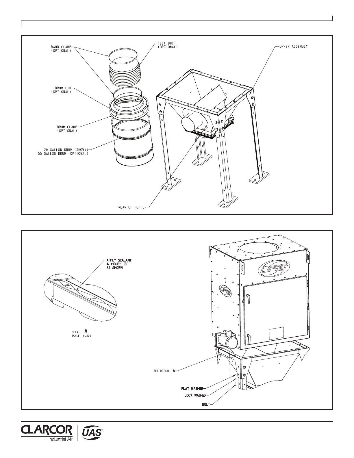
3.2 STANDARD EQUIPMENT ASSEMBLY
CRUSH AND ELECTROCUTION HAZARD
Use adequate safety measures when lifting and
assembling any heavy components. Consult your local
plant safety personnel for recommendations.
In preparing to attach the filter module to the hopper,
connect lifting slings and spreader bars to all filter
module lifting points with clevis pins. Use spreader
bars to distribute the load evenly. Location must be
clear of all obstructions, such as utility lines or roof
overhangs.
Remove all crating, strapping and hold-down bolts.
Locate all hardware bags, sealant and other assembly
materials provided with your unit.
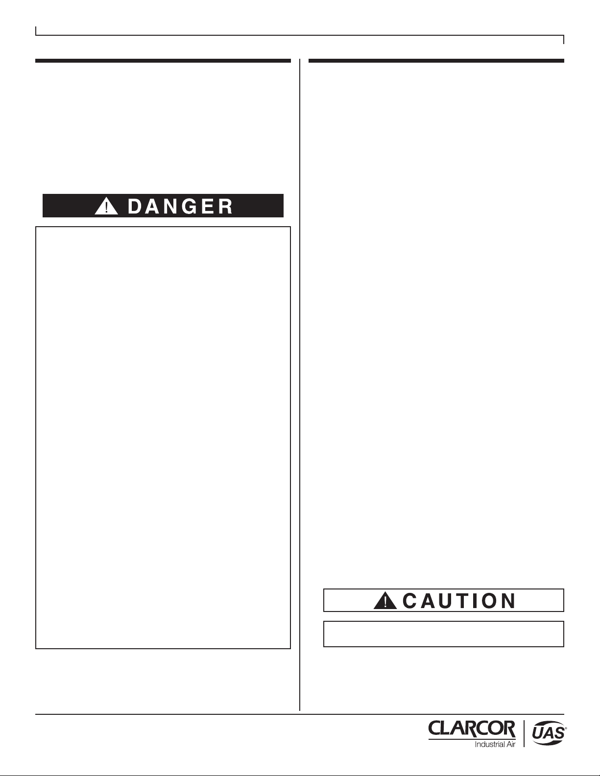
3.2.1 HOPPER ASSEMBLY
The SDC unit is designed to mount directly on top of the
hopper assembly. The hopper assembly consists of a
hopper bin, legs, sway-bracing (on larger models), optional
flex duct, hose clamps, 20 or 55-gallon drum, drum lid and
drum clamp. A hardware kit is also included to bolt the
filter module to the hopper.
3

Revised 10/15
SDC
Shaker Dust Collector
4
Revised 05/12
SDC
Shaker Dust Collector
Figure 2. Installation Details
61-10074-1
4Figure 2. Installation Details

Revised 10/15
SDC
Shaker Dust Collector
Revised 05/12
SDC
Shaker Dust Collector
3.2.2 SINGLE MODULE HOPPER ASSEMBLY
Assemble the four leg weldments to the hopper with the
shown hardware (refer to Figure 5; Detail A) and making
sure the base pads are oriented as illustrated. Secure
hopper/leg assembly to concrete mounting pad with
appropriate mounting hardware. Anchors should be
provided by customer or contractor according to local
codes.
3.2.3 MULTIPLE MODULE HOPPER ASSEMBLY
Position multiple hoppers side by side and bolt through
corner gussets as illustrated in Figure 6, Section A-A.
Locate and attach the leg weldments to the hopper
assembly per Figure 6, Detail A. Locate the diagonal
support braces and attach it to the hopper corner brackets
on left, right and rear sides of hopper referencing Figure 6,
Detail B making sure the base pads are oriented as
illustrated in Figure 6. Secure hopper/leg assemblies to
concrete mounting pad with appropriate mounting
hardware. Anchors should be provided by customer or
contractor according to local codes.
3.2.4 FILTER MODULE ASSEMBLY
Prior to mounting the filter module to the hopper assembly,
apply two ribbons of sealant to the hopper flange to create
a figure “8” pattern around the mounting holes. This
technique is shown in Figure 4 -Detail A.
Place the filter module onto the hopper assembly (as
shown in Figure 4). Drift pins may be required for aligning
holes between the two assemblies.
With the filter module still supported, use hardware (refer
to Figure 4) to bolt the hopper and filter module together.
Securely tighten all hardware at the filter module and
hopper. Check leg assembly sway braces (if applicable) to
ensure they are tight.
Disconnect lifting slings and spreader bars used for
installation.
Secure hopper/leg assemblies to concrete mounting
pad with appropriate mounting hardware. Anchors
should be provided by customer or contractor
according to local codes. Base pads are to be
oriented as illustrated in Figure 5 & 6.
3.3 ELECTRICAL INSTALLATION
ELECTRICAL SHOCK HAZARD
All electrical work should be performed by a qualified
electrician in accordance with local electrical codes.
Disconnect electrical power before installing or
servicing any electrical component.
General
Several types of standard electrical components can
be installed to control and monitor your dust collection
equipment. Aproperly sized fused disconnect or circuit
breaker should be installed to adequately protect the
equipment. Refer back to the nameplate on the
SDC unit or control enclosure to verify the control
configuration purchased with your unit for
proper sizing. Refer to Figures 9-11.
3.3.1 MOUNTING OF THE CONTROLS
The control enclosure require access at the beginning
and end of every shift of operation. Location should be
in a convenient, accessible area. The UAS control
enclosure contains the motor starters for both the
blower and shaker motors.
It is recommended that the controls be mounted on a
wall or pedestal subject to minimal vibration and
electrical noise. It is also suggested that the unit be
located in a convenient location with the controls as to
allow the customer easier access to wire to the unit
blower and shaker motors.
3.4 OPTIONAL EQUIPMENT ASSEMBLY
3.4.1 MAGNEHELIC®GAGE
Magnehlic gage is used to monitor the pressure drop
across the filter in your SDC unit. This helps you to
monitor the performance of your equipment and alerts
you to when the filter requires replacement.
The SDC unit cabinet comes with two pre-drilled holes
located on the left side of the cabinet for the pressure
taps and (4) dimples to locate and install the
Magnehelic gage. The holes are plugged when unit is
shipped.
Remove the snap in plugs using a flat head screw-
driver and install the (2) pressure taps in the SDC
panels. To tighten the pressure taps, access to the
inside part of the cabinet is required. Removal of the
filter cassette will be necessary to complete this
5

6
Revised 10/15
SDC
Shaker Dust Collector
6
Revised 05/12
SDC
Shaker Dust Collector
Figure 4. Unit to Hopper Assembly
Figure 3. Drum Assembly
61-10074-2
61-10074-3
6
Revised 05/12
SDC
Shaker Dust Collector
Figure 4. Unit to Hopper Assembly
Figure 3. Drum Assembly
61-10074-2
61-10074-3
Figure 4. Unit to Hopper Assembly

7
Revised 10/15
SDC
Shaker Dust Collector
7
Revised 05/12
SDC
Shaker Dust Collector
Figure 6. SDC-420-700 Hopper Assembly
Figure 5. SDC-140-350 Hopper Assembly
61-10074-12
61-10074-13
7
Revised 05/12
SDC
Shaker Dust Collector
Figure 6. SDC-420-700 Hopper Assembly
Figure 5. SDC-140-350 Hopper Assembly
61-10074-12
61-10074-13
Figure 6. SDC-420-700 Hopper Assembly

8
Revised 10/15
SDC
Shaker Dust Collector
8
Revised 05/12
SDC
Shaker Dust Collector
Figure 7. SDC-840-1050 Hopper Assembly
61-10074-14
Figure 7. SDC-840-1050 Hopper Assembly

Revised 10/15
SDC
Shaker Dust Collector
Revised 05/12
SDC
Shaker Dust Collector
installation. Drill out the (4) locating dimples (closest to
the door side) to allow clearance for 1/4” supplied
hardware (5/16 drill bit is recommended). Access the
inside of the cabinet to tighten down the bracket
hardware. Install the gage into the bracket using the
supplied hardware.
After the pressure taps are installed, run 1/4” tubing
from the SDC cabinet to the Magnehelic gage and
connect to the dirty air side of the cabinet to the
pressure port marked “High” and the clean air side to
the pressure port marked “Low”. Take care not to kink
the tubing during installation.
3.4.2 EXPLOSION VENTING
The SDC unit can be built to accommodate applications
where explosion vents are required. All explosion
vented installations should comply with the guidelines
described in NFPA 69. Consult your local authorities or
insurance provider for any specific regulations that may
apply to your location.
Design changes are required such as strengthening of
the cabinet and the filter access doors. The explosion
vent(s) are mounted on the rear of the cabinet or the
opposite side of the filter access doors. Placement of
the unit and the vent orientation should be in
accordance with the appropriate national safety
guidelines in NFPA 69. Figure 8 illustrates a typical
explosion vented installation along with the re-enforced
filter access door(s).
Refer to UAS explosion vent manual (Part Number
44-10284-0001) for further installation details.
Placement of the unit and the vent orientation
should be in accordance with the appropriate
national safety federal and local regulations.
Figure 8. Typical Explosion Vented Unit
4. OPERATION
Place the unit disconnect switch in the off position,
and lock out all electrical power to the dust
collector prior to performing service work.
Prior to unit start-up, all installation set-up
instructions must be completed as specified by this
manual. Refer to Section 3.
4.1 START-UP CHECKLIST
1. Inspect the installation area and make certain that
no tools, parts, etc., have been left anywhere on or
inside the SDC unit. Check discharge area(s) on
unit to make sure they are free from obstructions.
2. Check that all accessories are properly and securely
installed, including the hopper assembly and drum.
Ensure that there are no air leaks in the ducting or
hopper connections.
3. Turn power on at the source (fused disconnect).
4. Make sure the selector switch titled “Clean” is in the
off position, pressing the “Start Fan” button and then
the “Stop Fan & Clean” button.
5. The blower should be checked for proper rotation.
The wheel should be rotating clockwise when
looking at the drive side or top of the motor. If the
blower is rotating in the opposite direction,
disconnect the power to the unit and interchange
any two wires from the blower motor within the SDC
junction box. Refer to Figure 9.
NOTE:Proper blower rotation is required to
move the designed amount of airflow. Ablower
rotating in the incorrect direction will only move
approximately 40% of design airflow.
6. The shaker motor should also be checked for proper
rotation with the correct direction being clockwise
from the drive side or top of the motor. If the motor is
rotating the wrong direction, some threaded fittings
may have a tendency to loosen during normal
operation. Disconnect power to the unit and
interchange any two wires from the shaker motor
within the SDC junction box. Refer to Figure 9.
61-10074-7
9

10
Revised 10/15
SDC
Shaker Dust Collector
Figure 9. Wiring Diagram
04-2611-01A

11
Revised 10/15
SDC
Shaker Dust Collector
Figure 10. Interconnect Diagram
04-2610-01

Revised 10/15
SDC
Shaker Dust Collector
Revised 05/12
SDC
Shaker Dust Collector
Revised 05/12
SDC
Shaker Dust Collector
7. You are now ready to begin using the unit for
production. Press the
“
Start Fan” button on the
control panel and turn the “Clean” button to the
on position.
IMPORTANT
It is recommended that you document the static
pressure in critical locations throughout your process
when the filters are clean and your system is running
as intended. This will aid in troubleshooting your
installation and allow you to accurately predict when
it is time to change your filters.
Initially, some dust may discharge from the unit and
may last for several minutes. As the filters season and
begin to build up a dust cake, the discharge should
remain visibly clear.
If you are operating the unit in short intervals, it may be
necessary to leave the cleaning button in the off
position during the first several intervals until a
sufficient dust cake is obtained.
4.2 SHUT-DOWN AND FILTER CLEANING
Press the “Stop Fan & Clean” button on the control
panel with the selector switch in the “Clean” position.
This will place the SDC off line and initiate a
cleaning sequence. The unit will pause for
approximately 70 seconds to allow the blower to coast
down to a speed where it is no longer pulling a
significant amount of air through the cabinet.
At the end of the 70 seconds, the shaker motor will
be on line. The bags will be shaken at a high frequency,
low amplitude vibration for 35 seconds, and will
dislodge collected dust from the bags. The dust will
then gravitate to the hopper and collect in the drum
below the unit.
If required, this sequence can be repeated by pressing
the “Stop Fan & Clean” button again. This will initiate a
cleaning sequence after a 70-second delay.
5. SERVICE
Before servicing dust collector:
• Wear appropriate protective clothing.
• Disconnect electrical power to the unit and
control panel.
• Collected dust may be hazardous. Consult
proper authorities for handling and disposal.
• Collected dust may be a potential fire hazard.
Welding, grinding or operations involving open
flames should not be performed without fire
protection measures in place. Refer to Section
1 of this manual for additional safety
precautions.
• Disposal of collected dust must be according to
federal, state and local regulations and all
appropriate authorities.
5.1 FILTER REMOVAL AND REPLACEMENT
To remove the SDC filter assembly(s), first open the
filter access door. The filter is held in place by a cambar
mechanism located on each side of the filter cassette.
This mechanism is illustrated in Figure 11.
When in the locked or sealed position, the cambar
handles will be in a horizontal position towards the
center of the filter assembly. To unlock the filter, each
cambar handle must be rotated down 90 degrees.
The filter will become loose and drop into a position
from which it can be removed from out of the unit.
Figure 11.Filter Sealing Mechanism
61-10074-10
12

Revised 10/15
SDC
Shaker Dust Collector
Revised 05/12
SDC
Shaker Dust Collector
Revised 05/12
SDC
Shaker Dust Collector
Check that all hardware is tight, including the
set-screws attaching the hub to the motor shaft, the
shoulder bolt that is threaded into the hub and the nuts
that secure the drive shaft to the shaker fingers. If
hardware requires tightening, use a thread locker to
secure. Inspect all bushings for signs of wear. Also
inspect the rubber grommet that seals the mechanism
to the cabinet for tears or excessive wear.
If it is not time to replace the bags, inspect them for
wear or abrasion around the shaker fingers.
It is recommended that you grease shaker motor every
3,600 hours with high grade gall bearing grease
(i.e. Shell Dolium or Chevron SRI-2).
5.4 SERVICING THE BLOWER
ELECTRIC SHOCK HAZARD
All electrical work should be performed by a qualified
electrician in accordance with local electrical codes.
Disconnect electrical power before installing or
servicing any electrical equipment.
Periodically inspect the fan blades to ensure proper fan
life. Clean the fan blades of any deposited material.
Grease the blower motor every 3,600 hours with high
grade gall bearing grease (i.e. Shell Dolium or
Chevron SRI-2).
Filters can weigh in excess of 125 lbs. Please use
extreme caution when removing from cabinet.
Slide the cassette from the cabinet, as shown
in Figure 12. This will require two people
(or a fork truck), due to the weight of the filter and the
collected dust. When the cassette is removed from the
cabinet, inspect the gasket on the underside of the
tubesheet for damage. If there are cracks or tears it is
recommended that the gasket should be replaced.
Refer to Section 8 for replacement parts.
To replace the filter, remove the inserts from each
pocket as shown in Figure 12. When this is complete,
release the snap band that secures the filter to the
cassette and then lift the filter up through the support
rods and free of the cassette.
Reverse the above directions to install the new filter.
Take care to make sure the filter fabric seats properly in
the filter frame. As the filter cassette is slid into the
cabinet, thread each pocket through the shaker
mechanism teeth. Make sure the wear strips, located
on the bottom-center of each pocket, are in contact with
the shaker fingers.
5.2 DUST REMOVAL
As the SDC system cleans, dust collects in the drum.
The dust should be removed periodically to prevent
re-entrainment, eliminating dust piling up into the
hopper section. Your application will determine the
appropriate intervals between emptying the drums.
To remove the drum barrel, disengage the drum clamp
and lift up the drum lid.
Reverse these directions to replace the drum barrel.
5.3 SERVICING THE SHAKER MECHANISM
On a quarterly basis, remove the shaker mechanism
cover plate and inspect the moving parts of the shaker
mechanism. Refer to Figure 12.
13

Revised 10/15
SDC
Shaker Dust Collector
16
Revised 05/12
SDC
Shaker Dust Collector
Revised 05/12
SDC
Shaker Dust Collector
Figure 13. Filter Replacement
61-10074-11
14 Figure 12. Filter Replacement

15
Revised 10/15
SDC
Shaker Dust Collector
17
Revised 05/12
SDC
Shaker Dust Collector
Revised 05/12
SDC
Shaker Dust Collector
6. TROUBLESHOOTING
Motors for Blower or
Shaker Will Not Start
Supply Power Not Operational Check input power to motor circuits for proper
voltage on all legs.
Check and correct internal motor wiring for
proper connections based on the incoming
line voltage. Check control voltage power
supply (i.e. fuses, transformer, overloads etc.).
Improper Electrical Wiring
Dust Emissions From
Clean Air Discharge
Filter Not Installed Properly Check to make sure cambars are in the
upright and locked positions. Inspect gasket
on underside of tubesheet for damage.
Allow filters to seed during normal operation.
Emissions should dissipate after several hours
of dust loading.
New Filters are Not Seasoned
Insufficient Airflow Blower Rotation is Reversed All blower packages on the SDC should be
rotating clock-wise when looking at the drive
side of the motor.
Check to make sure the filter access door of
the cabinet is tightly closed. Check the drum
connection and ductwork between the process
and collector for leaking connections.
Leak Downstream of Collection Hood
The filters either need to be cleaned or are at
the end of their useful life.
Filters Plugged
Continual, Excessive
Pressure Drop
Shaker Cleaning System Not Functioning
Properly
Remove shaker mechanism access panel and
inspect. Make sure all connections are tight
and the drive shaft is securely attached to the
shaker fingers.
Empty drum and clean out hopper.Dust Storage Drum is Full
The filters either need to be cleaned or are at
the end of their useful life.
Filters Plugged
Increase air inlet and/or duct size to minimize
static pressure losses. Follow ductwork design
methods as listed in
Industrial Ventilation
Manual
by American Conference of
Governmental Industrial Hygenists.
Air Inlet and/or Ducting is Undersized
PROBLEM POSSIBLE CAUSE RECOMMENDED SOLUTIONS

Revised 10/15
SDC
Shaker Dust Collector
18
Revised 05/12
SDC
Shaker Dust Collector
7. WARRANTY REPLACEMENT PARTS
ITEM NO. PART NO. PART DESCRIPTION
1 10-12510-0001 Bronze Bushing
2 15-0202 Flex Duct
3 15-0233 Band Clamp
4 22-10031-0001 Motor, 1/3hp, 230/460/3/60, 1140rpm, 56C
5 30-10055-0500-W Screw
6 30-10072-0001 1-1/4-12 Half Hex Nut
7 30-10071-0001 Shaker Shoulder Bolt
8 32-10045-0001 Shaker Drive Bushing (fixed end)
9 33-10086-0001 Filter Insert (SDC-70)
33-10086-0002 Filter Insert (SDC-140, 210, 420)
33-10086-0003 Filter Insert (SDC-280, 350, 560, 700, 840, 1050)
10 35-10019-0001 Shaker Hub
11 35-10031 Shaker Drive Shaft
12 35-10032 Shaker Connector
13 35-10033 Shaker Drive Shaft Long
14 39-10048 Clevis Pin
15 42-10060-0140 SDC-140 Tubesheet Gasket
42-10060-0210 SDC-210 Tubesheet Gasket
42-10060-0280 SDC-280 Tubesheet Gasket
42-10060-0350 SDC-350 Tubesheet Gasket
16 45-10072 Door Gasket
17 45-10022-0020 20 Gal. Drum Lid Clamp
45-10022-0055 55 Gal. Drum Lid Clamp
18 45-10034-0020 20 Gal. Alum. Drum Lid
45-10034-0055 55 Gal. Alum. Drum Lid
19 Consult UAS Fan Package
20 Refer to Unit Label Filter Assembly
For replacement parts not listed in the table below, please contact UAS Customer Service at 1-800-252-4647 for additional
information. To assure optimum performance of your dust collection equipment, replacement filter bags should be purchased
from United Air Specialists.
16
Table of contents
Other UAS Dust Collector manuals
Popular Dust Collector manuals by other brands

Grizzly
Grizzly G0440 owner's manual

Grizzly
Grizzly G1028Z/G1029Z owner's manual

Elektra Beckum
Elektra Beckum SPA 2000 Betriebsanleitung

Dustless
Dustless CutBuddie LT owner's manual

Central Machinery
Central Machinery 61808 Owner's manual & safety instructions

General
General 10-030CF M1 Setup & operation manual