ubicquia ubismart AQM+ User manual

© 2022 Ubicquia, Inc.
1
Installation Guide
Guía de instalación
UbiSmart™ AQM+ Unit
Unidad UbiSmart™ AQM+
*ES: NOTA: UbiSmart AQM+ solamente funciona
cuando esta conectado con un UbiCell™o UbiHub™.
*EN: NOTE: UbiSmart AQM+ device only functions
when paired with UbiCell™or UbiHub™.
Captive Mounting Screw
Tornillo Cautivo
Mounting Bracket
Soporte de Instalacion
Connector + 20 AWG Cable (40ft / 12m)
Conector + Cable de Grosor de 20 AWG
(40ft / 12m)
Lever Nut Connector (2X)
Conector para Empalmar el Cable (2X)
Heat Shrink Butt Connector
Conector Termoretráctil
Required Materials
. Tamper Resistant T15 Driver
. Concrete screws (x2) or up to
1/2 inch bands (x2)
. Other tools required depending
on bracket installation method
Herramientas Necesarias
. Destornillador Torx T15
. Tornillos para concreto (x2) para
cintas de hasta ½”
. Se requieren otras herramientas
dependiendo del método de
instalación del soporte

© 2022 Ubicquia, Inc.
2
Based on EPA
recommendations:
Horizontal & vertical distance from
supporting structures > 1m
Distance from trees > 20m
Distance from highway > 50m
Based en recomendaciones
de EPA:
La distancia horizontal y vertical
de las estructuras de soporte > 1m
Distancia de árboles > 20m
Distancia de calle > 50m
1
EN: Mounting Height. Ubicquia
recommends the UbiSmart AQM+
be mounted 10ft / 3m above ground.
ES: Altura de Montaje. Ubicquia
recomienda montar el Ubismart
AQM+ a 10 pies / 3m sobre el suelo.
2
EN: Ubicquia provides a 40 ft
connection cable with connector.
If more cable is needed, use a 20
AWG cable with a PVC, UV stable
jacket.
ES: Ubicquia provee un cable de
40 pies incluyendo el conector. Si
necesita más cable, recomendamos
utilizar un cable de cobre aislado
de calibre 20 con una camisa de
PVC y protección contra rayos
ultravioleta (UV).
3
EN: Installing with UbiCell. Prior to
beginning the wiring process, ensure
that the UbiCell part number begins
with UBC-20 or higher.
ES: Version UbiCell. Antes de
comenzar el proceso de cableado,
asegúrese que la version de UbiCell
es 2.0 o mayor.
10ft
(–)
(+)
5
EN: Concrete/Wood Pole. The
cable should be secured externally
down the length of the electrical
pole.
ES: Poste de
Concreto/Madera.
El cable debe estar asegurado
externamente en toda la longitud
del poste eléctrico.
EN: Metal Pole. The cable should
be run inside the pole. Drill hole at
UbiSmart AQM+ mounting location
(height: 10ft / 3m) and feed the free
end of the cable through drilled
hole using appropriate equipment.
ES: Poste de Metal. El cable debe
correr por dentro del poste. Perfore
un oricio a la altura de instalación
del UbiSmart AQM+ y pase el
cable por ese oricio utilizando
un pasacables apropiado (no está
incluido).
6
EN: When opening the luminaire
locate the ORANGE (-) and
BROWN (+) wires connected to
the NEMA driver. DO NOT USE the
ORANGE & BROWN connected to
the LED driver.
ES: Cuando abra la lampara,
localice los cables NARANJA (-)
y MARRÓN (+) conectados al
controlador NEMA. NO UTILICE
los cables NARANJA y MARRÓN
del controlador de LED.
BROWN (+)
MARRON (+)
4
EN: Unscrew the captive screw
and remove the bracket from the
back of the UbiSmart AQM+.
ES: Destornille el tornillo cautivo
y remueva el soporte de la parte
trasera del UbiSmart AQM+.
ORANGE (-)
NARANJA (-)
T15

© 2022 Ubicquia, Inc.
3
7
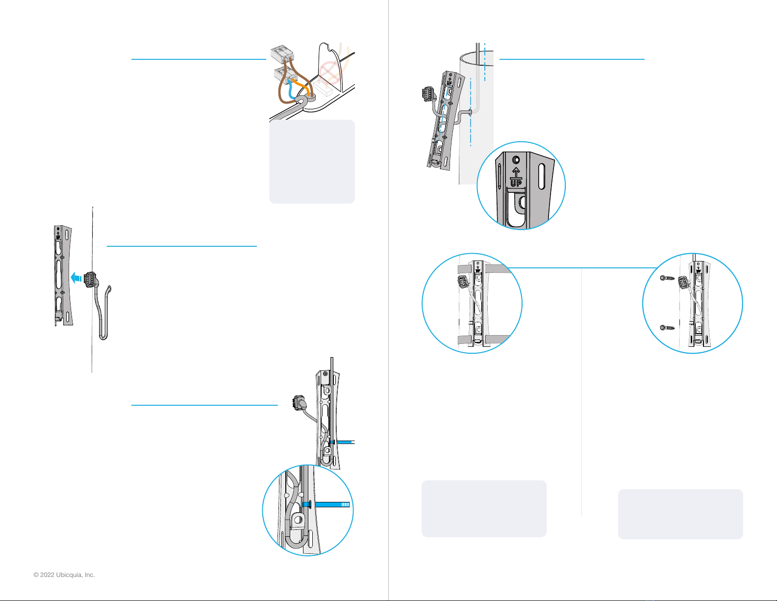
EN: Using the 40ft / 12m cable
referenced in step 2, connect the
BROWN wire to the BROWN cable
(+), and the ORANGE wire to the
BLUE cable (-) using a standard
lever nut connector.
ES: Usando el cable de 40 pies
/ 12 m mencionado en el paso
2, conecte el cable MARRÓN a
el cable MARRÓN (+) y el cable
NARANJA al cable AZUL (-)
usando un conector para empalmar
el cable.
8
EN: Feed the connector through
the opening in the bracket. Ensure
there is up to 2 inches of service
loop cable between bracket and
connector.
ES: Pase el conector por la
apertura del soporte. Asegurase
de que haya 2 pulgadas de cable
colgante de servicio entre el
soporte y el conector.
9
EN: Align the connected cable
down the center of the bracket to
create a drip loop. Secure with a
zip tie, and cut the zip tie excess
when complete.
ES: Alinea el cable conectado por
el centro del soporte para crear
un bucle de goteo. Asegúrelo bien
con un cintillo plástico, y corte el
exceso al terminar.
EN: BE SURE TO
NOTE THE WIRE
POLARITY FOR
STEP 9
ES: ASEGÚRESE
DE OBSERVAR LA
POLARIDAD PARA
EL PASO 9
10
EN: Use the UP indicator to
correctly orient the mounting
bracket vertically, parallel to the
pole.
ES: Use el indicador “UP” para
orientar correctamente el soporte
verticalmente, paralelo al poste.
EN: Metal Pole. Two 1/2 inch
bands (not included). Thread the
two bands through the slots in the
bracket. Place the bracket against
the pole and tighten the metal
bands until secure.
ES: Poste de Metal. Dos bandas
de 1/2 pulgada (no incluidas).
Instalar las dos bandas a través de
las ranuras del soporte, conéctelo
al poste, y apriete hasta que estén
bien sujetas.
EN: Concrete/Wood Pole.
Two 1/4” concrete screws (not
included). Align the screws and
tighten until at against the surface
of the bracket. If necessary, use a
wrench or drill.
ES: Poste de Concreto/ Madera.
Dos tornillos para concreto (no
incluidos). Usando una llave para
tuercas o un taladro, alinea los
tornillos y apriételos hasta que
queden planos en la supercie del
soporte.
11
NOTE: When tightening, ensure
the bracket does not crush the
cable.
NOTA: Al apretar, asegúrese de
que el soporte no aplaste el cable.
NOTE: Do not over-torque the
screws.
NOTA: No apriete demasiado los
tornillos.

© 2022 Ubicquia, Inc.
4
12
EN: Once the bracket is secured,
ensure that the cable is pulled
through, and is not pinched by the
bracket.
ES: Una vez instalado el soporte,
asegúrese que el cable pase a
través del soporte, y el cable no esté
aplastado por el soport.
13
EN: Toe in the bottom of the
UbiSmart AQM+ into the bracket.
ES: Coloque el Ubismart AQM+
enganchando la parte de abajo
primero al soporte instalado
previamente.
15
EN: Rotate the device upwards into
the locked position.
ES: Gire el dispositivo hacia la
posición de cerrado.
14
EN: Plug in the connector and
securely connect the wire grommet
into the UbiSmart AQM+.
ES: Enchufe el conector y conecte
rmemente el pasacables en el
UbiSmart AQM+.
16
EN: Fasten the UbiSmart AQM+
to the bracket with the captive
screw, using a Tamper Resistant
T15 Driver.
ES: Fije el UbiSmart AQM+ al
soporte, apriete el tornillo cautivo
con el destornillador T15 especial
(contra alteraciones).
17
EN: The UbiSmart AQM+
installation is complete.
ES: La instalación del UbiSmart
AQM+ se ha completado.
T15
18
EN: After powering up device for
the rst time, the UbiSmart AQM+
takes ~ 45 minutes for sensor
values to be displayed on UbiVu.
ES: Después de encender el
aparato por primera vez, el
UbiSmart AQM+ tarda sobre 45
minutos para que los valores del
sensor se muestren en el UbiVu.

© 2022 Ubicquia, Inc.
© 2022 Ubicquia, Inc. All rights reserved. Patent(s) pending. Public use approved.
Todos los derechos reservados. Pendiente de patente. Aprobado para uso publico.
2064 v3 April 2022
FCC statement
This device complies with Part 15 of the FCC Rules. Operation is subject to the following
two conditions: 1) This device may not cause harmful interference, and 2) This device
must accept any interference received, including interference that may cause undesired
operation.
Changes or modications not expressly approved by Ubicquia, Inc. could void the user’s
authority to operate the equipment.
NOTE: This equipment has been tested and found to comply with the limits for a Class
B digital device, pursuant to part 15 of the FCC Rules. These limits are designed to
provide reasonable protection against harmful interference in a residential installation.
This equipment generates, uses and can radiate radio frequency energy and, if not
installed and used in accordance with the instructions, may cause harmful interference
to radio communications. However, there is no guarantee that interference will not occur
in a particular installation. If this equipment does cause harmful interference to radio or
television reception, which can be determined by turning the equipment o and on, the user
is encouraged to try to correct the interference by one or more of the following measures:
• Reorient or relocate the receiving antenna.
• Increase the separation between the equipment and receiver.
• Connect the equipment into an outlet on a circuit dierent from that to which the
receiver is connected.
• Consult the dealer or an experienced radio/TV technician for help.
EN: QUESTIONS? CONTACT UBICQUIA SUPPORT:
Phone: +1-(954)-678-6191
ES: ¿PREGUNTAS? CONTACTE ATENCIÓN A CLIENTES DE UBICQUIA:
Teléfono: +1-(954)-678-6191
www.ubicquia.com
Table of contents
Other ubicquia Accessories manuals
Popular Accessories manuals by other brands

Woodstock
Woodstock SHOP FOX W1693 instruction sheet

Julabo
Julabo SC 2500a operating manual

S+S Regeltechnik
S+S Regeltechnik KINASGARD RBWF Operating Instructions, Mounting & Installation

S+S Regeltechnik
S+S Regeltechnik HYGRASREG AFTF-35 Operating Instructions, Mounting & Installation

Bohn
Bohn BMA Technical guide

shelolab
shelolab SMI1E Installation and operational manual

Sunbeam
Sunbeam Safe & Sound Instruction booklet

funtec
funtec Fun Beach Set Setup manual

Morphy Richards
Morphy Richards WASHABLE HEATED UNDERBLANKET - REV 1 manual

Champion Essick
Champion Essick RWC44 manual

Wenglor
Wenglor ShapeDrive G4 MLAS 1 Series operating instructions

Leviton
Leviton enocean alliance WSWDR-10W Instruction