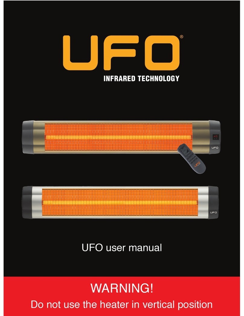
UFO Star Series User manual

USER MANUAL & CERTIFICATE OF WARRANTY
MANUAL DE USUARIO & CERTIFICADO DE GARANTÍA


USER MANUAL &
CERTIFICATE OF WARRANTY
WARNING!
DO NOT USE THE HEATER IN VERTICAL POSITION
Please read the instructions before installing the device

ENGLISH
Table of Contents
2
1. Introduction...................................................................................................................................3
2. Safety.............................................................................................................................................4
2.1. Electrical Connections......................................................................................................4
2.2. Safe Distances and Proper Orientation..............................................................................5
3. Installation..........................................................................................................................5
3.1. Installation Guidelines – Optimal Placement...........................................................5
3.2. Installation Guidelines – Recommended Clearances........................................................7
3.3. Installation Guidelines - Parts Included........................................................................8
3.4. Installation Instructions – Mounting Your Heater.........................................................10
4. Operating Instructions...........................................................................................................11
4.1. UFO STAR Series - Models Equipped with Thermostatic Control.................................11
4.2. UFO UK Series - Models with Remote Control...................................................................12
4.2.1. Remote Control Description..............................................................................12
4.2.2. Remote Control Operating Instructions.........................................................................13
4.2.3. The LED Panel...................................................................................................13
5. Technical Data – Specifications and Coverage Information.........................................................14
5.1. Star Model Specifications...........................................................................................14
5.2. UK Model Specifications........................................................................................16
5.3. Coverage Information...........................................................................................18
6. Cleaning and Maintenance.......................................................................................19
7. Original Filament Definition..............................................................................................19
8. Warranty Information and Company Contact..........................................................................20

1. Introduction
ENGLISH
3
Thank you for choosing UFO to meet your heating needs. This manual is designed for our
Star and UK line models.
You have purchased a high quality, UFO Infrared Heater. In order to ensure that your UFO
heater provides efficient, safe and comfortable heat, please take the time to review this user
manual.
Before installing your heater, review the safety information found in Section 2. Strict adherence
to these guidelines is necessary to prevent personal injury or property damage.
Section 3 reviews essential installation and assembly instructions, containing placement and
orientation guidelines that are extremely important to a safe and efficient installation.
All UFO brand products are registered TUV compliant. This certification is
recognized by OSHA and is accredited by OSHA to complete all the tests
required for the US market.
USA Office:
UFO Heaters USA
Suite #226
112 W. 9th Street
Los Angeles, CA 90015 USA
(213)553-8440
(213)553-4573
http://www.ufoheaters.com
Manufacturer: UFO Isikla Isitma
Sistemleri San. ve Tic. Ltd. Sti.
Akçaburgaz Mah. 72. Sok. No:17
Esenyurt / Istanbul - TURKEY
Please keep this manual in a safe place for future reference.

ENGLISH
4
2. Safety
The following guidelines will allow you to enjoy your UFO heater while minimizing the
possibility of personal injury or property damage.
2.1 Electrical Connections
• Check whether your heater and power cord are damaged before operating your heater.
In case of damage, do not operate your heater and contact to an authorized technical service.
• Connect your UFO heater to a properly rated circuit.
A minimum of 15 amps is recommended. Many household
circuits are rated at 15 amps, but if other appliances are
on the same circuit, the breaker may trip. If this is the
case, consider moving your heater to a higher-rated circuit,
either by using a properly rated extension cord (min. 14
awg.), or by having the circuit rewired to higher capability.
Ensure that the grounding capability of your heater’s power
cord is maintained. Never use a three-prong to two-prong
adapter without securing an additional grounding location.
• When using your UFO heater in kitchens, baths or exterior application areas (where
approved), use only an approved GFCI (Ground Fault Circuit Interrupter) outlet.
Never locate heater where it may fall into a bathtub or other water container.
• Try to orient your heater so that the power cord, plug and/or outlet are not within the
direct heating area.
• Do not allow the power cord to rest on the housing of your heater.
• Avoid the use of an extension cord because the extension cord may overheat and cause
risk of fire. However if you have to use an extension cord, the cord shall be minimum 14
AWG. And not rated less than 3000 watts.
• Do not run cord under carpeting- Do not cover cord with throw rugs, runners, or the like.
Arrange cord away from the traffic area and where it will not be tripped over.
• Always unplug the heater if it is not being used.
• Unless there is sufficient circuit protection (an integral over current/surge breaker) do not
use multiple plugs or extension cords.
• If you are using an outlet strip, it must be rated at 15 amps and include a breaker/reset
function.
Grounding type
wall receptacle Do not under any
cercumstances cut,
remove, or bypass
the grounding prong
from this plug.
Power supply cord
with 3-prong
grounding plug

2.2 Safe distances and Proper Orientation
ENGLISH
5
• UFO heaters are designed to be operated in the HORIZONTAL position only. Always install
your heater so that there is no more than 5° deviation from level (See Illustration, Page 8).
Operating the heater in a tilted position will cause heat build-up, shorten the life of your
heater and create an unsafe condition.
• The distance of your heater from the ground should be a minimum 1,8 meters (6 feet).
• Never install your heater on a combustible surface (plastics, nylon, cardboard etc.)
• Keep combustible materials, such as furniture, pillows, bedding, papers, clothes and curtains
at least 1 meter (3.5 feet) from the front of the heater and keep them away from the sides.
• Do not operate within 7,6 meters (25 feet) of flammable material (gasoline, alcohol etc.)
• Do not cover your heater and do not hang any clothing over the heater or do not place
any clothing on or near the heater.
• Supervision is needed when this product is used anywhere near children. The heater is not
intended for use by children or other persons without assistance or supervision if their
physical, sensory or mental capabilities prevent them from using it safely.
• This heater is hot in use. To avoid burns do not touch to hot surfaces.
Refer to the illustrations and accompanying table on Page 7 for guidelines on the safe
placement of your heater.
3 Installation
Before installing your UFO heater, consult the following tables and diagrams to determine
the optimal orientation and to ensure that safe distances are maintained.
3.1 Installation Guidelines – Optimal Placement
UFO heaters use infrared energy to transmit heat directly onto objects and people. Unlike
forced-air or baseboard convective systems, UFO infrared heat is radiated onto an object, and
that heat is absorbed only by that object. The air is not heated and the heat will not migrate
to objects you don’t want to heat. Along those same lines, unless you position your heater
correctly, it will not perform as expected, and its efficiency will be diminished.

ENGLISH
6
WRONG RIGHT
WRONG RIGHT
WRONG RIGHT
• Ensure that the radiant heat is not directed out windows or doorways. Infrared heat will
pass through glass and wastes heat on objects that are outside.
• Position your heater so that it warms your work/living area, not the air above or below it.

ENGLISH
7
3.2 Installation Guidelines – Recommended Clearances
It’s also important to remember that infrared heat will reflect off of shiny or bright
surfaces. Heat will be reflected off of mirrors or tile surfaces and fall upon objects you
may not intend to heat.
Although infrared heat does not use a flame or a heating grate, significant heat can be
developed near the filaments and along surfaces on the heater housing. The heater should
not be installed on flammable wall coverings or on surfaces that will deform or discolor when
subjected to heat.
In addition, your heater should be installed
with the following considerations:
• Minimum 71 inches (180 cm) from the
ground when installed on the wall and
95 inches (240 cm.) from the ground
when installed to the ceiling.
• Minimum 16 inches (40 cm) from the
walls when installed on the wall and
28 inches (70 cm.) from the walls when
installed to the ceiling.
• Minimum 40 inches (1meter) from
curtains or other decorations.
• Do not place combustible materials closer than 40 inches (1 meter) in front of the heater.
• Do not place explosive materials closer than 25 feet (7,6 meter) in front of the heater.
WRONG RIGHT
Floor
Min. 40 cm
(16 in)
a
Min. 180 cm
(71 in)
Ceiling
Wall
Min. 240 cm
(95 in)
Min. 70 cm
(28 in)
Wall
Floor
Ceiling
Min. 70 cm
(28 in)
Wall
Ceiling
16 inches 24 inches 28 inches
1800
1800 - 2800 2800
a
Power
Watt

ENGLISH
8
• IMPORTANT!! ALWAYS install your heater in a horizontal fashion.
5º or more slope
WRONG RIGHTWRONG
3.3 Installation Guidelines - Parts Included
Your UFO heater comes completely assembled and is shipped with the necessary
hardware to install your heater on the wall or ceiling. Check through the parts list and
ensure that all necessary parts are on hand before beginning. Contact UFO if parts are
missing or broken.
Install your heater so that there is no more than 5° deviation from level (See Illustration).
Operating the heater in a tilted position will cause heat build-up, shorten the life of
your heater and create an unsafe condition.

ENGLISH
9
18
21
24
25
26
28
29
32
UFO HEATER PARTS LIST
Part # Code
150.03.027
150.05.003
150.05.011
150.05.021
150.05.030
150.05.012
150.02.012
150.03.008
Code
Brackets
4.8mm X 7.5mm
Steel Screw
8.4mm x 24mm x 2mm
Washer
8mm x 13mm Bolt
8mm Cap Nut
5mm x 40mm
Mounting Screw
8mm Plastic Anchor
Wrench
4
2
2
2
2
4
4
1
Qty Image

ENGLISH
10
3.4 Installation Instructions – Mounting Your Heater
Figure 1
Figure 3
Figure 2
1- Determine the location where the brackets (Part #18) will be installed on the wall and drill
four 5/16” diameter holes according to the distances shown in Figure-1.
2- Insert the anchors (Part #29) into the holes.
3- Mount two of the L-shaped bracket legs on the wall using the supplied 40mm screws
(Part #28).
4- With the small (open end) wrench, attach the other L-shaped bracket legs to the heater
as shown in figure-2. Use the two 7.5mm screws (Part #21). The female threads are built
into the heater housing.
5- Attach the heater brackets to the wall brackets using the 8mm bolts (Part #25), the 8mm
cap nuts (Part #26) and the washers (Part #24) as shown in Figure-3. Tighten using the
large end (box end) of the supplied wrench. (Part #32)

ENGLISH
11
6- You can adjust the heater at between a 0 – 45 degree angle in order to achieve optimal
heating effect (see Figure 4).
7- Before operating the unit, recheck all of the screws and bolts to ensure they are tight.
NOTE: Be sure to route the electrical cord so that it doesn’t contact the heater housing.
Figure 4
4 Operating Instructions
Depending on the model, your UFO heater provides controls that allow you to adjust its
operation for consistent comfort levels and increased energy savings.
4.1 UFO STAR --- Models Equipped With Thermostatic Control
UFO STAR Models are equipped with a thermostat
that will adjust the heater’s power output to
maintain the desired comfort level. The heater
will operate constantly at any of the positions.
Selecting the appropriate position will allow you
to set the heat output to the desired comfort level
for your room.
The heater will not operate with the thermostat
set at the lowest (OFF) position, but it should be
disconnected when not used for long periods of
time.

ENGLISH
12
4.2 UFO UK Models with Remote Control
The UK model units come with a remote control that allows you to control the heater’s power
settings and program various timer operations. Insert two “AAA” batteries into the remote
before use. Always use new alkaline batteries, and remove the batteries when the heater will
not be used for long periods.
4.2.1 Remote Control Description
Refer to the following graphic and the accompanying descriptions (section 4.2.2.) when
programming your remote/heater.
9
1
2
5
8
7
6
4
3
1. On / Off
Turns the heater on or off or puts heater on
standby.
+ -
2. / (Program Up / Down)
Adjusts program settings..
3. Clock
Sets the time.
4. Timer On
Switches on the heater in standby mode.
5. Timer Off
Switches off the heater in preset time and
starts stand by mode.
6. Sleep
Switches off the heater in preset time
7. Everyday
Makes the heater operate in preset
parameters everyday.
8. Cancel
Cancels all settings.
9. LCD (Liquid Crystal Display)
Displays the settings of the remote control
and related indicators.

ENGLISH
13
4.2.2 Remote Control Operating Instructions
Power the unit on by pressing the ON/OFF button.
When the power is initially turned on, the UP/DOWN arrows control the power setting of the
heater. Adjust the heater to the desired power level before continuing with the timer settings.
When you press the CLOCK button, the UP/DOWN arrows are used to set the clock. Pressing
the arrows repeatedly accelerates or slows down the change interval.
Pressing the TIMER ON button lets you use the UP/DOWN arrows to designate a time when
you want your heater to come on. Pressing the TIMER ON button again saves that setting.
Pressing the TIMER OFF button lets you use the UP/DOWN arrows to set the time when you
want your heater to turn off. Pressing the TIMER OFF button again saves that setting.
Once the TIMER ON and TIMER OFF settings have been entered, you can press the EVERYDAY
button to repeat the on and off times on a daily basis. Unless cancelled or otherwise modified,
the TIMER ON and TIMER OFF settings you enter will be repeated every day. The unit must
be in STANDBY mode (plugged in) for timer operations to occur. The LED screen on the heater
body will flash continuously when any program is set via the remote control.
Pressing the SLEEP button allows you to operate the heater for a designated amount of time
before shutting off. Using the SLEEP function will override current TIMER ON/OFF programmed
settings, but will not cancel future programmed operations.
Pressing the CANCEL button clears each program entry. Wait three seconds between presses
to go back through your times.
4.2.3 The LED Panel
The LED panel on the body of the UK heater allows you to turn the unit ON or OFF and set
the power level. No programmed or timer operations can be initiated from the LED panel.
Pressing the ON/OFF button with the heater in standby mode will power the heater on at the
last-used power setting.
Pressing the MODE button changes the power setting. The LED will display that setting (H0,
H1, H2, H3, H4, etc.). If a programmed operation has been entered via the remote control
(above), the normal power display (HO, H1, etc.) will blink intermittently.
NOTE: If the heater is tilted, the LED will blink “Er” and the unit will beep until it is returned
to the horizontal position.

ENGLISH
14
5 Technical Data – Specifications and Coverage Information
Refer to the following tables for information on your UFO Infrared Heater.
5.1 Star Model Specifications
UFO Star Model heaters are available in the following configurations:
Watts
Voltage
Hertz
Amps
Filament Life Time/Hours
Housing Material
Finish
NEMA Plug
Adjustable Wall/Ceiling Brackets
Applications
Power Cord Specifications
Mounting Options
Warranty Term
Additional product Information
Installation Guidelines
Min. distance from the ceiling –
wall application
Min. distance from adjoining wall
(side of unit) – wall application
Min. distance from adjoining
wall – ceiling application
Minimum distance from the
floor – wall application
Minimum distance from the
floor – ceiling application
Type B, 8 ft, grounded,
heavy duty
Wall, Ceiling
Included
Wall, Ceiling
Minimum 16 inches
(40 cm)
Minimum 16 inches
(40 cm)
Minimum 28 inches
(70 cm)
Minimum 71 inches
(180 cm)
Minimum 95 inches
(240 cm)
2 years
Visit our website
Type B, 8 ft, grounded,
heavy duty
Wall, Ceiling
Included
Wall, Ceiling
2 years
Visit our website
Minimum 28 inches
(70 cm)
Minimum 16 inches
(40 cm)
Minimum 28 inches
(70 cm)
Minimum 71 inches
(180 cm)
Minimum 95 inches
(240 cm)
UFO Star Model Heater Specifications
Model Number Star Series: S-15 Star Series: S-30
Star Series: S-23
1,500
110-120
60
13.6
12,000 Hours
Aluminum
Silver
5-15P
3,000
190-208 / 220-240
60
14.4
12,000 Hours
Aluminum
Silver
6-20P
2,300
190-208 / 220-240
60
11
12,000 Hours
Aluminum
Silver
6-20P
Type B, 8 ft, grounded,
heavy duty
Wall, Ceiling
Included
Wall, Ceiling
2 years
Visit our website
Minimum 24 inches
(60 cm)
Minimum 16 inches
(40 cm)
Minimum 28 inches
(70 cm)
Minimum 71 inches
(180 cm)
Minimum 95 inches
(240 cm)

ENGLISH
15
UFO Star Model Heater Specifications
Model Number Star Series: S-15
All Wall Applications
Minimum distance from
combustible materials
Wall and Ceiling Mount –
Recommended Angle
Ceiling Applications
Other
Horizontal Installation
only (Maximum 5° tilt)
40 inches (1 Meter)
0-45 Degrees
Minimum 13 CM (5
inches) utilizing UFO
bracket or approved
mounting device
Consult Section3.2
Yes
Yes
Yes
Yes
7.5’’/29”/3.5”
5.7 lbs
793573816207
Product Applications
Interior
Exterior
Commercial
Residential
Product Dimensions
Unit Dimensions
Height/Width/Depth
Weight
UPC Code
Certifications
OSHA Approved Nationally
Recognized Testing Lab
Agency Compliance
TUV Rheinland
TUV,CSA
Summary Features
Patented Mid-Wave Infrared
Technology
Specially Designed Easy
Touch Grill
Specially Treated Reflector
Built-In Thermostat
Remote Control
Electrical Cord – 8 FT
Adjustable Wall Mounts Included
Optional Stand – Sold Separately
Weather Proof
Water Proof
Yes
Yes
Yes
Yes
No
Yes
Yes
Yes
Yes
Yes
Star Series: S-30
Horizontal Installation
only (Maximum 5° tilt)
40 inches (1 Meter)
0-45 Degrees
Minimum 13 CM (5
inches) utilizing UFO
bracket or approved
mounting device
Consult Section3.2
Yes
Yes
Yes
Yes
7.5’’/42”/3.5
7.7 lbs
793573816184
TUV Rheinland
TUV,CSA
Yes
Yes
Yes
Yes
No
Yes
Yes
Yes
Yes
Yes
Star Series: S-23
Horizontal Installation
only (Maximum 5° tilt)
40 inches (1 Meter)
0-45 Degrees
Minimum 13 CM (5
inches) utilizing UFO
bracket or approved
mounting device
Consult Section3.2
Yes
Yes
Yes
Yes
7.5’’/33.9”/3.5
6.6 lbs
793573894311
TUV Rheinland
TUV,CSA
Yes
Yes
Yes
Yes
No
Yes
Yes
Yes
Yes
Yes
Website www.ufoheaters.com

ENGLISH
16
5.2 UK Model Specifications
UFO UK Model heaters are available in the following configurations:
Watts
Voltage
Hertz
Amps
Filament Life Time/Hours
Housing Material
Finish
NEMA Plug
Adjustable Wall/Ceiling Brackets
Applications
Power Cord Specifications
Mounting Options
Warranty Term
Additional product Information
Installation Guidelines
Min. distance from the ceiling –
wall application
Min. distance from adjoining wall
(side of unit) – wall application
Min. distance from adjoining
wall – ceiling application
Minimum distance from the
floor – wall application
Minimum distance from the
floor – ceiling application
UFO UK Model Heater Specifications
Model Number
Type B, 8 ft, grounded,
heavy duty
Wall, Ceiling
Included
Wall, Ceiling
2 years
Visit our website
Minimum 16 inches
(40 cm)
Minimum 16 inches
(40 cm)
Minimum 28 inches
(70 cm)
Minimum 71 inches
(180 cm)
Minimum 95 inches
(240 cm)
UK Series: UK-15
1,500
110-120
60
13.6
12,000 Hours
Aluminum
Bronze
5-15P
UK Series: UK-30
3,000
190-208 / 220-240
60
14.4
12,000 Hours
Aluminum
Bronze
6-20P
Type B, 8 ft, grounded,
heavy duty
Wall, Ceiling
Included
Wall, Ceiling
2 years
Visit our website
Minimum 28 inches
(70 cm)
Minimum 16 inches
(40 cm)
Minimum 28 inches
(70 cm)
Minimum 71 inches
(180 cm)
Minimum 95 inches
(240 cm)

ENGLISH
17
UFO UK Model Heater Specifications
Model Number
All Wall Applications
Minimum distance from
combustible materials
Wall and Ceiling Mount –
Recommended Angle
Ceiling Applications
Other
Product Applications
Interior
Exterior
Commercial
Residential
Product Dimensions
Unit Dimensions
Height/Width/Depth
Weight
UPC Code
Certifications
OSHA Approved Nationally
Recognized Testing Lab
Agency Compliance
Summary Features
Patented Mid-Wave Infrared
Technology
Specially Designed Easy
Touch Grill
Specially Treated Reflector
Built-In Thermostat
Remote Control
Electrical Cord – 8 FT
Adjustable Wall Mounts Included
Optional Stand – Sold Separately
Weather Proof
Water Proof
UK Series: UK-30
Horizontal Installation
only (Maximum 5° tilt)
40 inches (1 Meter)
0-45 Degrees
Minimum 13 CM (5
inches) utilizing UFO
bracket or approved
mounting device
Consult Section3.2
Yes
No(*)
Yes
Yes
7.5’’/44.1”/3.5
8.4 lbs
793573059734
TUV Rheinland
TUV,CSA
Yes
Yes
Yes
No(**)
Yes
Yes
Yes
Yes
Yes(*)
No
UK Series: UK-15
Horizontal Installation
only (Maximum 5° tilt)
40 inches (1 Meter)
0-45 Degrees
Minimum 13 CM (5
inches) utilizing UFO
bracket or approved
mounting device
Consult Section3.2
Yes
No(*)
Yes
Yes
7.5’’/31”/3.5
6.0 lbs
793573816177
TUV Rheinland
TUV,CSA
Yes
Yes
Yes
No(**)
Yes
Yes
Yes
Yes
Yes(*)
No
Website www.ufoheaters.com
(*) UK Series should be installed under a shelter with sufficient protection to water splash if intended for outdoor use.
(**) UK Series are power controlled.

ENGLISH
18
5.3 Coverage Information
Unlike conventional space heaters, the UFO Infrared heater radiates heat onto the objects
it is heating. Coverage is dependent on many factors, including the ambient temperature
of the room being heated, the natural losses of that room and the reflectivity of the items
being heated.
The following table indicates the heating capabilities of UFO heaters in both indoor and
outdoor environments.
* Coverage area represents on average. Actual coverage may vary based on temperature.
Specifications and Heating Coverage Areas
S-15
S-23
S-30
UK-15
UK-30
1500
2300
3000
1500
3000
110-120
190-208
190-208
110-120
190-208
18 Cents Per Hour
27.6 Cents Per Hour
36 Cents Per Hour
18 Cents Per Hour
36 Cents Per Hour
108-129
172-178
216-220
108-129
216-220
161-193
248-280
323-386
161-193
323-386
Model Watts Voltage
Approximate Cost-
Electrical Usage
Heating Coverage Area(*)
Outdoors(ft2) Indoors(ft2)
Star
Series
UK
Series
This manual suits for next models
6
Table of contents
Languages:
Other UFO Heater manuals