UFO UFO-L/12 User manual


This manual has been designed for our UFO Line, UFO Star and UFO UK Line models.
You have purchased a high quality, efficient and original UFO-IR Infrared Heater.
We would like to express our gratitude to you for your appropriate choice and confidence in UFO.
Please read this manual thoroughly in order to attain a sustainable satisfaction with your heater.
Please stick to the items in "Safety Instructions” section with strict observance.
Appropriate installation, operation and maintenance are of great importance for the security of you
and of those who are to benefit from the heater.
The difference between UFO Classic, UFO Line and UFO Star models is the duration of lives of the
filaments employed.
Please keep this Manual in a safe place for future reference and urgent needs.
We wish you to enjoy your new UFO Heater for better days and times…
Distinguished Customer,
Center: SUN Elk. Mak. Dan. ve Paz. Ltd. fiti.
Perpa Tic. Mrk. 11. Kat A Blok No: 1584
Okmeydan› /‹stanbul
Factory: UFO Ifl›kla Is›tma Sistemleri San. ve Tic. Ltd. fiti.
Akçaburgaz Mevkii San 1 Bul. 4. Böl. 9. Cad.
72. Sok. No:17/1 Had›mköy / ‹stanbul
www.ufotr.com
ISO 9001:2000
M
A
D
E
I
N
T
U
R
K
E
Y

1.Table of contents
1. Table of contents……………………..........…………..…...................................................1
2. Safety.........................................................................................................................2
2.1 Safety Instructions (A + B)………………….......….............…………….…….……..2
2.2 Safety Instructions (C + D + E)………………..........................................…….………..3
3. Installation.......................................................................................................4
3.1 Installation Instructions………………………………................………..……......4
3.2 Installation Instructions Position + Distance………………….........................5
3.3 Installation Instructions with Right and Wrong Positions……..............……..6
4. Application Fields......................………………………………...............…………7
5. Technical Information / Heating Area / Size…………………....................………....8
6. Operating Instructions.................................................................................9
6.1 UFO Line / UFO Star........................................................................................9
6.2 UFO Line UK........................................................................................................10
6.2.1 Definitions of the Buttons on the Remote Control ...........................................10
6.2.2 Definitions and Function of the Indicators on the Remote Control.....................11
6.2.3 Operation of the Remote Control................................................................12-14
6.2.4 Manual Operation..............................................................................................15
7. Differences among UFO Models and Specifications....................................................16
8. Cleaning and Maintenance Instructions….........……...……..............…………………..17
9. Technical Service………………………………….....................……………………….18
10. Terms of Warranty……………………………….........................……………..……….19
UFO User Manual & Certificate Of Warranty 1

2.1 Safety Instructions (A + B)
UFO User Manual & Certificate Of Warranty
2
Check whether your appliance and power cord are damaged before operating your appliance.
Check whether there is any crack, disjoint or scratch on the filament (heating tube). If any, contact with your
authorized technical service.
If your appliance or power cord is damaged, do not operate your appliance and return it to your technical
service.
Make sure that the main electricity circuit is 220-230 V (AC) and 50-60 Hz and the connection is fused.
The connection cable must be minimum 3x1,5 mm2.
Check the safety of the network. The fuse must be 25 A.
Do not use your UFO heater together with another appliance plugged to the same multiple sockets or connected
to the same fuse.
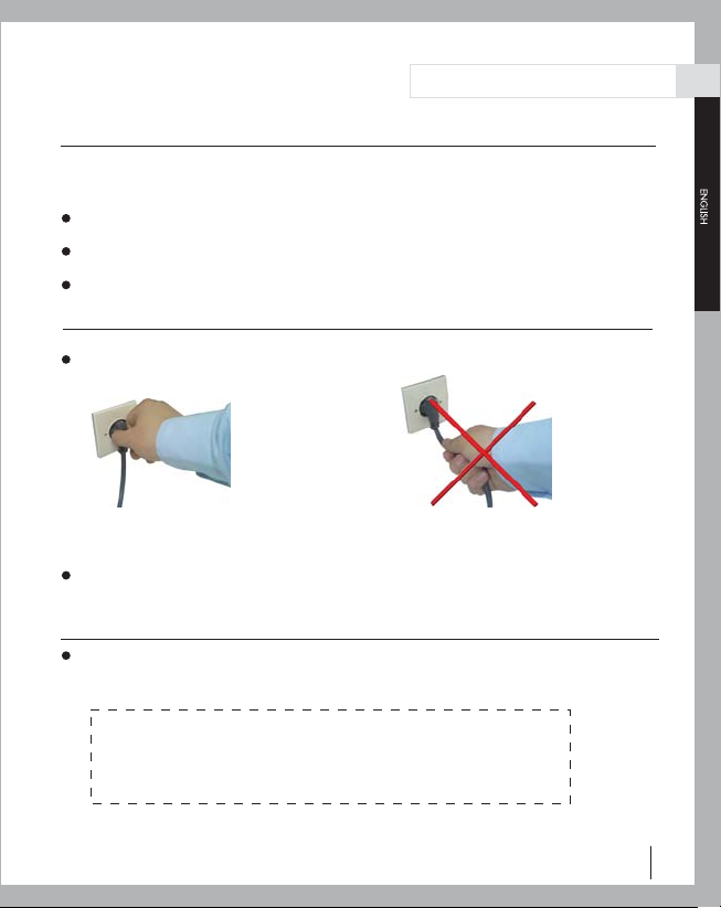
Use your appliance with a properly earthed plug.
The earthed plug must fall outside heating field and hot surface.
The earthed plug must be installed in a level above the heater.
The power cord must not be left on or around the frame of your UFO appliance.
Unplug your appliance when you won’t operate it for a long term or will conduct cleaning or maintenance.
B – Safe distances required for installation on the wall, high temperature and fire protection
Attention! The appliance must only be operated in a horizontal position with max ±'b1 5º'bc slope. In case
of operations in angles larger than 5º'bc in horizontal position or of vertical operations, the heating loop wire
may fall into disuse shortly.
Never install your appliance on a combustible surface (carton etc.)
The distance of your appliance from the ground is to be min 1,8 m.
The distance of your appliance from the ceiling is to be min 0.7 m.
The distance of your appliance from the corners to be installed is to be min 0.4 m and from the combustibles
like curtains must be min 1m.
The distance of your appliance from the living beings is to be min 1m.
The distance of heating area of your appliance from the materials such as wood, carton, cloth etc., must be
min 1 m.
Do not cover your appliance and do not hang any clothing over the heater or do not place any clothing on or
near the appliance.
Do not stick anything into the protective grid.
Do not make use of your heater to light up cigarette or similar materials.
Supervision is needed when this product is used anywhere near children. The appliance is not intended for use
by children or other persons without assistance or supervision if their physical, sensory or mental capabilities
prevent them from using it safely.
2. SAFETY
A – Electrical Connection Safety
The heater glass has to be exchanged at a damage.
If the cable of the heater should be damaged, this may be replaced only by the authorized service.
It has to be notified that the mounting in the bath must be so that the persons in the bath can not reach the controls.
It has to be notified that the product has to be installed at a dry location and may not be wet.

2.2 Safety Instructions (C + D + E)
UFO User Manual & Certificate Of Warranty 3
Distinguished Customer;
Please read safety instructions carefully for the security of you, your
family and your belongings before operating your appliance.
C – The distance from bath tub, washbasin or other sanitary installations
You may operate your heater in the bathroom and outdoors considering the items below:
The distance of your appliance from bath tub, washbasin or other sanitary installations is to
be min 0.6 m. The distance of 1 m is recommended for more safety.
The distance of the earthed plug from bath tub, washbasin or other sanitary installations must
be min 0.6 m.
1 m distance is recommended for more safety.
D –Cleaning and Maintenance Instructions (see page 17)
Unplug your heater first. Never pull your power cable to unplug your heater.
Unplug power cable Never pull your power cable to
unplug your heater
Take out the front grid to clean the reflector (reflecting mirror) and the filament and apply the
instructions on page 17.
E – Repair and Service (page 18)
Attention! Only technical services and persons authorized by SUN may serve, repair and replace
the parts of this heater.

3.1 Installation Instructions
Installation on the wall: Attention! The appliance must be installed on the solid surfaces like concrete
and metal.
Never install on flammable surfaces!
See pages 4-7 to come up with the most appropriate installation method for your UFO.
UFO User Manual & Certificate Of Warranty
4
3. INSTALLATION
1- Drill four 8 mm diameter holes on the wall to the place where the unit will be placed with the
distances shown in (Figure-1)
2- Insert the 8 mm diameter wall plugs,supplied with the unit ,into the holes.
3- Mount two of the L shaped legs on the wall using the 5x40 screws supplied with the unit.
4- Mount the other L legs on the unit using the six M5 screws and the small wrench as shown in
(Figure-2) (corresponding nuts are already built in on the body of the unit)
5- Mount and fix the L shape legs on the wall and on the unit respectively,using the M8x13 bolts and
nuts and the washers as shown in (Figure-3) and tighten by using the wrench supplied.
6- Depending on the area to be heated the angle of the unit can be adjusted between 0-45 degrees
by the help of M8 bakelite head bolt and nut fixture.
7- Before operating the unit joints should be checked once again.
Figure-4
Figure-3
Figure-2
Figure-1

3.2 Installation Instructions Position + Distance
UFO User Manual & Certificate Of Warranty 5
Installation Positions: Attention! Fixing only at ±'5º horizontally is of great importance for
permanent operation.
WRONG RIGHT
Safety Distances: Minimum distances required for safety
Minimum distances from wall corners Minimum distances from coverage
area and other objects
WRONG
5º or more slope
Min. 40 cm
Min. 180 cm Min. 70 cm
Floor

3.3 Installation Instructions with Right and Wrong Positions
6
WRONG
WRONG
RIGHT
RIGHT
WRONG RIGHT
DIRECT YOUR HEATER TOWARDS THE MOST APPROPRIATE ANGLE
Do not let the light out through window, glasses etc. as the heater primarily heats the locations onto
which its light falls.
UFO User Manual & Certificate Of Warranty

4. Application Fields
UFO User Manual & Certificate Of Warranty 7
Application fields of UFO Line and UFO Star models.
Home Applications
Office Applications
Sitting room
Nursery room for children
Guest room
Corridor
Bathroom
Nursery room for babies
Study room
Summer house
Hobby house
Swimming pool
Office
Meeting room
Entrance
Workshop
Shop
Internet cafe
Shopping centre
Showrooms
Swimming pool
Classroom
Conservatories
Places of worship
Factories and production bands
Warehouse and loading zones
Exhibition
Hotel, nursery rooms
Passages
Warming spots in the airports
Warming spots in the train stations

UFO User Manual & Certificate Of Warranty
8
5. Technical Information – Heating Area / Size
Product Name / Model / Volt / Watt / Heating Area / Size H
P
L
H: Height P: Profundity L: Length
MODEL
Heating Area
V(~)
(±10) Watt
Size
H (cm) P (cm) L (cm)
UFO - L / 12
UFO - L / 15
UFO - L / 12
UFO - L / 18
UFO - L / 23
UFO - L / 30
Weight
110-120
110-120
220-230
220-230
220-230
220-230
1200 - 1400
1500 - 1700
1200 - 1300
1800 - 2000
2300 - 2500
2900 - 3200
19
19
19
19
19
19
10
10
10
10
10
10
74
74
74
86
86
108
3,7
3,7
3,7
4
4
5
8
10
8
12
16
20
Outdoors
(m2)
Volt Power
(kg)
Indoors
(m2)
12
15
12
18
23
30
UFO LINE
Hertz
(Hz)
50 - 60
50 - 60
50 - 60
50 - 60
50 - 60
50 - 60
UFO - S / 12
UFO - S / 15
UFO - S / 18
UFO - S / 23
UFO - S / 30
110-120
110-120
220-230
220-230
220-230
1200 - 1400
1500 - 1700
1800 - 2000
2300 - 2500
2900 - 3200
19
19
19
19
19
10
10
10
10
10
74
74
86
86
108
3,7
3,7
4
4
5
8
10
12
16
20
12
15
18
23
30
UFO STAR
50 - 60
50 - 60
50 - 60
50 - 60
50 - 60
UFO - UK / L
UFO - UK / L2
220-230
110-120
Min. 1800
Max. 3200 19
19
10
10
112
78
5,2
4
UFO LINE REMOTE CONTROL
50 - 60
50 - 60 Min. 500
Max. 1700
Min. 12
Max. 20
Max. 10
Min. 18
Max. 30
Min. 5
Max. 15
MODEL
Heating Area
V(~)
(±10) Watt
Size
H (cm) P (cm) L (cm)
Weight
Outdoors
(m2)
Volt Power
(kg)
Indoors
(m2)
Hertz
(Hz)
MODEL
Heating Area
V(~)
(±10) Watt
Size
H (cm) P (cm) L (cm)
Weight
Outdoors
(m2)
Volt Power
(kg)
Indoors
(m2)
Hertz
(Hz)

6. OPERATING INSTRUCTIONS
UFO User Manual & Certificate Of Warranty 9
The thermostat adjustment is conducted in accordance with required room temperature.
Switch the thermostat on the highest mode to heat the cold rooms.
The heater operates constantly when the thermostat is in the highest mode.
When desired room temperature has been attained, the heater may be operated with certain
intervals adjusting the thermostat (21-24 C).
You may reduce the energy costs to the minimum level in certain room temperatures through
appropriate thermostat adjustment.
Switching off during the maintenance or long term disuse
When the appliance is not operated for long a term, cleaning or maintenance is conducted or
when the location of the heater is changed, the electricity connection is turned off unplugging
the power cord and adjusting the thermostat in “0” mode.
Heat Control by Thermostat UFO
6.1 UFO Line / UFO Star

6.2 UFO Line UK
UFO User Manual & Certificate Of Warranty
10
The functions of your heater may be controlled via the buttons on your remote control and LCD screen.
You may also control some of the functions of your heater through the buttons on the front side of
the heater.
6.2.1 Definitions of the Buttons on the Remote Control
Warning!
Insert the batteries of your
remote control
9
1
2
5
8
7
6
4
3
1. On / Off
Switches on or off the heater or stands it by.
+ -
2. / (Program Up / Down)
Adjusts program settings..
3. Clock
Sets the time.
4. Timer On
Switches on the heater in stand by mode.
5. Timer Off
Switches off the heater in preset time and starts stand by mode.
6. Sleep
Switches off the heater in preset time
7. Everyday
Makes the heater operate in preset parameters everyday.
8. Cancel
Cancels all settings.
9. LCD (Liquid Cristal Display)
Displays the settings of the remote control and related indicators.
Remote Control

6.2.2 Definition and Functions of the Indicators on the Remote Control
UFO User Manual & Certificate Of Warranty 11
Symbol
Power mode indicator
Time settings indicator
On time indicator
Off time indicator
Indicates remaining time to switch off the heater
Indicates that “'everyday” function is on
Logo
Description

6.2.3 Operation of the Remote Control
UFO User Manual & Certificate Of Warranty
12
Inserting Batteries
Insert 2 AAA/ Alkaline type batteries into your Remote Control.
The screen of the remote control starts functioning after inserting the batteries. UFO logo and
flashing clock indicator starts appearing on the screen.
Power mode indicator (mode1) starts functioning after pressing On / Off button.
1- Flip the backside of your remote control and pull out battery
cover. Insert the batteries in accordance with the instructions and
polarity of the batteries.
2- Change the batteries in the same way depicted above.
NOTICE:
1- Replace the old batteries with the same type batteries.
Otherwise, your heater may not function well.
2- Pull out the batteries in case of long terms of disuse
to prevent leakage which may impair your remote
control.

6.2.3 Operation of the Remote Control
UFO User Manual & Certificate Of Warranty 13
Power Mode Adjustment
Press / buttons to adjust the power mode of your heater. Time settings are to be conducted
for the rest of the functions to operate.
Time Settings
Adjusting the time
Press Clock button.
Press / buttons to set hour and minutes. Press Clock button to save your settings. Press Cancel
button to cancel time settings.
NOT: Repeated presses on the buttons will gear the speed of buttons and intervals with the presses
will slow down the process.
On / Off Time
Warning! The time is to be set precisely and the heater is to be operating before using On / Off time
function.
On Time Settings
Press Timer On button. Press / buttons to set hour and minutes. Press Timer On button to
save your settings.

6.2.3 Operation of the Remote Control
UFO User Manual & Certificate Of Warranty
14
Off Time Settings
Press Timer Off button.
Press / buttons to set hour and minutes.
Press Timer Off button to save your settings.
Sleep Timer Settings
Warning! The time is to be set precisely and the heater is to be operating before using Sleep Timer
function.
Press Sleep button.
Press / buttons to set sleep time from 1 to 12 hours.
Press Sleep button to save your settings.
Remaining time will appear on the screen.
Note:
Press Cancel button to cancel all time settings. The settings will recede unless you press (Clock,
Timer On, Sleep ve Timer Off ) necessary button to save your time settings in 20 seconds.
Press Cancel button to cancel all kinds of time settings.
Repeated presses on the buttons will gear the speed of buttons and intervals with the presses will
slow down the process.
Press Cancel button with the intervals of 3 seconds to cancel all settings of your remote control.
Set your Sleep timer again in case of turning off and on the heater.
Once you set your On/Off time, such functions will operate in daily set times.
The heater is to be in stand-by mode to operate On timer.
Clock and UFO logo keeps functioning in stand by mode.

6.2.4 Manual Operation
UFO User Manual & Certificate Of Warranty 15
Control through the main module on the heater:
HO indicator appears on the screen when the heater is switched on and it is in stand by mode.
The 1st digit on the screen illustrates Hsymbol while 2nd digit illustrates power level mode from
1 to 5.
The button number 1 on the heater functions as ON / OFF. The heater starts operating at the power
level mode at which it has been switched off.
Press the button number 2 on the heater to adjust power mode.
Tilt indicator starts functioning and “2 ” 3 indicator appears on the screen warning through a buzzer
voice when the heater operates in a slope larger than 5°. The heater starts operating in stand by
mode (H0) when it has been adjusted in the right position.
H0 appears on the screen when pressed ON / OFF button and the power level mode (H1, H2, H3,
H4 and H5) is adjusted through the buttons on the remote control.
Press ON / OFF button on the remote control or the heater itself to switch off the heater.
The heater starts functioning in stand by mode after electricity cut.
LED keeps flashing in case of a program set by remote control.
Buzzer signal is given following each command.
LED
Power level indicator
H
ON/OFF Power mode button

7. Difference among UFO Models and Specifications
UFO User Manual & Certificate Of Warranty
16
* In case of appropriate operations
Body Color
Body material
Warranty
* Filament life time / Hours
Plastic Cover
Power cord length
Remote control
Reflector
Reflector side part
Grid Wire
Voltage
Frequency
Naturel
Champagne
Aluminium
2 years
3 years
4 years
12.000
9.000
6.000
Holey
Flat
2,75 m
IR- control
Aluminium
Aluminium
16x16x1.2 mm
220 ± 10 V (AC)
50 Hertz
Line Star
UFO MODELS
UFO
Line UK
This manual suits for next models
11
Table of contents
Languages:
Other UFO Heater manuals
Popular Heater manuals by other brands

Atlantic
Atlantic DIVALI manual

Kambrook
Kambrook CARBON KCF200 Instruction booklet

Jaga
Jaga Iguana Arco Mounting instructions

Systema
Systema INFRA...ROSSO SCR 1 25M instruction manual

CHAFFOTEAUX
CHAFFOTEAUX EXPERT CONTROL Assembly and operation instructions

Vitrulan
Vitrulan V4heat Anti-Mold Kit Operating and assembly instructions