UFO NSDCN65S User manual

NSDCN65S OPERATION MANUAL
NSDCN65S/SP Technical Data
NAIL DIMENSIONS:
Length
12-1/4"
15° Round Head Coil nails
Width
5"
Length: 1-3/4” – 2.5”
Height
12-1/2"
Shank diameter: .090”– .113”
Weight
6.4lbs
Head: .224” – .276”
Operating Pressure
70-120psi
PACKING LIST:
QTY
Instruction Manual Contents:
◎Important Safety Rules
NSDCN7515 COIL NAILER
1
◎Operating Instructions
S5 HEX KEY
1
S4 HEX KEY
1
◎Maintenance
◎Troubleshooting
S3 HEX KEY
1
◎Parts List
AIR TOOL OIL
1
◎Composite Fencing Installation
SAFETY GLASSES
1
BUMP OR SEQUENTIAL
FIRE TRIGGER
1

3
2
Description: Ballistic NailScrew® Driver: Model NO. NSDCN65S/SP is a heavy duty, coil fed, pneumatic
nailer, using compressed air as power source. It is designed to drive 15° plastic sheet coil or 15° wire coil
with full round head Ballistic NailScrews® or nails 1-1/4” to 2.5” in length and 0.086˝ to 0.113˝ in diameter.
The NSDCN65S/SP was specialty designed for UFO’s Ballistic NailScrew® program with the ease of
installation and durability in mind. The power to easily drive color matched Ballistic NailScrews® into
wood or composites into light gauge (12 to 20ga) steel frame and stop the drive when it is flush. This is
possible, but must be done a little differently that what you may be used to when you are attaching wood to
wood, so please follow these step by step rules when installing into steel.
Consistent air pressure is the key to success. The closer to the compressor the better, but when
long runs of 3/8”air hose are necessary, the use of a surge tank will be necessary.
Keep the pressure high--110 to120psi; the high velocity this creates is our friend. Please understand
this is where we are different than fastening to wood. Always be sure to test fire into the actual
material scraps, adjusting the depth of drive on the tool (See C Fig .19) to compensate for the excess
pressure. Lower the pressure as a last resort and as little as necessary to get the job done.
The NSDCN65S/SP should be sequentially fired into steel. First, place the nose of the tool where
you want the fastener to be; this will depress the safety. Second, use the trigger to fire the tool in
this sequence each and every time. The tool must be placed squarely and very firmly; try not to let
the tool bounce off the work surface. This will give a more consistent drive and finished look.
When you have a Ballistic NailScrew® that is too high or low, use a T15 Torx bit in a screw driver
or impact driver to adjust the NailScrew®. Go very slowly to the desired depth. High rpm will strip
out the NailScrew®. Go slow and you will be amazed at the results.
This is very important! Please make sure the frames are set very firm--not springy or bouncy. If the
frame moves much, it will cause the NailScrews®to be set very inconsistently.
NSDCN65S/SP
has very low noise level, making it ideal for installing Ballistic NailScrews® for Composite fencing to wood
or steel, construction of pallets and crate assembly, composite or wood deck construction, roof decks, sub-
floor, sidewall sheathing, anywhere screws are being used and you want to save time installing and still do
a quality job etc. (see http://911-nails.com)
ONLY USE PARTS AND ACCESSORIES RECOMMENDED BY THE MANUFACTURER.
Parts & Service Contact: http://elder-hayesinc.com or call 1-800-769-0775

3
IMPORTANT! Upon receipt of your NailScrew® Driver, Read and
follow all safety rules and operating instructions.
Important Safety Rules
1. KEEP CHILDREN AWAY. All children should be kept away from the work area.
Do not allow them to handle the tool. Fig 1.
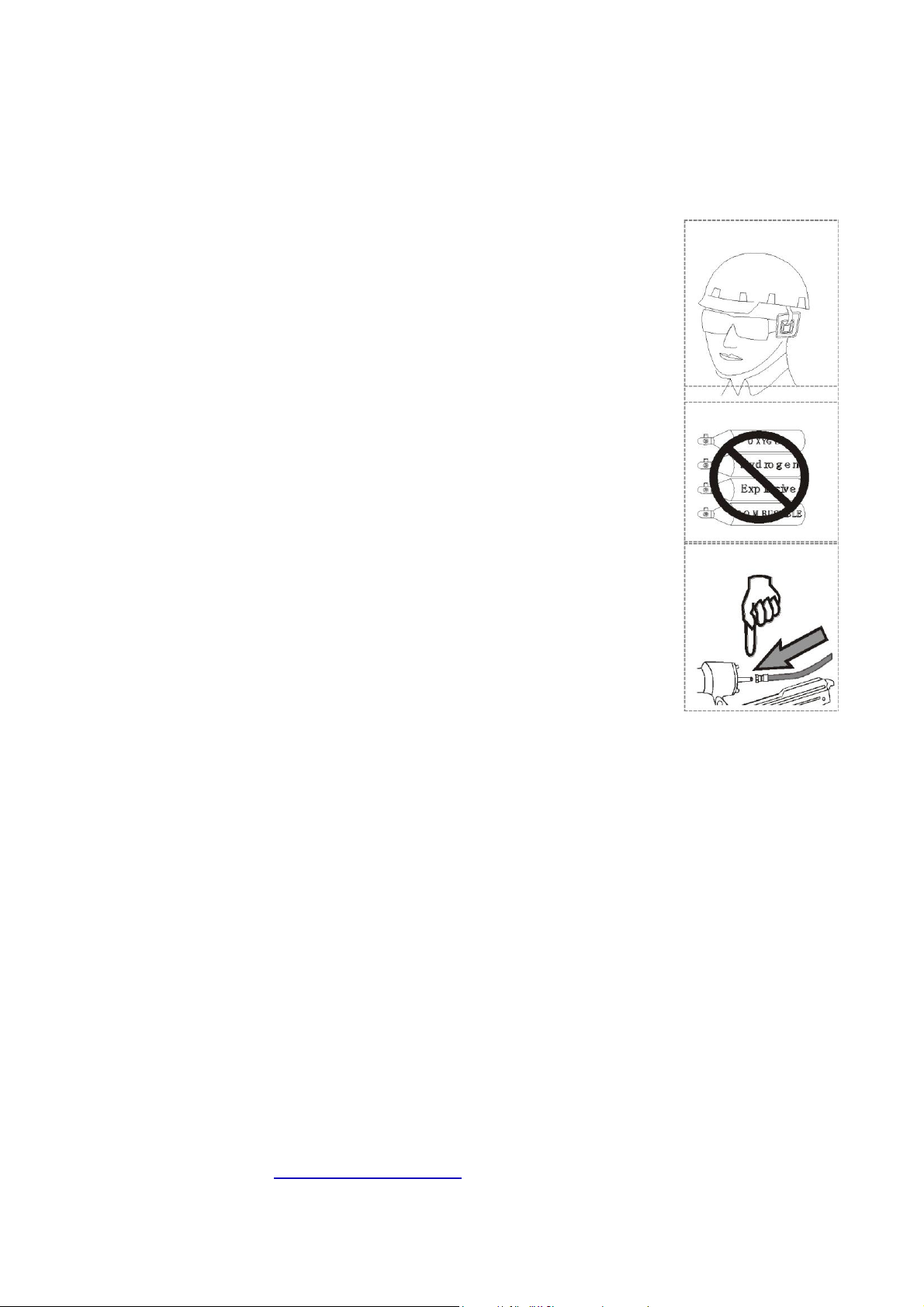
2. USE SAFETY GLASSES AND EAR PROTECTION. Air tool operators and
others in the work area should always wear safety glasses to prevent injury from
fasteners and flying debris during use and when loading and unloading this tool.
Wear ear protection to safeguard against hearing loss. (See fig 1.)
3. NEVER USE OXYGEN, COMBUSTIBLE FUELS OR ANY OTHER BOTTLED
GAS as a power source as it will cause explosion and serious personal injury.
(See fig 2.)
Fig 2.
4. DO NOT CONNECT TOOL TO COMPRESSED AIR WITH
PRESSURE EXCEEDING 120PSI.
5. DO NOT USE AN EXCESSIVELY LONG AIR HOSE in the working area as it
will create an operator tripping hazard. Secure all connections tightly.
6.
CARRY TOOL ONLY BY THE HANDLE
and keep finger off the trigger pull.
This
Fig 3
will allow the safety yoke mechanism to prevent the unintentional firing of
fasteners.
7. KEEP THE TOOL POINTED AWAY FROM YOURSELF AND OTHERS at all
times. Keep hands and all body parts away from the nose area and rear area of
the tool to guard against possible injury.
8. DISCONNECT TOOL FROM AIR SUPPLY BEFORE LOADING FASTENERS to prevent accidental
fastener firing. (See fig3.)
9. DO NOT DEPRESS TRIGGER OR SAFETY YOKE MECHANISM DURING FASTENER LOADING
to prevent the unintentional firing of a fastener that can cause personal injury.
10. DISCONNECT TOOL FROM AIR SUPPLY HOSE and disconnect from air compressor before
performing maintenance, altering accessories, or while not in operation.
11. DO NOT OPERATE ON SCAFFOLDINGS OR LADDERS, and do not work in airtight containers or vehicles.
12. DO NOT DRIVE FASTENERS CLOSE TO THE EDGE OF THE WORK PIECE. The work piece could split,
causing the fastener to fly free or ricochet, causing personal injury.
13. DO NOT DRIVE FASTENERS ON TOP OF OTHER FASTENERS or the fasteners can ricochet
causing personal injury.
14. NEVER USE A TOOL THAT IS LEAKING AIR, HAS MISSING OR DAMAGED PARTS, OR IS IN NEED
OF REPAIR. Make sure that all screws are securely tightened.
15. INSPECT DAILY FOR FREE MOVEMENT of trigger, safety mechanism and spring to insure safe and
proper operation of the tool.
16. ONLY USE PARTS AND ACCESSORIES RECOMMENDED BY THE MANUFACTURER.
Parts & Service Contact: http://elder-hayesinc.com or call 1-800-769-0775

4
POWER SOURCE
This tool is designed to operate on clean, dry, compressed air at regulated pressures between 70 and
120 PSI (4.9 and 8.3 bar) (Pounds per Square Inch). The preferred system would include a filter.
CAUTION: All line components (hoses, connectors, filters, regulators, etc.) must meet 150% of the
maximum system pressure. Please try to use a hose of ID 3/8” connecting nailer with compressor.
Disconnect tool from air supply before performing maintenance, clearing a jammed fastener, leaving
work area, moving tool to another location, or handing the tool to another person.
PREPARING THE TOOL BEFORE DRIVING
1. After reading and understanding this entire manual, connect tool to air
supply. CAUTION: Keep tool pointed away from you and others at all times.
Always connect tool to air supply before loading fasteners. Do not load fasteners with trigger or safety
depressed. Always wear Z87 approved safety glasses, and hearing protection when preparing or
operating the tool. Never use a tool that leaks air or needs repair.
2. Depress Handle and open the Latch. Rotate the Upper Nail Housing to the side of the Body. (FIG
3. The Adjuster Plate can be moved up and down by twisting the spindle and pulling up to decrease or
pushing down to increase to the length of nail (FIG. 15), the Adjuster Plate should be adjusted
correctly to the position indicated inside Lower Nail Housing. (FIG.16)
(FIG.15) (FIG.16)
4. Place a coil of nails over the Lower Nail Housing. Uncoil enough nails to reach the Feed Paw and place
the second nail between the teeth on the Feed Paw.

5
5. Close the Nail Housing door and depress the Latch
6. Adjust directional EXHAUST deflector so that the exhaust air blast will be directed away from the
operator. Grasp the deflector and rotate it to the desired position for the current application.
RUBBER NO-MAR TIP:
ADJUSTING THE DRIVE DEPTH:
Driving depth will be adjusted by rolling the red wheel (FIG. 19) Test fire a fastener and check depth. If the
nail is driven too high, rotate the rolling wheel clockwise (right) if the nail is too deep rotate the rolling wheel
counter clockwise (left). Repeat this step until you reach desired depth. The red tear drop on the trigger
(FIG. 19) will allow you to change from sequential to bump fire. Reach behind the trigger and push up (FIG.
20) this will allow raise the red tear drop then you can rotate the tear drop 180º so it will drop back into
trigger flush as shown in (FIG. 21).
(FIG. 19) (FIG. 20) (FIG. 21)
CLEARING A JAMMED FASTENER:
1. CAUTION: Disconnect tool from air supply.
2. Open latch, rotate lower housing and remove the nails of the lower housing.
3. Use a slender, soft steel rod to drive the drive blade to its upper most position.
Use needle nose pliers to remove the jammed fastener.
4. Follow instructions in PREPARING THE TOOL BEFORE DRIVING to reload fasteners.

6
Service advice:
1. Use clean, dry and regulated compressed air, 8 cfm at 5.0-7.5 bar (70-120psi) and 100-120psi at the tool.
2. Never exceed the maximum and minimum pressures. Too low or too high pressure will cause noise,
increased wear or misfiring.
3. When connecting the air supply, always keep hands and body from the discharge area of the tool.
4. A filter-regulator-lubrication is required and should be located as close to the tool as possible (see fig.4).
5. Keep the air filter clean. A dirty filter will reduce the air pressure to the tool, causing a reduction in power and
efficiency.
6. For better performance, install a quick connector in your tool and quick coupler on the hose, if possible.
7. Make sure that all connections in the air supply system are sealed to prevent air loss.
Fig 4.
Tool
WARNING: Never operate tool unless safety nose is in contact with work-piece. Do not
operate tool without fasteners or damage to the tool may result. Never fire fasteners into air!
Fasteners may injure the operator or others, and damage to the tool may result.
※Maintenance
WARNING:Disconnect the tool from the air compressor when not in use and
beforeadjusting, clearing jams, servicing, or relocating.
Regular lubrication. If your tool does not have an in-liner automatic oilier, place 2 to 6 drops
of pneumatic tool oil into the air inlet before each work day or after 2 hours of continuous
use, depending upon the characteristics of your work or type of fasteners.
As needed, check and change all worn or damaged o-rings, seals, etc. Tighten all
screws and caps to prevent personal injury.
Inspect trigger and safety mechanisms to assure the safety system is complete and
functional; guard against loose and missing parts, build-up, and binding or sticking
parts.
Keep magazine and the nose of the tool clean and free of dirt, lint or abrasive particles.
ONLY USE PARTS AND ACCESSORIES RECOMMENDED BY THE MANUFACTURER.
Parts & Service Contact: http://elder-hayesinc.com or call 1-800-769-0775

7
※Troubleshooting
Following are common operating problems and solutions.
Please read carefully for suggested solutions.
WARNING:If any of the following symptoms occur during tool operation, stop using the
tool immediately or serious personal injury could result! Only a qualified person or an authorized
service center can perform repairs or replacement of tool parts. Disconnect tool from air supply
before attempting any repair or adjustment. When replacing O-rings or cylinder, lubricate with air
tool oil before assembly.
SYMPTOM
PROBLEM
SOLUTIONS
Air leak near top of tool or
1.
O-ring in trigger valve is damaged.
1.
Check and replace O-ring.
in trigger area
2.
Trigger valve head is damaged.
2.
Check and replace.
3.
Trigger valve stem, seal or O-ring
3.
Check and replace trigger valve
is damaged.
stem, seal or O-ring.
Air leak near bottom of
1.
Loose screws.
1.
Tighten screws.
tool.
2.
Worn or damaged O-rings or
2.
Check and replace O-rings or
bumper.
bumper.
Air
leak
between
body
1.
Loose screws.
1.
Tighten screw.
and cylinder cap.
2. Worn or damaged O-rings or seals.
2.
Check and replace O-rings or
bumper.
Fastener
being driven
to
1.
Need to adjust depth control.
1. Adjust depth control (Fig. 19)
too deep.
2. Air pressure is too high.
2. Adjust the air pressure.
3. Worn bumper.
3.
Replace bumper.
Tool does not operate well:
1.
Inadequate air supply.
1.
Verify adequate air supply.
cannot drive fastener
or
2.
Inadequate lubrication.
2. Place 2 or 6 drops of oil into air inlet.
operates sluggishly.
3. Worn or damaged O-rings or seals.
3.
Check and replace O-rings or seal.
4.
Exhaust port in cylinder head is
4.
Replace damaged internal parts.
blocked.
Tool skips fasteners.
1.
Incorrect dish adjustment.
1.
See Instruction #3 (Fig. 15)
2.
Dirt in front plate.
2.
Clean drive channel on front plate.
3. Dirt or damage prevents fasteners
3.
Magazine needs to be cleaned.
from moving freely in magazine.
4. Worn or dry O-ring on feed piston
4.
O-ring needs to be replaced
or lack of lubrication.
and lubricated.
5.
Cylinder covers seal leaking.
5.
Replace Sealing washer.
Tool jams.
1.
Incorrect dish adjustment.
1.
See Instruction #3 (Fig. 15)
2.
Damaged or worn driver guide.
2.
Check and replace the driver.
3.
Magazine or nose screw loose.
3.
Tighten the magazine.
4. Worn or dry O-ring on feed piston
4.
O-ring needs to be replaced
or lack of lubrication.
and lubricated

8
NSDCN65S
Item
Part
Number
Description
Item
Part
Number
Description
101
820641
SHCS BOLT
408
920548
FEED BUMPER
102
820408
WASHER
409
920549
FEED PISTON CAP
103
820320
DEFLECTOR
410
920585
C - RING
104
810643
MUFFLER
411
810331
FEEDER PAW
105
820041
RUBBER WASHER
412
810333
FEEDER SPRING
106
820163
CAP
414
920553
RETAINER
107
920164
SHCS BOLT
415
810341
FIRST STOPPER FINGER
108
820410
WASHER
416
920627
RETAINER
109
810868
COMPRESSION SPRING
417
810342
SPRING
110
820147
HEAD VALVE
418
820129
FIXED PIN
111
830314
O - RING
419
820034
FIXED PIN
112
830248
O - RING
420
820106
DOOR SHAFT PIN
113
810901
SEAL
421
820101
DOOR
114
820309
SEAL
422
920561
LATCH SPRING
115
820563
COLLAR
423
920562
DOOR LATCH
116
810636
GASKET
424
820841
ROLL PIN
117
830308
O - RING
425
820023
NAIL GUIDE
118
810012
DRIVER UNIT
426
810839
SPRING
119
810510
CYLINDER
427
820028
FIXED PIN
120
830347
O - RING
428
820648
SHCS BOLT
121
810521
CYLINDER SPACER
429
820667
SHCS BOLT
122
830359
O - RING
430
810941
SAFETY COVER
123
810529
CYLINDER RING
431
920573
NUT
124
920822
BUMPER
432
810826
SAFETY GUIDE
125
810431
CYLINDER PRESS RING
433
820833
ROLL PIN
126
820202
FLANGE
434
810806
SAFETY SPRING
201
IN KIT
O - RING
435
810717
UPPER SAFETY
202
IN KIT
O - RING
436
820534
DEPTH ADJUSTMENT
203
IN KIT
UPPER TRIGGER VALVE
437
820374
SAFETY COVER
204
IN KIT
VALVE PLUNGER
438
820536
ADJUST ROD
205
IN KIT
O - RING
439
830271
O - RING
206
IN KIT
O - RING
440
810712
LOWER SAFETY
207
IN KIT
SPRING
441
920211
E - RING
208
IN KIT
PLUNGER
442
810835
FLAT NO MAR TIP
209
IN KIT
O - RING
442
810836
POINTED NO MAR TIP
210
IN KIT
LOWER TRIGGER VALVE
443
820007
MAGAZINE COVER
211
IN KIT
ROLL PIN
444
920568
SPRING CLIP
KIT
830402
TRIGGER VALVE ASMBLY
445
920567
PULL SPRING
212
920824
ROLL PIN
446
820013
NAIL TRAY
213
920530
ROLL PIN
447
820001
MAGAZINE
221
810101
TRIGGER
448
810945
SPRING CLIP
222
810882
SPRING
449
820107
FIXED PIN
301
810206
GUN BODY UNIT
450
820047
RETAINER
302
810922
END CAP
451
920581
SHCS BOLT
303
920540
O-RING
452
920572
FLAT WASHER
401
820428
NOSE PIECE
454
920168
LOCK NUT
402
830310
O - RING
455
820429
PLASTIC SHIELD
403
820124
FEEDER PISTON
456
810540
FIXED PIN
404
920584
O - RING
457
920586
FIXED RING
405
830229
O - RING
458
920828
O - RING
407
920547
SPRING
460
830364
O - RING
ONLY USE PARTS AND ACCESSORIES RECOMMENDED BY THE MANUFACTURER.
Parts & Service Contact: http://elder-hayesinc.com or call 1-800-769-0775

9
NSDCN65S
For Parts & Service Contact: http://elder-hayesinc.com or call 1-800-769-0775
This manual suits for next models
1
Table of contents
Other UFO Nail Gun manuals
Popular Nail Gun manuals by other brands

Senco
Senco AirFree 32 operating instructions

Beta
Beta 1947H Operation manual and instructions

Clarke
Clarke Contractor CFN34 Operating & maintenance instructions

REICH
REICH 3555 Technical data spare parts

Central Pneumatic
Central Pneumatic 68021 Set up and operating instructions

Central Pneumatic
Central Pneumatic 68024 Set up and operating instructions