UFO NSDCN65SP User manual

NSDCN65SP OPERATION MANUAL
NSDCN65SP Technical Data NAIL DIMENSIONS:
Length 12-1/4" 15° Round Head Coil nails
Width 5" Length: 1-3/4” – 2.5”
Height 12-1/2" Shank diameter: .090”– .113”
Weight 6.4lbs Head: .224” – .276”
Operating Pressure 70-120psi
PACKING LIST:
QTY
Instruction Manual Contents:
NSDCN7515 COIL NAILER
1
◎Important Safety Rules
S5 HEX KEY
1
◎Operating Instructions
S4 HEX KEY
1
◎Maintenance
S3 HEX KEY
1
◎Troubleshooting
AIR TOOL OIL
1
◎Parts List
SAFETY GLASSES
1
◎Composite Fencing Installation
BUMP OR SEQUENTIAL
FIRE TRIGGER
1

2
Fig 1.
Fig 2.
Description: Ballistic NailScrew Driver: Model NO. NSDCN65SP is a heavy duty, coil fed, pneumatic
nailer, using compressed air as power source. It is designed to drive 15° plastic sheet coil or 15° wire coil
with full round head Ballistic NailScrews® or nails 1-1/4” to 2.5” in length and 0.086˝ to 0.113˝ in diameter.
The NSDCN65SP was specialty designed for UFO’s Ballistic NailScrew® program with the ease of
installation and durability in mind. The power to easily drive color matched Ballistic NailScrews® into wood
or composites into light gauge (12 to 20ga) steel frame and stop the drive when it is flush. This is possible,
but must be done a little differently that what you may be used to when you are attaching wood to wood, so
please follow these step by step rules when installing into steel.
Consistent air pressure is the key to success. The closer to the compressor the better, but when long
runs of 3/8”air hose are necessary, the use of a surge tank will be necessary.
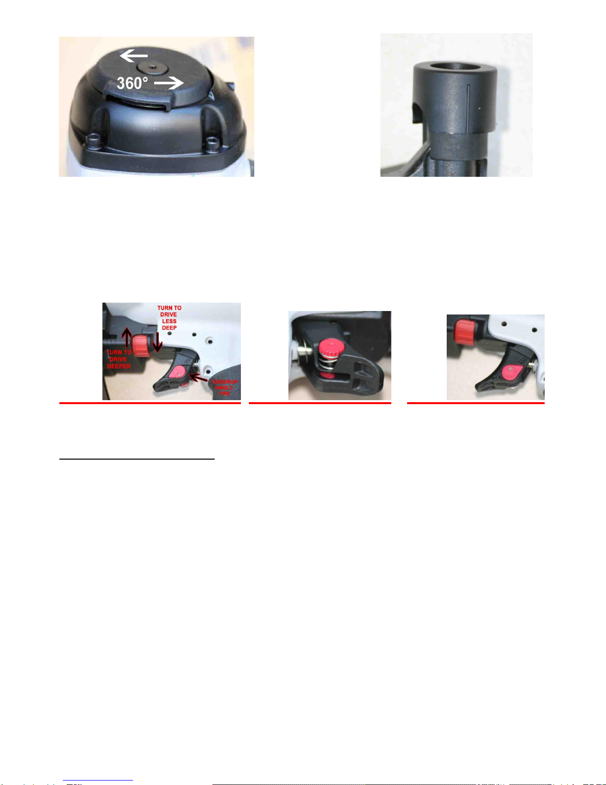
Keep the pressure high--110 to120psi; the high velocity this creates is our friend. Please understand
this is where we are different than fastening to wood. Always be sure to test fire into the actual
material scraps, adjusting the depth of drive on the tool (See C Fig .19) to compensate for the excess
pressure. Lower the pressure as a last resort and as little as necessary to get the job done.
The NSDCN65SP should be sequentially fired into steel. First, place the nose of the tool where you
want the fastener to be; this will depress the safety. Second, use the trigger to fire the tool in this
sequence each and every time. The tool must be placed squarely and very firmly; try not to let the
tool bounce off the work surface. This will give a more consistent drive and finished look.
When you have a Ballistic NailScrew® that is too high or low, use a T15 Torx bit in a screw driver or
impact driver to adjust the NailScrew. Go very slowly to the desired depth. High rpm will strip out the
NailScrew. Go slow and you will be amazed at the results.
This is very important! Please make sure the frames are set very firm--not springy or bouncy. If the
frame moves much, it will cause the NailScrews to be set very inconsistently.
NSDCN65SP has very low noise level, making it ideal for installing Ballistic NailScrews® for Composite
fencing to wood or steel, construction of pallets and crate assembly, composite or wood deck construction,
roof decks, sub-floor, sidewall sheathing, anywhere screws are being used and you want to save time
installing and still do a quality job etc. (see www.911.nails.com)
IMPORTANT! Upon receipt of your NailScrew® Driver, Read and
follow all safety rules and operating instructions.
Important Safety Rules
1. KEEP CHILDREN AWAY. All children should be kept away from the work area.
Do not allow them to handle the tool.
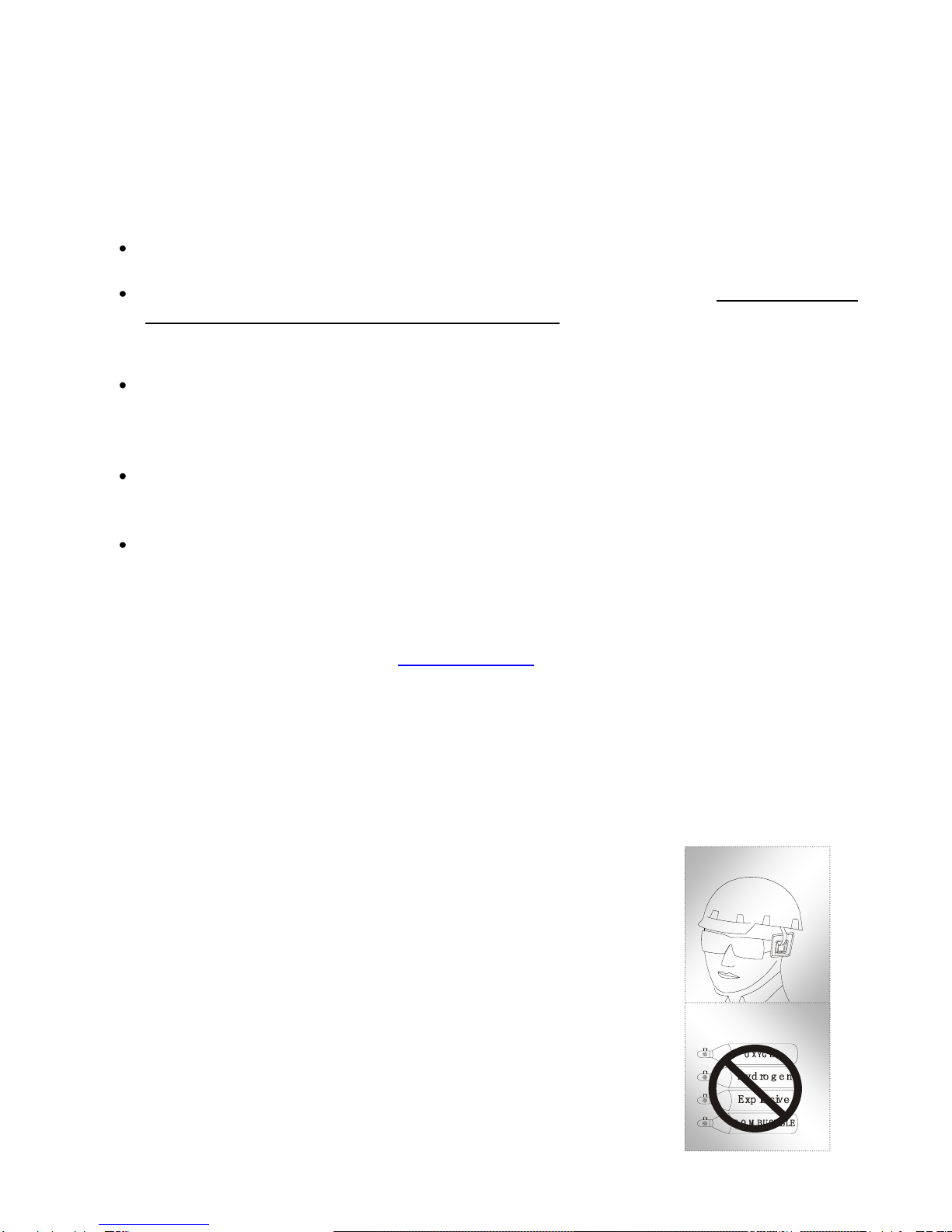
2. USE SAFETY GLASSES AND EAR PROTECTION. Air tool operators and others
in the work area should always wear safety glasses to prevent injury from
fasteners and flying debris during use and when loading and unloading this tool.
Wear ear protection to safeguard against hearing loss. (See Fig 1.)
3. NEVER USE OXYGEN, COMBUSTIBLE FUELS OR ANY OTHER BOTTLED
GAS as a power source as it will cause explosion and serious personal injury.
(See Fig 2.)
4. DO NOT CONNECT TOOL TO COMPRESSED AIR WITH PRESSURE
EXCEEDING 120PSI.
5. DO NOT USE AN EXCESSIVELY LONG AIR HOSE in the working area as it will

3
Fig 3.
create an operator tripping hazard. Secure all connections tightly.
6. CARRY TOOL ONLY BY THE HANDLE and keep finger off the trigger pull. This
will allow the safety yoke mechanism to prevent the unintentional firing of
fasteners.
7. KEEP THE TOOL POINTED AWAY FROM YOURSELF AND OTHERS at all
times. Keep hands and all body parts away from the nose area and rear area of
the tool to guard against possible injury.
8. DISCONNECT TOOL FROM AIR SUPPLY BEFORE LOADING FASTENERS to
prevent accidental fastener firing. (See Fig 3.)
9. DO NOT DEPRESS TRIGGER OR SAFETY YOKE MECHANISM DURING FASTENER LOADING to
prevent the unintentional firing of a fastener that can cause personal injury.
10. DISCONNECT TOOL FROM AIR SUPPLY HOSE and disconnect from air compressor before performing
maintenance, altering accessories, or while not in operation.
11. DO NOT OPERATE ON SCAFFOLDINGS OR LADDERS, and do not work in airtight containers or vehicles.
12. DO NOT DRIVE FASTENERS CLOSE TO THE EDGE OF THE WORK PIECE. The work piece could split,
causing the fastener to fly free or ricochet, causing personal injury.
13. DO NOT DRIVE FASTENERS ON TOP OF OTHER FASTENERS or the fasteners can ricochet causing
personal injury.
14. NEVER USE ATOOL THAT IS LEAKING AIR, HAS MISSING OR DAMAGED PARTS, OR IS IN NEED OF
REPAIR. Make sure that all screws are securely tightened.
15. INSPECT DAILY FOR FREE MOVEMENT of trigger, safety mechanism and spring to insure safe and proper
operation of the tool.
16. ONLY USE PARTS AND ACCESSORIES RECOMMENDED BY THE MANUFACTURER.
Parts & Service Contact: http://elder-hayesinc.com or call 1-800-769-0775
POWER SOURCE
This tool is designed to operate on clean, dry, compressed air at regulated pressures between 70 and 120
PSI (4.9 and 8.3 bar) (Pounds per Square Inch). The preferred system would include a filter.
CAUTION: All line components (hoses, connectors, filters, regulators, etc.) must meet 150% of the
maximum system pressure. Please try to use a hose of ID 3/8” connecting nailer with compressor.
Disconnect tool from air supply before performing maintenance, clearing a jammed fastener, leaving work
area, moving tool to another location, or handing the tool to another person.
PREPARING THE TOOL BEFORE DRIVING
1. After reading and understanding this entire manual, connect tool to air supply.
CAUTION: Keep tool pointed away from you and others at all times.
Always connect tool to air supply before loading fasteners. Do not load fasteners with trigger or safety
depressed. Always wear Z87 approved safety glasses, and hearing protection when preparing or
operating the tool. Never use a tool that leaks air or needs repair.
2. Depress Handle and open the Latch. Rotate the Upper Nail Housing to the side of the Body. (FIG

4
3. The Adjuster Plate can be moved up and down by twisting the spindle and pulling up to decrease or
pushing down to increase to the length of nail (FIG. 15) , the Adjuster Plate should be adjusted correctly
to the position indicated inside Lower Nail Housing. (FIG. 16)
(FIG. 15) (FIG. 16)
4. Place a coil of nails over the Lower Nail Housing. Uncoil enough nails to reach the Feed Paw and place
the second nail between the teeth on the Feed Paw.
5. Close the Nail Housing door and depress the Latch.
6. Adjust directional EXHAUST deflector so that the exhaust air blast will be directed away from the
operator. Grasp the deflector and rotate it to the desired position for the current application.

5
RUBBER NO-MAR TIP:
ADJUSTING THE DRIVE DEPTH:
Driving depth will be adjusted by rolling the red wheel (FIG. 19) Test fire a fastener and check depth. If the
nail is driven too high, rotate the rolling wheel clockwise (right) if the nail is too deep rotate the rolling wheel
counter clockwise (left). Repeat this step until you reach desired depth. The red tear drop on the trigger
(FIG. 19)will allow you to change from sequential to bump fire. Reach behind the trigger and push up (FIG.
20) this will allow raise the red tear drop then you can rotate the tear drop 180º so it will drop back into
trigger flush as shown in (FIG. 21).
(FIG. 19)(FIG. 20) (FIG. 21)
CLEARING A JAMMED FASTENER:
1. CAUTION: Disconnect tool from air supply.
2. Open latch, rotate lower housing and remove the nails of the lower housing.
3. Use a slender, soft steel rod to drive the drive blade to its upper most position.
Use needle nose pliers to remove the jammed fastener.
4. Follow instructions in PREPARING THE TOOL BEFORE DRIVING to reload fasteners.
Service advice:
1. Use clean, dry and regulated compressed air, 8 cfm at 5.0-7.5 bar (70-120psi) and 100-120psi at the tool.
2. Never exceed the maximum and minimum pressures. Too low or too high pressure will cause noise, increased
wear or misfiring.
3. When connecting the air supply, always keep hands and body from the discharge area of the tool.
4. A filter-regulator-lubrication is required and should be located as close to the tool as possible (see Fig.4).
5. Keep the air filter clean. A dirty filter will reduce the air pressure to the tool, causing a reduction in power and
efficiency.
6. For better performance, install a quick connector in your tool and quick coupler on the hose, if possible.

6
7. Make sure that all connections in the air supply system are sealed to prevent air loss.
WARNING: Never operate tool unless safety nose is in contact with work-piece. Do not
operate tool without fasteners or damage to the tool may result. Never fire fasteners into air!
Fasteners may injure the operator or others, and damage to the tool may result.
※Maintenance
WARNING: Disconnect the tool from the air compressor when not in use and before
adjusting, clearing jams, servicing, or relocating.
Regular lubrication. If your tool does not have an in-liner automatic oilier, place 2 to 6 drops
of pneumatic tool oil into the air inlet before each work day or after 2 hours of continuous use,
depending upon the characteristics of your work or type of fasteners.
As needed, check and change all worn or damaged o-rings, seals, etc. Tighten all screws
and caps to prevent personal injury.
Inspect trigger and safety mechanisms to assure the safety system is complete and
functional; guard against loose and missing parts, build-up, and binding or sticking parts.
Keep magazine and the nose of the tool clean and free of dirt, lint or abrasive particles.
ONLY USE PARTS AND ACCESSORIES RECOMMENDED BY THE MANUFACTURER.
Parts & Service Contact: http://elder-hayesinc.com or call 1-800-769-0775
Fig 4.
To ol

7
※Troubleshooting
Following are common operating problems and solutions.
Please read carefully for suggested solutions.
WARNING: If any of the following symptoms occur during tool operation, stop using the
tool immediately or serious personal injury could result! Only a qualified person or an authorized
service center can perform repairs or replacement of tool parts. Disconnect tool from air supply
before attempting any repair or adjustment. When replacing O-rings or cylinder, lubricate with air
tool oil before assembly.
SYMPTOM
PROBLEM
SOLUTIONS
Air leak near top of tool or
in trigger area
1. O-ring in trigger valve is damaged.
2. Trigger valve head is damaged.
3. Trigger valve stem, seal or O-ring
is damaged.
1. Check and replace O-ring.
2. Check and replace.
3. Check and replace trigger valve
stem, seal or O-ring.
Air leak near bottom of
tool.
1. Loose screws.
2. Worn or damaged O-rings or
bumper.
1. Tighten screws.
2. Check and replace O-rings or
bumper.
Air leak between body
and cylinder cap.
1. Loose screws.
2. Worn or damaged O-rings or seals.
1. Tighten screw.
2. Check and replace O-rings or
bumper.
Fastener being driven to
too deep.
1. Need to adjust depth control.
2. Air pressure is too high.
3. Worn bumper.
1.Adjust depth control (Fig. 19)
2. Adjust the air pressure.
3. Replace bumper.
Tool does not operate well:
cannot drive fastener or
operates sluggishly.
1. Inadequate air supply.
2. Inadequate lubrication.
3. Worn or damaged O-rings or seals.
4. Exhaust port in cylinder head is
blocked.
1. Verify adequate air supply.
2. Place 2 or 6 drops of oil into air inlet.
3. Check and replace O-rings or seal.
4. Replace damaged internal parts.
Tool skips fasteners.
1. Incorrect dish adjustment.
2. Dirt in front plate.
3. Dirt or damage prevents fasteners
from moving freely in magazine.
4. Worn or dry O-ring on feed piston
or lack of lubrication.
5. Cylinder covers seal leaking.
1. See Instruction #3 (Fig. 15)
2. Clean drive channel on front plate.
3. Magazine needs to be cleaned.
4. O-ring needs to be replaced
and lubricated.
5. Replace Sealing washer.
Tool jams.
1. Incorrect dish adjustment.
2. Damaged or worn driver guide.
3. Magazine or nose screw loose.
4. Worn or dry O-ring on feed piston
or lack of lubrication.
1. See Instruction #3 (Fig. 15)
2. Check and replace the driver.
3. Tighten the magazine.
4. O-ring needs to be replaced
and lubricated

8
MODEL NO. NSDCN65SP
ITEM #
PART #
DESCRIPTION
ITEM #
PART #
DESCRIPTION
101
820384
DEFLECTOR BOLT (3M2353)
408
830725
FEED PISTON CAP
102
830700
DEFLECTOR
409
820819
C - RING
103
820045
RUBBER PAD
410
830726
PIN
104
830701
MUFFLER
411
830727
FEED FINGER
105
920164
HEX.SOC.HD.BOLT
412
830728
FEED FINGER SPRING
106
830702
CAP
413
830729
ANCHOR BLOCK
107
830703
SEAL
414
830730
SPIRAL PINS
108
830704
COMPRESSION SPRING
415
920553
PU RETAINER
109
830705
FLAT WASHER
416
830731
SPRING
110
830706
O - RING
417
830732
FIRST STOPPER FINGER
111
830707
HD.VALVE PISTON
418
830733
NAIL GUIDE COVER
112
830708
O - RING
419
830734
DOOR SHAFT PIN
113
830709
PACKING
420
830735
DOOR
114
830710
CYLINDER SPACER
421
830736
LATCH SPRING
115
830711
O - RING
422
830737
DOOR LATCH UNIT
116
830712
DRIVER UNIT
423
830738
O - RING
117
830713
O-RING
424
830739
SECOND STOPPER FINGE
118
830714
CYLINDER
425
830740
SPRING
119
830715
O - RING
426
830741
HEX.SOC.HD.BOLT
120
830238
O - RING
427
830742
HEX.SOC.HD.BOLT
121
830716
BUMPER
428
830743
LATCH SPRING BUSHING
201
830294
O - RING
429
820648
HEX.SOC.HD.BOLT
202
820350
PLUNGER CAP
430
820667
HEX.SOC.HD.BOLT
203
830230
O - RING
431
830744
SAFETY COVER
204
920522
O - RING
432
920573
BOLT CAP
205
810910
VALVE PLUNGER
433
810826
SAFETY GUIDE
206
920524
O - RING
434
920371
SPRING PIN
207
920525
SPRING
435
810806
SAFETY SPRING
208
830340
O - RING
436
810302
SAFETY B UNIT
209
830533
PLUNGER
437
820534
ADJUST AXIE
210
830717
TRIGGER VALVE HEAD
438
830745
SAFETY COVER
211
810619
PIN
439
820536
ADJUST ROD
212
820375
COVER-PLUNGER
440
830271
O - RING
213
830297
O - RING
441
830746
SAFETY A UNIT
214
830211
O - RING
442
920211
E - RING
215
920824
SPRING PIN
443
810835
PROTECTIVE CASING
216
920530
SPRING PIN
444
830747
MAGAZINE COVER
217
810101
TRIGGER UNIT
445
920568
SPRING BASE A
218
810882
SPRING
446
830748
NAIL BRACKET
301
830718
GUN BODY UNIT
447
830749
MAGAZINE POST
302
830719
PROTECTIUE CUSHION
448
830750
MAGAZINE CASE
303
810922
END CAP
449
820107
DOOR SHAFT PIN

9
304
920540
O - RING
450
820047
SHAFT RING
305
920637
DUSTY COVER
451
830751
TAP BOLT
306
810847
SPRING RETAINER
452
830752
SPRING RETAINER
307
920320
AIR PLUG
453
920714
HEX.SOC.HD.BOLT
401
830720
NOSE PIECE
454
920572
FLAT WASHER
402
920829
O - RING
455
920168
(920331)
(920840)
LOCK NUT
403
920544
O - RING
456
830753
MUZZLE PROTECTOR
404
830721
FEED PISTON
457
920587
FIXED PIN
405
830722
O - RING
458
920586
FIXED RING
406
830723
PUSHER SPRING
459
920828
O - RING
407
830724
FEED BUMPER
460
810803
PULL SPRING
MODEL NO. NSDCN65SP
ONLY USE PARTS AND ACCESSORIES RECOMMENDED BY THE MANUFACTURER.
Parts & Service Contact: http://elder-hayesinc.com or call 1-800-769-0775

For Parts & Service Contact: http://elder-hayesinc.com or call 1-800-769-0775
NSDCN65SP
Table of contents
Other UFO Nail Gun manuals
Popular Nail Gun manuals by other brands

Porter-Cable
Porter-Cable PIN138 instruction manual

Nordic
Nordic NG-L0218 operating manual

Parkside
Parkside PET 25 A1 Operation and safety notes translation of original operation manual

Metabo
Metabo NR 3675DD Instruction and safety manual

Campbell Hausfeld
Campbell Hausfeld NB006401 operating instructions

Porter-Cable
Porter-Cable DA250C instruction manual