UGO BASILE 58500 User manual

UGO BASILE S.R.L.
ugobasile
.com
instruction manual
BP RECORDER
Cat. No. 58500-58550-58600

UGO BASILE S.R.L.
Via Di Vittorio, 2
21036 GEMONIO, VA, ITALY
Phone: +39 0332 744574
instruction manual
BP RECORDER
Cat. No. 58500-58550-58600
www.
ugobasile
.com
Serial No.
SAFETY CONSIDERATIONS
ALTHOUGH THIS INSTRUMENT HAS BEEN DESIGNED WITH INTERNATIONAL SAFE-
TY STANDARD, THIS MANUAL CONTAINS INFORMATION, CAUTIONS AND WARN-
INGS WHICH MUST BE FOLLOWED TO ENSURE SAFE OPERATION AND TO RETAIN
THE INSTRUMENT IN SAFE CONDITIONS.
SERVICE AND ADJUSTMENTS SHOULD BE CARRIED OUT BY QUALIFIED PERSON-
NEL, AUTHORIZED BY UGO BASILE ORGANIZATION.
ANY ADJUSTMENT, MAINTENANCE AND REPAIR OF THE OPENED INSTRUMENT UN-
DER VOLTAGE SHOULD BE AVOIDED AS MUCH AS POSSIBLE AND, WHEN INEVITA-
BLE, SHOULD BE CARRIED OUT BY A SKILLED PERSON WHO IS AWARE OF THE
HAZARD INVOLVED.
CAPACITORS INSIDE THE INSTRUMENT MAY STILL BE CHARGED EVEN IF THE IN-
STRUMENT HAS BEEN DISCONNECTED FROM ITS SOURCE OF SUPPLY.
Instruction Manual
Revision 1

www.ugobasile.com
Blood Pressure
Recorder (non-invasive)
General
The BP RECORDER 58500 combines three main systems
l pressure generation-pressure monitoring system
l a pulse amplier and
l a thermal-array analog & digital recording unit
with two auxiliary systems
l pulse rate measuring and recording
l microprocessor controlled functions to self diagnosis,
calibration, signal ltering, signal storage.
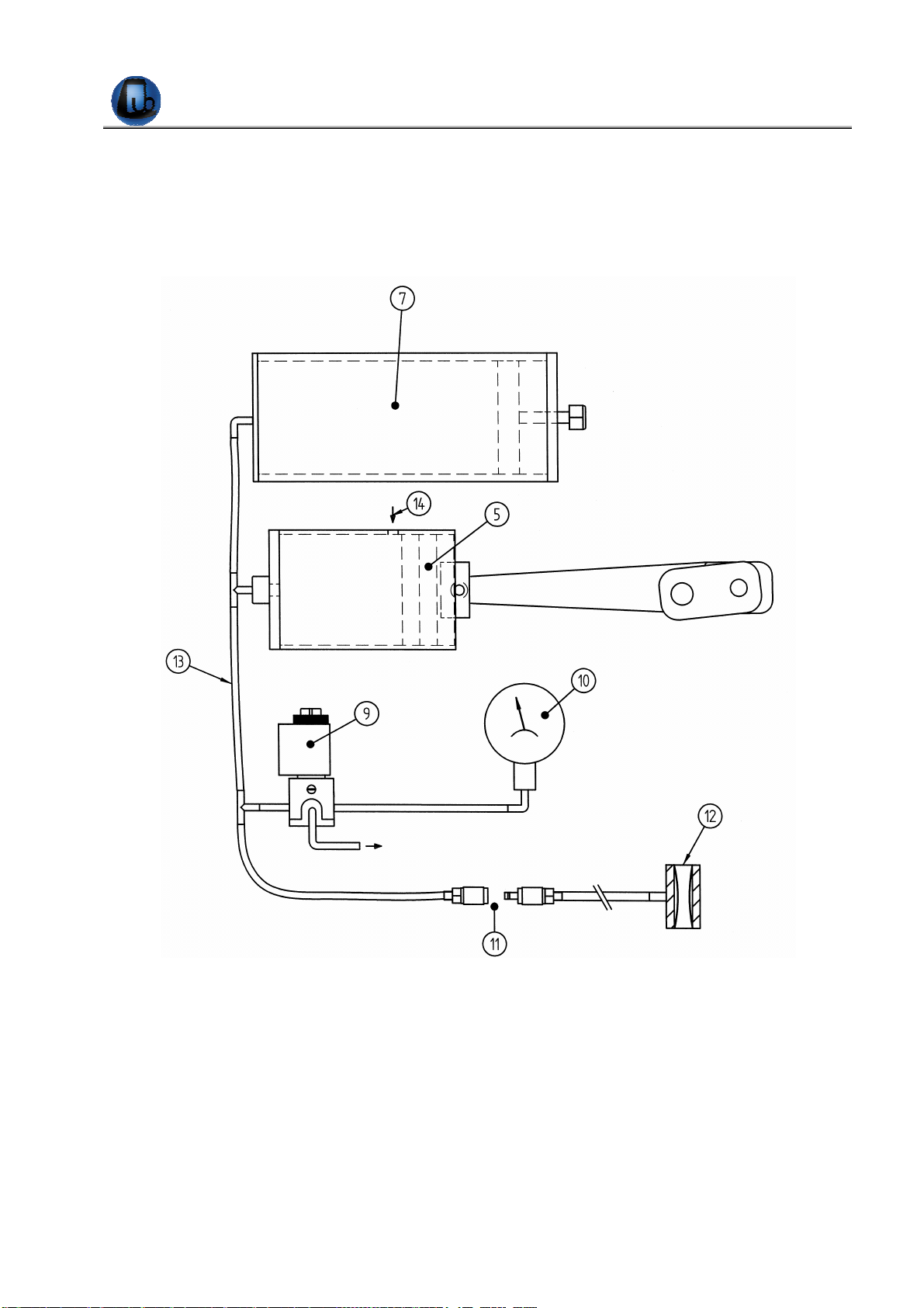
Instrument Description
Pressure is transmitted to the tail cu; as soon the cu
pressure exceeds the diastolic pressure and starts to nar-
row the tail artery, the amplitude of the recorder pulse
wave gradually decreases until the artery is completely
constricted (ischemic), the graph becoming a straight line.
This point indicates the maximum internal pressure of the
artery (systolic pressure) on the paper grid, on which the
actual pressure of the system is digitally printed in 10
mm Hg steps.
At the end of the recording a second pressure measure-
ment can be started, with decreasing pressure. The sy-
stolic pressure is indicated, this time, by the return of the
pulse tracing.
The animal pulse rate can be assessed in real time by a
pulse rate counter which picks the signal from the pulse
transducer.
BLOOD PRESSURE, VITAL FUNCTIONS
Cat. No. 58500 for Rats
Cat. No. 58600 for Mice
Cat. No. 58550 for Rats & Mice
INDIRECT MEASURING & RECORDING OF THE
SYSTOLIC AND DIASTOLIC PRESSURE
IN UNANAESTHETIZED RATS & MICE
Main Features
l graphic printer
l graphic display
l analog output to digital recorders
l pulse transducers of superior performances
l analogue & digital recording of all experiment phases
l reliable pressure generator, providing smooth, stepless
pressure build-up
Ugo Basile: more than 10,000 citations

UGO BASILE S.R.L.
BIOLOGICAL RESEARCH
APPARATUS
CHECK-LIST
CAT: 58500 BP Recorder for Rat
CAT: 58600 BP Recorder for Mouse
CAT: 58700 BP Recorder for Dog
CLIENTE / CUSTOMER______________________________________________
No. Ordine / Order No. ____________________ Data / Date____/_____/______
UB code CAT.No.
√
Q.ty DESCRIPTION
CHECK THAT THE VOLTAGE SELECTOR & THE FUSES CORRESPOND TO WHAT INDICATED IN THE RATING MARKS
E-WP 008 EUROPA
E-WP 008-1 U.S.A.
E-WP 008-2 1
MAINS CABLE U.K
M-LM 303 58000-301 1 DUST COVER
58000-301 1 INSTRUCTION MANUAL
E-FT 002-1 2 FUSES FOR 115V (T 630 MA)
E-FT 004-1 2 FUSES FOR 230 V (T 315 MA)
A-CA 58000-305 58000-305 2 PAPER ROLLS
52050-08 1 CD CUB
52010-320 1 USB CONVERTER TO SERIAL PORT
52010-322 1 CONNECTING CABLE 9 TO 9 PIN
STANDARD SET
FOR 58500 58000-508
58000-613
58000-345 1
1
1
8 mm PULSE PICK-UP
13 mm PRESSURE CUFF WITH SET OF O-RINGS & SET OF 5 MEMBRANES
RAT HOLDER, 50 mm
STANDARD SET
FOR 58600 58000-503
58000-606
58000-343 1
1
1
3 mm PULSE PICK-UP
6 mm PRESSURE CUFF WITH SET OF O-RINGS & SET OF 5 MEMBRANES
MOUSE HOLDER 30 mm DIAM.
STANDARD SET
FOR 58700 58000-518
58000-620 1
1 18 mm PULSE PICK-UP
20 mm PRESSURE CUFF WITH SET OF 2 O-RINGS & SET OF 5 MEMBRANES
ADDITIONAL OPTIONAL ACCESSORIES
58000-504 4 mm PULSE PICK-UP MOUSE
58000-505 5 mm PULSE PICK-UP RAT
58000-506 6 mm PULSE PICK-UP RAT
58000-507 7 mm PULSE PICK-UP RAT
58000-509 9 mm PULSE PICK-UP RAT
58000-609 9 mm PRESSURE CUFF FOR RAT
58000-624 24 mm PRESSURE CUFF FOR DOG
58000-344 RAT HOLDER 40 mm DIAM.
58000-346 RAT HOLDER 60 mm DIAM.
58000-350 RAT SIMULATOR
DATE / / Serial No. PREPARATO DA / PACKED BY
Set for 115V 50 Hz 230V 50 Hz 115V 60 Hz 230V 60 Hz
IMPORTANT/IMPORTANTE:
Check the shipment for completeness immediately after receipt: should you find any discrepancy, please fill in the following part and
transmit it to our fax No. +39 0332 745488
Al ricevimento della merce controllate che la spedizione sia completa: in caso di discrepanza, completate il formulario di seguito ri-
portato ed inviatelo al nostro fax No. 0332 745488
FROM: Name
Company/Institution
DATE REF.
NOTES
MOD.04 REV 0

UGO BASILE - ITALY Page i
47105 Instruction Manual (Rev. 2)
C O N T E N T S
1INTRODUCTION 1
2INSTRUMENT DESCRIPTION 2
2.1 PRESSURE GENERATOR SYSTEM 2
2.2 COMMAND OVERVIEW 4
2.3 CHART RECORDER 5
2.4 TAIL CUFFS 6
2.5 PULSE TRANSDUCERS 6
2.6 ANIMAL RESTRAINERS 7
2.7 OPTIONAL ANIMAL HEATER /SCANNER 7
3DATA ACQUISITION 8
4INSTALLATION 8
4.1 UNPACKING &PRELIMINARY CHECK 8
4.2 NOTES ON THE INSTRUCTION MANUAL 9
4.3 BEFORE APPLYING POWER 9
4.3.1 MAINS SWITCH 9
4.3.2 FUSE HOLDER &VOLTAGE SELECTOR 10
4.3.3 MAINS CORD 10
4.4 CONNECTIONS 10
4.5 ADDITIONAL SAFETY CONSIDERATION 11
5PRELIMINARY 11
5.1 PRE-WARMING THE ANIMAL (RAT &MOUSE) 11
5.2 RESTRAINING THE RODENT 12
5.3 CONDITIONING THE RODENT 12
5.4 SWITCHING ON13
5.5 INITIAL “DRY RUN” 13
6OPERATION 14
6.1 MODE MENU 14
6.1.1 MEASUREMENT SELECTION 14
6.1.2 SPEED SELECTION 15
6.1.3 ANIMAL SELECTION 15
6.1.4 SET REVERSE PRESSURE 16
6.1.5 SET REVERSE TIME 16
7TEST MENU 16

UGO BASILE - ITALY Page ii
47105 Instruction Manual (Rev. 2)
7.1 AUTOMATIC MEASUREMENT 17
7.2 MANUAL MEASUREMENT 17
7.3 STARTING THE PRESSURE MEASUREMENT 18
8CALIBRATION 20
9DATA PRINT-OUT AND OUTPUT TO THE PC 21
9.1 HOW TO SET THE DATA OUTPUT 21
9.2 INSTRUMENT ADDRESS AND BAUD-RATE 22
9.3 HOW TO SET A CUSTOMIZED EXPERIMENTAL CONFIGURATION 23
9.3.1 SEQUENCE NUMBER 23
9.3.2 ANIMAL GENDER 24
10 QUICK SETTING OF THE BP RECORDER 24
11 MEMORY MANAGEMENT 25
11.1 MEMORY RESET 26
11.1.1 “MEMORY FULL”MESSAGE 27
11.2 SETTING TIME &DATE 27
11.3 DISPLAY CONTRAST 28
12 MAINTENANCE 28
12.1 ELECTRICAL 29
12.2 REPLACING A LEAKY PRESSURE CUFF MEMBRANE 29
12.3 REPLACING THE PAPER ROLL 29
12.4 LONG INACTIVITY 30
12.5 CUSTOMER SUPPORT 30
13 ORDERING INFORMATION 31
13.1 AVAILABLE PULSE PICK-UPS 31
13.2 AVAILABLE TAIL CUFFS 32
13.3 AVAILABLE HOLDERS 32
13.4 ACCESSORIES AND CONSUMABLES 32
13.5 OPTIONAL 32
13.6 SPECIFICATIONS 33
14 BIBLIOGRAPHY 33

FIGURE INDEX
Figure 1 “Pressure Generator” ........................................................................................................................2
Figure 2 “Pneumatic Circuit”............................................................................................................................3
Figure 3 “Sample of a Graph”..........................................................................................................................4
Figure 4 “Front Panel” .....................................................................................................................................4
Figure 5 “Tail Cuff”...........................................................................................................................................6
Figure 6 “Pulse Transducer”............................................................................................................................6
Figure 7 “Rat Holder”.......................................................................................................................................7
Figure 8 “Rat Scanner”....................................................................................................................................8
Figure 9 “Power Module”.................................................................................................................................9
Figure 10 “Back Panel”..................................................................................................................................10
Figure 11 “Paper Roll”...................................................................................................................................30

UGO BASILE – ITALY Page 1
Series 58000 Instruction Manual (Rev.1)
BP RECORDER
FOR INDIRECT MEASURING AND RECORDING OF BLOODLESS PRESSURE IN UN-
ANAESTHETIZED RATS AND MICE
SERIES 58000
1INTRODUCTION
Our BP Recorders series 58000 have been conceived to provide an objective precise
recording of the systolic and diastolic pressure of rodents.
This new model, housed in an attractive cabinet of original design, is provided with:-
•graphic printer
•graphic display
•serial port RS232C
•analog output for direct connection to most digital recorders (as PowerLab) for
data acquisition and management
Its paramount features are:-
i) a set of pulse transducers of superior performance
ii) a reliable pressure generator which provides a very smooth (stepless) pres-
sure build-up
iii) an analog and digital recording of all the phases of the experiment
The 58500 combines together three main systems:-
1) pressure generation-pressure monitoring system
2) pulse amplifier
3) thermal-array analog & digital recording unit
and two auxiliary systems:-
4) pulse rate measuring and recording
5) microprocessor controlled functions of self diagnosis, calibration, signal filter-
ing, signal storage

UGO BASILE - ITALY Page 2
Series 58000 Instruction Manual (Rev.1)
2INSTRUMENT DESCRIPTION
Figure 1 “Pressure Generator”
2.1 Pressure Generator System
A geared motor (1), via a crank-link-gudgeon (2, 3, 4) causes the forward and reverse
motion of a piston (5) into a stationary cylinder (6), see Figure 1 “Pressure Generator”.
This pressure generating mechanism is fastened to a sturdy aluminium plate (8).
The pressure is transmitted via an appropriate piping (13) to an expansion vessel (7), a
blow-out valve (9), a pressure gauge (10) and the tail cuff (12) through the pneumatic
connection (11), see Figure 2 “Pneumatic Circuit”.
The cuff pressure increases until it exceeds the diastolic pressure and starts to constrict
the tail artery (arteria caudalis). The amplitude of the recorded pulse wave decreases un-
til the artery is completely constricted (ischemic) and the graph becomes a straight line.
When the operator selects the “compression measurement” only, a point indicates on the
paper grid the maximum internal pressure of the artery (systolic pressure).

UGO BASILE - ITALY Page 3
Series 58000 Instruction Manual (Rev.1)
The piston motion reverses and the decompression phase begins. The systolic pressure
is indicated, this time, by the return of the pulse trace.
The pulse rate of the animal is automatically assessed in real time by a pulse rate
counter which picks the signal from the pulse transducer.
Figure 2 “Pneumatic Circuit”
In both compression and decompression runs, even the diastolic, if selected, is re-
corded as the pressure at which the pulse shows an unmistakable transition from steady
to decreasing amplitude.
See Figure 3 “Sample of a Graph” and more details about graph and captions on para-
graph 7.3-Starting the Pressure Measurement.
You will notice the pressure indications are sets of three digits, e.g., 070 – 130 – 180,
marked on the lower edge of the recording chart in vertical pattern, for economy of
space, as in the Chinese signs.

UGO BASILE - ITALY Page 4
Series 58000 Instruction Manual (Rev.1)
Figure 3 “Sample of a Graph”
Note the port (14) on the side of the cylinder which enables the pressure run to start at
room pressure. The blow-out valve allows the operator to depressurize the system and to
interrupt and abort the trial at any time, whereupon the trial is brought to an end. A mis-
take manoeuvre and the struggling of the animal are the most common reasons to abort
the trial.
2.2 Command Overview
Figure 4 “Front Panel”
On the left side, we see the Chart Recorder, see 2.3-Chart Recorder, which lacks any manual
control, knobs, keys, etc., except the miniature black toggle which opens the chart door.

UGO BASILE - ITALY Page 5
Series 58000 Instruction Manual (Rev.1)
In fact, the recorder status and functions are set-up automatically and visualized via the display.
The dedicated keys
RED (DECOMPRESSION, which releases the pneumatic system and causes the
piston to speed back to its starting point, when depressurization is neces-
sary, see paragraph 2.4-Tail Cuffs).
BLUE (START/REVERSE, see paragraph 7.3-Starting the Pressure Measure-
ment)
and the four functional keys
F1-F2-F3-F4
are the only operational commands.
The display and the functional keys combine to program the trial parameters selected by the op-
erator, to communicate the status of the experiment, any warning message, etc., see following
subheadings.
The upper rectangular window brings the linkage in sight and reassures the operator that the
pressure generator is doing its job.
2.3 Chart Recorder
This high-resolution, 50mm, real-time thermal printer of GSI LUMONICS, located on the
left side of the upper panel, has been selected as it offers a number of new features, in-
cluding warning messages to notify the user of undesirable conditions, thus preventing
errors.
See Figure 11 “Paper Roll”, self-explanatory on what concerns the replacement of the
chart roll.
The XE-50 communicates through a serial interface at 115,000 bits per second: when in
recorder mode it prints a simultaneous real-time waveform along with background grid,
text, and graphics.
The table below lists some specs. of this remarkable chart recorder:-
Printing method : direct, thermal
Print resolution : 600 dots per 25 mm
Drive type : stepper motor
Chart specs. : 2-inch thermal roll paper, 100 ft length
Chart speed : selectable
Chart skew : ± 0.5 mm maximum over any 10 s interval, after first 150
Accuracy : ± 2%

UGO BASILE - ITALY Page 6
Series 58000 Instruction Manual (Rev.1)
2.4 Tail Cuffs
The rat and mouse tail cuffs, available in
different diameters (see 13.2-Available
Tail Cuffs) are of simple and straightfor-
ward design: they combine a sturdy short
plastic-tube, a rubber membrane and two
O-rings (see 13.4-Accessories and Con-
sumables, for spares) to seal the annular
pressure chamber.
The cuff is provided with a stretch of Tygon
tube featuring a pneumatic snap-in connec-
tor to couple it to the BP Recorder.
See also paragraph 12.2-Replacing a
Leaky Pressure Cuff Membrane for fitting
and replacing the membranes. Figure 5 “Tail Cuff”
Incidentally, to free the animal from the tail-cuff without hurting it or damaging the rubber
membrane, requires the cuff to be deflated.
To depressurize, push the red key DECOMP: this causes the solenoid valve (9) to open,
releasing the pneumatic system, and the piston to speed back to its starting point.
2.5 Pulse Transducers
The pulse transducer, or pulse
pick-ups, available in different
diameters (see 13.1-Available
Pulse Pick-ups) are basically
piezoceramic rings.
They fit the tails of the animals
and are “stressed” by the
rhythmical expansion caused
by the systolic waves.
It is known that the stress
causes a piezoelectric ele-
ment to generate a propor-
tional voltage; in our pulse
transducers this voltage is led
to the amplifier by a miniature
coaxial cable.
Figure 6 “Pulse Transducer”
An expendable foam rubber ring reduces the mechanical shocks brought about by the
tail movements and thus minimizes any spurious signals.
RUBBER
MEMBRANE
O-RING
GROOVES

UGO BASILE - ITALY Page 7
Series 58000 Instruction Manual (Rev.1)
2.6 Animal Restrainers
Convenient animal restrainers are provided with the standard package. Our models are
particularly suitable, see Figure 7 “Rat Holder”, being purposefully designed for this task,
as they feature:-
a) a conical “muzzle” to confine the animal head
b) availability in 3 different diameters for rat and one for mouse, to fit various animal
sizes (see 13.3-Available Holders).
c) telescope-adjustable length
d) a quick fit/release back lid provided with an ample U-shaped tail slot
e) capability of dissipating the rat body heat by a suitable combination of ventilation
slots, selection of heat conductive materials, etc.
Figure 7 “Rat Holder”
See also paragraph 5.2-Restraining the Rodent.
2.7 Optional Animal Heater /Scanner
The 58000-850 Rat Scanner is a compact temperature controlled “cupboard” which can
house 5 rats, each in its individual holder, for pre-warming the animals, see paragraph
5.1, and scanning their BP measures.
The tail cuff and pulse pick-up can be positioned on the animal tail.
A double switch (electrical/pneumatical) enables the operator to connect the holders in
sequence to the BP Recorder, to “scan” the blood pressure of up to 5 rodents.

UGO BASILE - ITALY Page 8
Series 58000 Instruction Manual (Rev.1)
A more economical version, Cat.
58000-845, without the pneu-
matic/electrical scanning provision,
is also available, when only pre-
warming is required.
The 58000-840, designed for
mice, has the same dimensions,
but it accommodates 6 mouse
holders.
See paragraph 13.5-Optional.
Figure 8 “Rat Scanner”
3DATA ACQUISITION
The 58500 BP Recorder is microprocessor controlled and features direct PC output. Internally-
stored data can be routed via 9-pin D-type connector to the PC serial port (RS232) see para-
graph 9-DATA PRINT-OUT AND OUTPUT TO THE PC.
Serial communication between 58500 BP Recorder and an IBM (or compatible) PC is controlled
by Ugo Basile Win-DAS Software Cat. 52010 supplied as optional. See 13.5-Optional.
The 52010 is a Windows®based Data Acquisition Software Package, which enables the
research worker to store the data into individual files, ready to be easily managed by
most statistical analysis packages available on the market. Ask for details: a free demo
diskette is available!
4INSTALLATION
4.1 Unpacking & Preliminary Check
Check the contents of the shipment for completeness, packing list to hand, and visually
inspect the instrument as soon you take it out of the packaging. Use the Check List sup-
plied.
If the instrument is damaged or, after having tested it, fails to meet rated performances,
notify the carrier and our company immediately.

UGO BASILE - ITALY Page 9
Series 58000 Instruction Manual (Rev.1)
P
Pr
ro
ot
te
ec
ct
t
t
th
he
e
e
en
nv
vi
ir
ro
on
nm
me
en
nt
t!
!
Dispose of packaging properly, according to existing and ap-
plicable waste management rules and regulations.
4.2 Notes on the Instruction Manual
The BP Recorder Instruction Manual included in accessory package is necessary for the
correct installation and operation of the instrument.
We recommend keeping the manual in good condition, ready to be consulted by the
qualified personnel who use the instrument.
Free of charge copies of the instruction manual are available upon request: please con-
tact our service department (see paragraph 12.5- Customer Support) specifying the se-
ries number of your instrument.
4.3 Before Applying Power
Position the instrument on a stable and flat bench or table surface.
Figure 9 “Power Module”
Take a look at the Power Module, on the back of the instrument, which encompasses –
from left to right - the inlet connection of the mains cord, the mains switch and the fuse
holder/voltage selector.
4.3.1 Mains Switch
This two-pole toggle switch, which complies with international safety standards, provides a visual
cue, meaning:-
•OFF when pressed to the “O” side
•ON when pressed to the “I” side

UGO BASILE - ITALY Page 10
Series 58000 Instruction Manual (Rev.1)
4.3.2 Fuse Holder & Voltage Selector
The fuse holder comprises two fuses, one on the live, and the other on the neutral. For operation
at 230-240 Volts, we recommend 315 mA timed “slow blow” fuses (type T315). Use 630 mA
fuses (type T630) for operation at 115 Volts.
The fuse holder also embodies the Voltage Selector. Make sure that the label visible in the win-
dow indicates the correct voltage (i.e., the voltage of your mains).
To replace the fuses and/or change the selected voltage, see paragraph 12.1-Electrical.
4.3.3 Mains Cord
It is a standard cable, Cat. # E-WP008. Make sure your power outtake is provided with a reliable
ground connection, see also 4.4 & 4.5.
4.4 Connections
Connect the mains cord to a power outtake, provided with a reliable earth connection.
Beside the power module described in paragraph 4.3, the BP Recorder back panel encompasses
the following connectors, from left to right:-
Figure 10 “Back Panel”
SERIAL INTERFACE: this delta 9-pin connector enables the operator to connect the in-
strument to the serial port RS232C of the PC, see paragraph 3-
DATA ACQUISITION.
PRESSURE SIGNAL
(ANALOGIC):
PULSE SIGNAL:
these connectors are useful to route both pressure and pulse
signals to CRT (oscilloscope), chart recorder or PC (via a data
acquisition system)

UGO BASILE - ITALY Page 11
Series 58000 Instruction Manual (Rev.1)
PULSE TRANSDUCER: for connection of the selected transducer, see paragraph 2.5.
PNEUMATIC
CONNECTION: for connection of the selected cuff, see paragraph 2.4.
4.5 Additional Safety Consideration
a. Place your BP Recorder on a steady flat surface.
b. Do not obstruct free and comfortable access to the power module.
c. Use original accessories and spare parts only, see also paragraph 13-
ORDERING INFORMATION.
d. Immediately disconnect and replace an accidentally damaged mains cable.
e. Do not operate the BP Recorder in hazardous environments or outside pre-
scribed environmental limitations (i.e. 10°C / +40°C, 95% relative humidity,
non-condensing).
f. Do not spray any liquid on the connectors.
UGO BASILE DOES NOT ACCEPT ANY RESPONSIBILITY FOR PROB-
LEMS OR HARM CAUSED TO THINGS OR PERSONS ARISING FROM:
♦INCORRECT ELECTRICAL SUPPLY.
♦INCORRECT INSTALLATION PROCEDURE.
♦INCORRECT OR IMPROPER USE OR, IN ANY CASE, NOT IN AC-
CORDANCE WITH THE PURPOSE FOR WHICH THE INSTRUMENT
HAS BEEN DESIGNED AND THE WARNINGS BROUGHT TO YOUR
ATTENTION IN THE INSTRUCTION MANUAL SUPPLIED WITH THE
INSTRUMENT.
♦REPLACEMENT OF ORIGINAL COMPONENTS, ACCESSORIES OR
PARTS WITH OTHERS NOT APPROVED BY THE MANUFACTURER.
♦SERVICING CARRIED OUT BY UNAUTHORIZED PERSONNEL.
5PRELIMINARY
5.1 Pre-warming the Animal (Rat & Mouse)
Place the animal in a warming cupboard, at about 29-30°C for at least 30 minutes, in order to
cause a sufficient vasodilation in the caudal artery. We recommend our models, purposefully de-
signed for this task, see 2.7-Optional Animal Heater /Scanner.
Some researchers feel that in this way the vasodilation of the whole vascular system will inevita-
bly cause a “pressure drop”. This pressure drop takes place in all animals and consequently the
reliability of a pressure screening should not be severely affected. Admittedly, this reasoning may
leave some scientists uncomfortable about the artefact he/she feels it may impair the experiment.

UGO BASILE - ITALY Page 12
Series 58000 Instruction Manual (Rev.1)
As alternative, it is suggested to prewarm at lower temperature, say, 26-27°C which, after all, is
not worse than a hot Summer day, and then apply local heating.
Once the animal is restrained in its harness, apply on the protruding tail the heat source, which
can be an infrared bulb, a heating blanket or both.
Care should be taken to avoid overheating which may cause the animal a severe discomfort and
consequent struggling, etc. A warm jacket-tube in which the tail is inserted has proven to be
good.
Bear in mind that the vasodilation which makes the pulse “audible” to the transducer is a thresh-
old process. In particular, when the local heating method is followed, the pulse may be totally
missing at the “TEST interrogation” and pops out loud and clear twenty seconds later.
Once a satisfactory vasodilation is achieved, the heat source can be removed or reduced. A
minimum of practice (and persistence!) will overcome all problems.
According to our knowledge, every researcher using the BP Recorder has perfected the tech-
nique, adding each his/her personal touch to optimize technique for lab or application.
5.2 Restraining the Rodent
Basically, rats and mice are placed into suitable harnesses from which the tail protrudes. The rat
and mouse holders available on the market or already in use at your laboratory may prove to be
convenient.
Our models, being purposefully designed for this task, are particularly suitable, see 13.3-
Available Holders and Figure 7 “Rat Holder”.
5.3 Conditioning the Rodent
Some research workers think advisable to carry out some kind of “conditioning”, before starting
the blood pressure measurement.
In other words, the animals should be kept 3-4 minutes in the restrained conditions, their tails fit-
ted with cuff and transducer, better if the exercise is repeated 2-3 times a day. It is obvious they
will behave in a more relaxed way, in particular from the cardio-vascular perspective, when the
“real thing” will eventually take place!
Operate with patience and remember that more patience and longer familiarization time are re-
quired when handling mice. These small creatures seem to be constantly in motion, twisting and
turning, particularly when you confront them with a fresh mouse holder.

UGO BASILE - ITALY Page 13
Series 58000 Instruction Manual (Rev.1)
5.4 Switching On
Switch on the instrument. Momentarily, the display will read
“V01” (firmware version 01) according to the following pic-
ture:
The top line (now 000) indicates the actual pressure in the
tail cuff.
The second line shows the heart rate in pulses per minute.
This figure can be 000, or a value recorded in a previous
experiment may be displayed.
The caption below the second line shows the logo, the manufacturer’s name, the firmware ver-
sion (actually V01) and the catalogue number of the instrument.
The bottom line illustrates the key functions.
Depress the key F4 (ESC); the following displays will appear in loop-mode succession:-
You will notice a change only in the 3rd and 4th line which
form a small-type double string. The top string shows, in or-
der, systolic, diastolic pressure and heart rate in the com-
pression phase.
The bottom string shows the same data, in the same se-
quence, but related to the decompression phase.
The M01 characters represent complementary information,
which will be described later on.
By depressing the F4 key again the display shows the present time and date, once more and the
two mice (logo of our flyers) show up!
Our attention is now directed to the key functions:-
•OPR (OPERATION)
•FNC (FUNCTION)
•MEM (MEMORY)
•ESC (ESCAPE)
5.5 Initial “Dry Run”
A “dry run” is advisable, to get familiar with the instrument, neglecting for the moment the animal
which will otherwise drive all available attention.
Connect both the selected pulse transducer and pressure cuff, see paragraph 4.4-Connections.
This manual suits for next models
2
Table of contents
Other UGO BASILE Medical Equipment manuals
Popular Medical Equipment manuals by other brands

ResMed
ResMed AirFit N30 user guide

Boston Scientific
Boston Scientific RELIANCE 4-FRONT Series Physician's lead manual

human care
human care Levanto user manual

Phcbi
Phcbi MBR-305GR operating instructions

Avizia
Avizia CA310 User's installation guide

Care Fusion
Care Fusion Snowden-Pencer 88-5225 instructions