Wireless Gateway with Siren
Wireless Gateway with SirenWireless Gateway with Siren
Overview
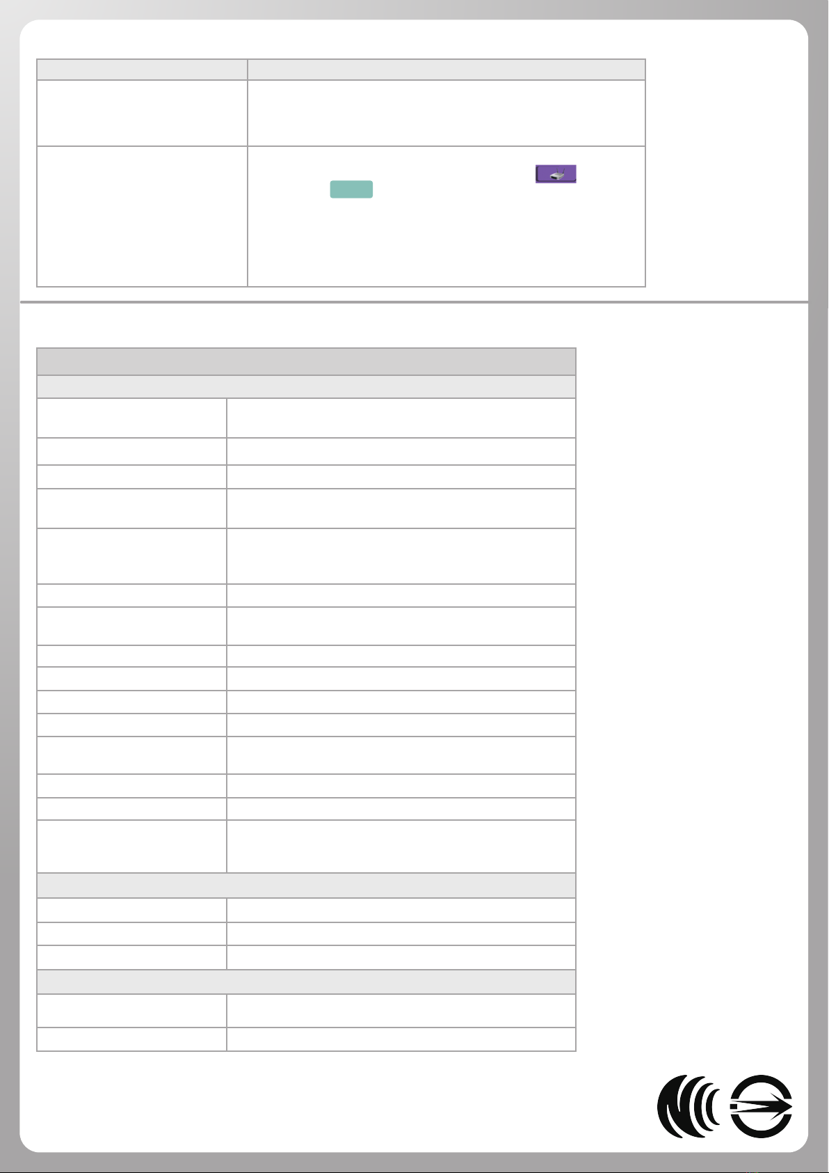
Name : Wireless Gateway with Siren
Power : (DC) 5V power
Dimension : 100 x 90 x 34.5 mm
Accessories : Adapter, Antenna, Double-side Tape
Names of Parts
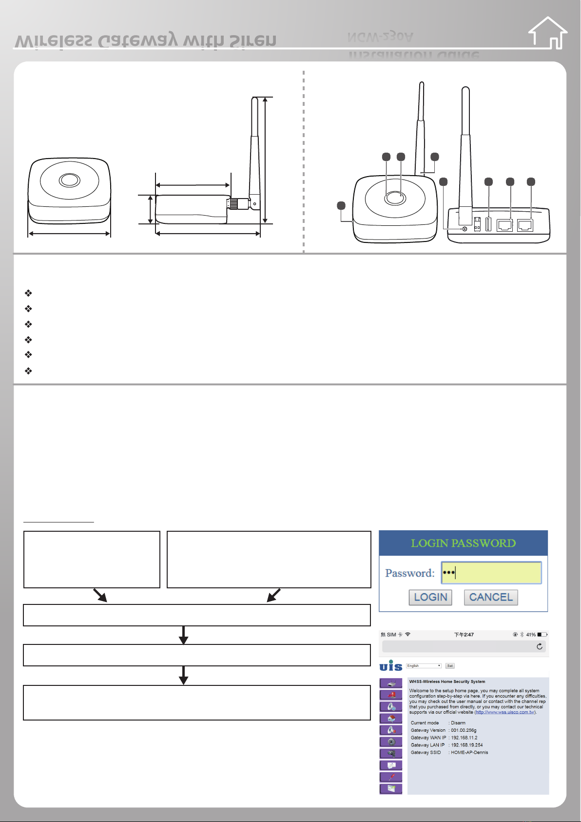
1. Buzzer
2. SET Button
3. LED indicator
4. Antenna
5. DC 5V
6. USB
7. WAN
8. LAN
Features
Wireless transmission, receiving, control and detect signal devices, real time indication
External network via 4G module or WAN cable
Intranet enable to connect wired IPCAM or WIFI
Automatic joining or manual joining by button
Build-in buzzer for voice notication
Two color LED indicator and button function
Installation
Note: We suggest to use auto joining all device at the rst time. Please refer to APP Quick Installation Guide.
Device Installation and Manual Joining
1. Select the proper location for installation.
2. Plug in adaptor, one side plug in the device, the other side to the wall socket.
3. After plug in the adapter, the indicator red light blinks 10seconds afterward. It starts to blink green light, wait for 40 seconds.
It boots up completely.
4. Basic Settings: Use the computer to link the gateway. There are two methods (Cable & WiFi).
Please launch browser on your PC
Input URL http://192.168.19.254 then press ” Enter “button
When appears “password input dialog”, please input 123 in the PASSWORD eld.
Press ” LOGIN”button, then you will see the basic setting page.
5. Press the top button of the device, indicator red & green light will blink alternatively,
then the system enter sensor automatic joining and IP CAM WPS joining process.
6. The indicator red light will blink while alarm occurred. Press top button of the device
once, then the alarm can be disabled.
Installation Guide
NGW-230A
100mm
34.5mm
153mm
126mm
90mm
ON
WAN LAN
1 2
Cable
It links the computer and LAN
port of gateway. Please set the
same website:192.168.19.XXX
WiFi
Use WIFI to link the Gateway. Original name of
WIFI is on the sticker (SSID) under the gateway.
password: 1234567890
192.168.19.254
2 3 4
1
5 6 7 8