Ultra-Aire 100V User manual

The Ultra-Aire 100V is a whole house ventilating dehumidifier that
is integrated into the heating and cooling system to provide the
ultimate in comfort, health and property protection through:
• Dehumidification
• Fresh Air Ventilation (Optional)
• Air Filtration
TS-600 12/27/16
P/N: 4029710 Serial No.: Install Date:
Sold by:
HVAC Installer: Please Leave Manual for Homeowner
Installation Instructions
INSTALLATION BY A HVAC PROFESSIONAL IS RECOMMENDED
YEAR
FULL WARRANTY
YEAR
FULL WARRANTY

Safety Instructions ...................................................................... 3
Specifications .............................................................................. 4
Optional Accessories................................................................... 5
Dehumidifier Set Up .................................................................... 6
Attaching Duct Collars................................................................. 7
Electrical Requirements .............................................................. 8
Drain Installation ......................................................................... 9
Ducting to HVAC Systems.......................................................... 10
Recommended HVAC System Installations ........................................ 11
Alternative HVAC System Installations................................................ 12
Recommended Multiple HVAC Systems Installation .......................... 14
No Existing Ductwork Installation ....................................................... 15
Fresh Air Ventilation .................................................................. 16
Controls ..................................................................................... 18
Air Filtration............................................................................... 20
Service....................................................................................... 22
Troubleshooting................................................................................... 23
Warranty .................................................................................... 25
TABLE OF CONTENTS
Ultra-Aire is committed to manufacturing quality products. To maintain
our standards, product specifications may change without notice.
4201 Lien Rd. Madison, WI 53704
1-800-533-7533
www.Thermastor.com | www.Ultra-Aire.com
© 2015 Therma-Stor LLC

3
www.Ultra-Aire.com | 1-800-533-7533 Ultra-Aire 100V Installation Instructions
SAFETY INSTRUCTIONS
WARNING!
THIS SYMBOL MEANS IMPORTANT INSTRUCTIONS. FAILURE TO HEED THEM
CAN RESULT IN SERIOUS INJURY OR DEATH.
READ THE INSTALLATION, OPERATION AND MAINTENANCE INSTRUCTIONS CAREFULLY
BEFORE INSTALLING AND OPERATING THIS DEVICE. PROPER ADHERENCE TO THESE
INSTRUCTIONS IS ESSENTIAL TO OBTAIN MAXIMUM BENEFIT FROM YOUR ULTRA-AIRE
WHOLE HOUSE VENTILATING DEHUMIDIFIER.
CAUTION!
THIS SYMBOL MEANS IMPORTANT INSTRUCTIONS. FAILURE TO HEED THEM
CAN RESULT IN INJURY OR MATERIAL PROPERTY DAMAGE.
Registrations
The Ultra-Aire 100V conforms to unified standard UL 60335-2-40 and CSA standard C22.2.60335-2-40.
CAUTION!
READ ALL INSTRUCTIONS BEFORE BEGINNING INSTALLATION.
ALWAYS USE CAUTION AND WEAR CUT RESISTANT GLOVES WHEN HANDLING SHEET
METAL.
IMPROPER INSTALLATION MAY CAUSE PROPERTY DAMAGE OR INJURY.
INSTALLATION, SERVICE, AND MAINTENANCE MUST BE PERFORMED BY A QUALIFIED
SERVICE TECHNICIAN.
DEHUMIDIFIER IS HEAVY. HANDLE WITH CARE AND FOLLOW INSTALLATION INSTRUCTIONS.
DO NOT USE IN POOL APPLICATIONS, OR WARRANTY WILL BE VOID.
NEVER OPERATE A UNIT WITH A DAMAGED POWER CORD. IF THE POWER CORD IS
DAMAGED, IT MUST BE REPLACED BY THE MANUFACTURER, ITS SERVICE AGENT, OR A
SIMILARLY QUALIFIED PERSON IN ORDER TO AVOID A HAZARD.
THIS APPLIANCE IS NOT INTENDED FOR USE BY PERSONS (INCLUDING CHILDREN) WITH
REDUCED PHYSICAL, SENSORY OR MENTAL CAPABILITIES, OR LACK OF EXPERIENCE
OR KNOWLEDGE, UNLESS THEY HAVE BEEN GIVEN SUPERVISION OR INSTRUCTION
CONCERNING THE USE OF THE APPLIANCE BY A PERSON RESPONSIBLE FOR THEIR
SAFETY. CHILDREN SHOULD BE SUPERVISED TO ENSURE THAT THEY DO NOT PLAY WITH
THE APPLIANCE.
WARNING!
120 VOLTS MAY CAUSE SERIOUS INJURY FROM ELECTRIC SHOCK.
DISCONNECT ELECTRICAL POWER BEFORE STARTING INSTALLATION OR
SERVICING, AND LEAVE POWER DISCONNECTED UNTIL INSTALLATION OR
SERVICE IS COMPLETED.

4Ultra-Aire 100V Installation Instructions www.Ultra-Aire.com | 1-800-533-7533
SPECIFICATIONS
Part Number: 4029710
Blower: 255 CFM @ 0.0" WG
215 CFM @ 0.2" WG
170 CFM @ 0.4" WG
Power: 700 Watts @ 80°F and 60% RH
Supply Voltage: 115 VAC – 1phase – 60 Hz
Current Draw: 6.4 Amps
Energy Factor: 2.95 L/kWh
Operating Range: 56°F Min, 95°F Max (Inlet Air Temperature)
34°F Min, 135°F Max (Outside Cabinet)
Sized for: Up to 2,500 Sq. Ft. - Typical
Water Removal at: 80°F and 60% RH 70°F and 60% RH
Capacity: 110 pints/day 90 pints/day
Efficiency: 6.2 Pints/kWh 6.0 Pints/kWh
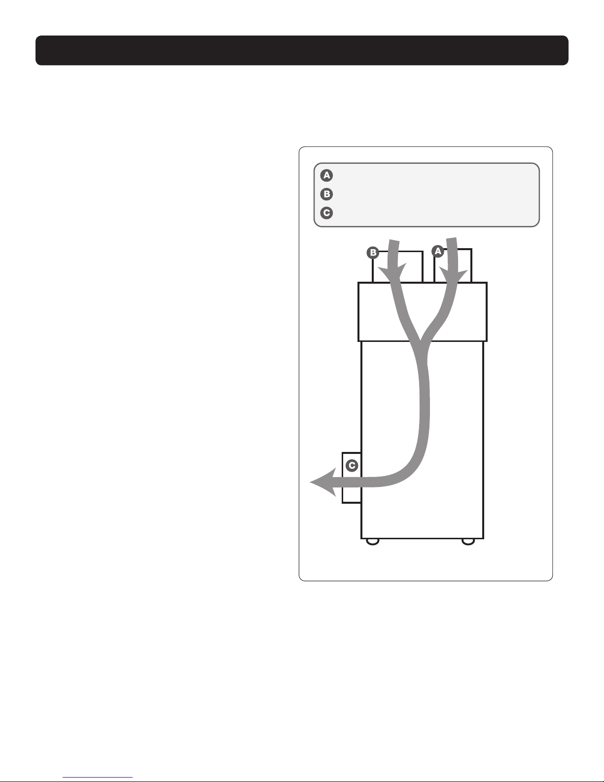
Duct Connections: 6" Round Inlet; 8" Round Inlet; 8" Round Outlet
Air Filter: MERV-11, Standard Pleat
Efficiency: 65% ASHRAE Dust Spot
Size: 16" x 20" x 2"
Optional Air Filter: MERV-14, Embossed Pleat
Efficiency: 95% ASHRAE Dust Spot
Size: 16" x 20" x 4"
Power Cord: 9', 115 VAC, Ground
Internal Insulated Cabinet: No
Drain Hose: 6’ Direct Gravity Drain Hose (9/16” ID x 3/4” OD)
Refrigerant Type: R410A (Refer to manufacturers label for more information)
Refrigerant Amount: 1 lb., 9 oz.
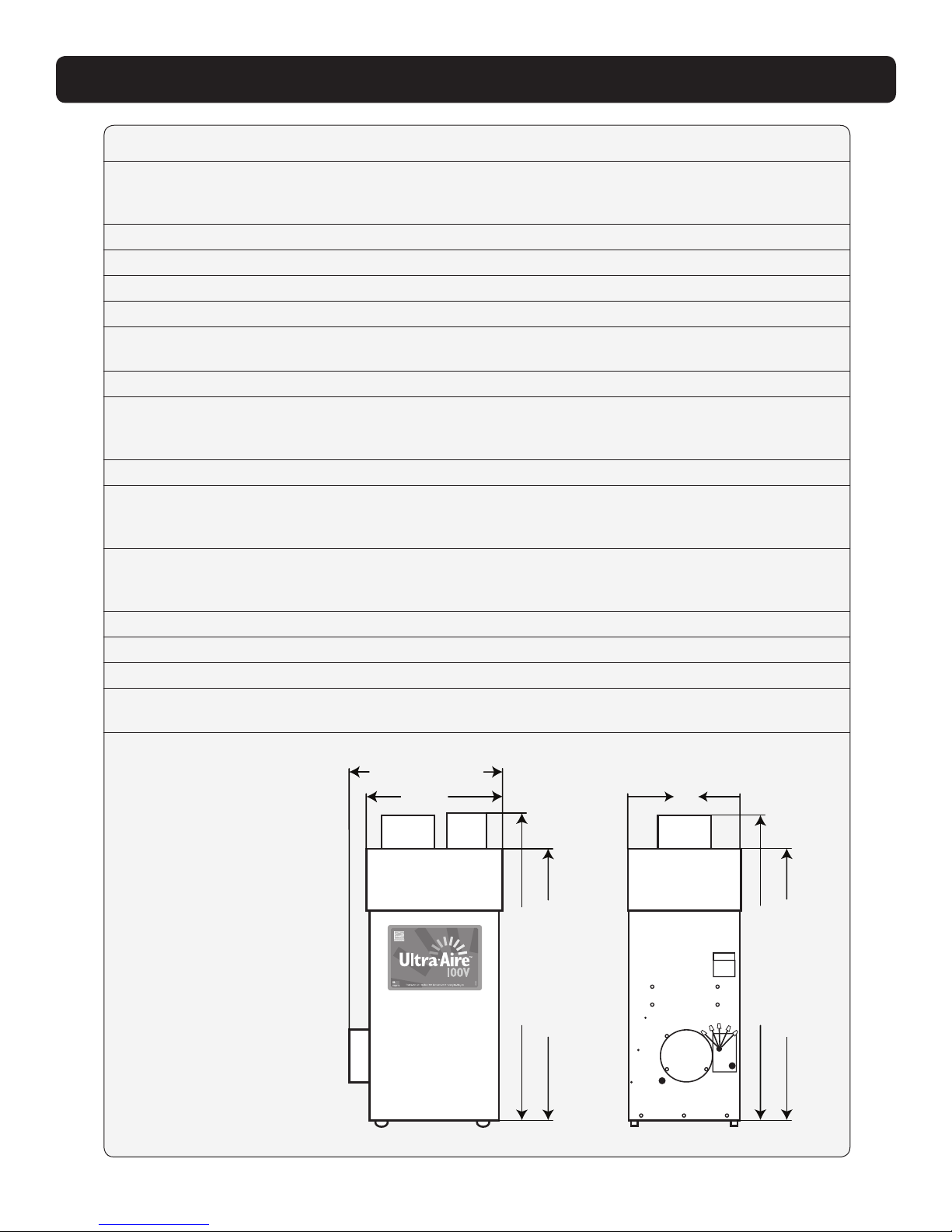
21”
With Collar Installed
8”
Diameter
Front View
Side View
19 3/4”
Without
Collar Installed
49”
With Collars Installed
Capacities and Performance
Part Number: 4029710
Blower: 255 CFM @ 0.0” WG
215 CFM @ 0.2” WG
170 CFM @ 0.4” WG
Power: 700 Watts @ 80°F and 60% RH
Supply Voltage: 115 VAC – 1phase – 60 Hz
Current Draw: 6.4 Amps
Energy Factor: 3.0 L/kWh
Operating Range: Between 56°F and 95°F Max
(Inlet Air Temperature)
Sized for: Up to 2,500 Sq. Ft. - Typical
Minimum Performance at: 80°F and 60% RH 70°F and 60% RH
Water Removal: 110 pints/day 90 pints/day
Efficiency: 5.3 Pints/kWh 6.0 Pints/kWh
Duct Connections: 6” Round Inlet; 8” Round Inlet; 8” Round Outlet
Air Filter: MERV-11, Standard Pleat
Efficiency: 65% ASHRAE Dust Spot
Size: 16” x 20” x 2”
Optional Air Filter: MERV-14, Embossed Pleat
(will need filter housing)
Efficiency: 95% ASHRAE Dust Spot
Size: 16” x 20” x 4”
Power Cord:9’, 115 VAC, Ground
Drain Hose: 6’ Direct Gravity Drain Hose (9/16” ID x 3/4” OD)
Refrigerant Type: R410A (Refer to manufacturers label for more
information)
Refrigerant Amount: 1 lb., 7 oz.
Dimensions:Unit With Collars Unit Without Collars Shipping
Width: 21” 21” 24”
Height: 49” 43” 49”
Length: 17” 17” 21”
Weight: 119 lbs. 120 lbs. 138 lbs.
43”
Without Collars Installed
49”
With Collars Installed
43”
Without Collars Installed
17”
Dimensions:
Unit With Collars
Width: 21"
Height: 49”
Length: 17”
Weight: 119 lbs.
Unit Without Collars
Width: 19 3/4”
Height: 43”
Length: 17”
Weight: 118 lbs.
Shipping
Width: 24”
Height: 49”
Length: 21”
Weight: 138 lbs.

5
www.Ultra-Aire.com | 1-800-533-7533 Ultra-Aire 100V Installation Instructions
OPTIONAL ACCESSORIES
4028539 DEH 3000 Control
4028407 DEH 3000R Control (with remote)
4021475 MERV 11 Filter (16”x20”x2”)
4027420 MERV 11 Filter, 4-Pack
4027424 MERV 11 Filter, 12-Pack
4024528 Bulk Carbon Granules
4022220 Pump Kit
4022489 MERV 14 Filter (16”x20”x4”)
4023484 Attic Insulation Kit
4023672 6” Motorized Damper
4026859 6” Flext Duct, 25’
4020128 6” Insulated Flex Duct, 25’
4020656 6” Inlet Hood
4023647 8” Gravity Damper
4020646 8” Butterfly Damper
4027415 8” Flex Duct, 25’
4020177 8” Insulated Flex Duct, 25’
Items Included in Box:
• Ultra-Aire 100V Dehumidifier
• Ultra-Aire 100V Installation Instructions

6Ultra-Aire 100V Installation Instructions www.Ultra-Aire.com | 1-800-533-7533
Important Precautions
• The device is designed to be installed indoors in a space that is protected from rain and flooding.
• Install the unit with enough space to access the front panel for maintenance and service.
• Avoid directing the discharge air at people. The dehumidifier should be used in the upright position.
• If used near a water source; be certain there is no chance the unit could fall into the water or get splashed and
that it is plugged into a dedicated circuit and Ground Fault Circuit Interrupter (GFCI) protected outlet.
• DO NOT use the dehumidifier as a bench or table.
• DO NOT place the dehumidifier directly on structural building members without vibration absorbers or unwanted
noise may result. Place the Ultra-Aire 100V on supports to raise the base of the unit.
• A drain pan MUST be placed under the dehumidifier if installed above a living area or above an area where
water leakage could cause damage.
Location Considerations
• Allow sufficient clearance to handle the unit’s overall dimensions as well as the necessary return and supply
ductwork to the unit.
• Allow sufficient clearance for filter removal and to prevent airflow obstruction.
• Electrical service access will require the removal of a side panel. Allow sufficient clearance on a side of the unit.
• Locate the dehumidifier in an area where the cord’s length (9') easily reaches a 115 VAC electrical outlet with a
minimum of a 15 Amp circuit capacity.
• Locate the dehumidifier in an area where field wiring the control (low voltage) to the unit will be possible.
• It is recommended that a backdraft damper be used in the discharge duct of the Ultra-Aire 100V, especially
when connecting to the supply ducting system. The backdraft damper prevents supply air from counter
flowing through the Ultra-Aire 100V
when it is not operating. The
dehumidifier’s location should be
chosen to allow installation of this
accessory if necessary.
• DO NOT hang the Ultra-Aire 100V
from its cabinet.
• Allow for proper routing and
drainage of needed drain pipes.
21”
Front View
49”
70°F and 60% RH
90 pints/day
6.0 Pints/kWh
Shipping
24”
49”
21”
138 lbs.
Minimum
Clearance
For Filter
Drain Hose
6” Fresh Air Intake (Optional)
8” Return Air Duct
8” Supply Air Duct
20”
Electrical Service
Access is through
the front panel
of dehumidifier
DEHUMIDIFIER SET UP

7
www.Ultra-Aire.com | 1-800-533-7533 Ultra-Aire 100V Installation Instructions
Front View
70°F and 60% RH
90 pints/day
6.0 Pints/kWh
Shipping
24”
49”
21”
138 lbs.
6” Fresh Air Ventilation Duct (Optional)
8” Return Air Inlet Duct
8” Supply Air Outlet Duct
ATTACHING DUCT COLLARS
Fresh Air Ventilation Duct
Fresh air ventilation is optional. A 6" diameter duct is attached to the unit. The 6" duct should be capped if
fresh air is not desired. If setting up the unit to provide fresh air ventilation, see page 17.
Return Air Inlet
An 8" diameter duct collar is attached to the unit.
Supply Air Outlet
An 8” diameter duct collar is attached to the unit.

8Ultra-Aire 100V Installation Instructions www.Ultra-Aire.com | 1-800-533-7533
The Ultra-Aire 100V plugs into a common grounded 115 VAC outlet. The device draws 5.9 Amps at 80°F
and 60% RH. Locate the dehumidifier in an area where the cord’s length (9') easily reaches a 115 VAC
electrical outlet with a minimum of 15 Amp circuit capacity. If used in an area that may become wet, a GFCI
protected circuit is recommended. Consult local electrical codes for further information.
Ultra-Aire offers a variety of control devices for use with the Ultra-Aire 100V. The control is to be located
remotely from the dehumidifier and placed in the space to be conditioned. A low voltage (24 Volt) control MUST
be used with the Ultra-Aire 100V and MUST be connected with low voltage (18-22 gauge) thermostat wire.
ELECTRICAL REQUIREMENTS
CAUTION!
DO NOT ALLOW THE YELLOW LEAD TO CONTACT THE RED OR WHITE LEAD ON THE
ULTRA-AIRE 100V OR DAMAGE TO THE TRANSFORMER WILL RESULT.
Electrical Precautions
• Do not install the control where it may not accurately sense the relative humidity such as near HVAC
supply registers, near exterior doors, on an outside wall, near a window, or near a water source.
• The control wires leaving the Ultra-Aire 100V and the control are numbered and color-coded to
prevent confusion.
• Be sure to consult the
electrical schematic in the
CONTROLS Section
(page 19) of this manual or
inside the access panel of
the Ultra-Aire 100V
before making control
connections.
WARNING!
THE REMOTE CONTROLS OF THE ULTRA-AIRE 100V ARE POWERED BY A LOW VOLTAGE CIRCUIT
(24 VAC) AND MUST NEVER CONTACT OR BE CONNECTED TO A HIGH VOLTAGE CIRCUIT.
CAUTION!
SOME OF THE CONTROL WIRES LEAVING THE ULTRA-AIRE 100V MAY NOT BE USED WITH
CERTAIN CONTROLS AND SHOULD BE LEFT UNCONNECTED WITH WIRE NUTS TAPED ONTO
THE STRIPPED ENDS FOR SAFETY.
Wiring Diagrams

9
www.Ultra-Aire.com | 1-800-533-7533 Ultra-Aire 100V Installation Instructions
The Ultra-Aire 100V generates condensate.
Place a secondary drain pan under the dehumidifier if it is suspended above a finished area or above an
area where water leakage could cause damage.
Condensate drains by gravity via the clear hose extending from the unit. Route the hose to a floor drain. Use
care to keep the hose as flat to the floor as possible; excessive humps will prevent proper drainage. We do
not call for a trap since there is an internal trap with this unit. If the Ultra-Aire 100V is located too far from a
floor drain for the attached hose to reach, inexpensive 1⁄2” PVC pipe can be used to extend it. It is commonly
available in 10’ lengths from building supply, plumbing and hardware stores. It will slide tightly inside the end
of the drain hose. If more than one length of pipe is required, they can be joined with a short piece cut from the
end of the drain hose.
An optional condensate pump kit is available for use with the Ultra-Aire 100V and may be installed if lift is
required to dispose of condensate. Condensate is automatically pumped to a remote location when the
water level in the pump’s reservoir rises to close the float switch.
The pump also contains a safety float
switch. The white leads from this
switch extend from beneath the pump
cover. This switch should be installed
in series with the field wire that
connects to the common lead from
the Ultra-Aire 100V to the control panel.
If the pump fails, this switch opens
the common control circuit and stops
water production before the reservoir
overflows. Contact a qualified electrician
to install the safety float switch to the
Ultra-Aire 100V dehumidifier.
Note: An optional condensate pump
kit can be purchased through your
dealer or online.
Supply
Air
Outlet
Side View
Capacities and Performance
Part Number: 4029710
Blower: 255 CFM @ 0.0” WG
215 CFM @ 0.2” WG
170 CFM @ 0.4” WG
Power: 700 Watts @ 80°F and 60% RH
Supply Voltage: 115 VAC – 1phase – 60 Hz
Current Draw: 6.4 Amps
Energy Factor: 3.0 L/kWh
Operating Range: Between 56°F and 95°F Max
(Inlet Air Temperature)
Sized for: Up to 2,500 Sq. Ft. - Typical
Minimum Performance at: 80°F and 60% RH 70°F and 60% RH
Water Removal: 110 pints/day 90 pints/day
Efficiency: 5.3 Pints/kWh 6.0 Pints/kWh
Duct Connections: 6” Round Inlet; 8” Round Inlet; 8” Round Outlet
Air Filter: MERV-11, Standard Pleat
Efficiency: 65% ASHRAE Dust Spot
Size: 16” x 20” x 2”
Optional Air Filter: MERV-14, Embossed Pleat
(will need filter housing)
Efficiency: 95% ASHRAE Dust Spot
Size: 16” x 20” x 4”
Power Cord:9’, 115 VAC, Ground
Drain Hose: 6’ Direct Gravity Drain Hose (9/16” ID x 3/4” OD)
Refrigerant Type: R410A (Refer to manufacturers label for more
information)
Refrigerant Amount: 1 lb., 7 oz.
Dimensions:Unit With Collars Unit Without Collars Shipping
Width: 21” 21” 24”
Height: 49” 43” 49”
Length: 17” 17” 21”
Weight: 119 lbs. 120 lbs. 138 lbs.
Drain Hose Drain Pan
DRAIN INSTALLATION
Drain Installation

10 Ultra-Aire 100V Installation Instructions www.Ultra-Aire.com | 1-800-533-7533
The recommended installation creates a separate return for the Ultra-Aire 100V in a central area of the
structure. Duct the supply of the unit to the air supply of the existing HVAC system. Connect an insulated
duct from outside to the 6" collar of the Ultra-Aire 100V to provide fresh make-up air.
DUCTING TO HVAC SYSTEMS
CAUTION!
DO NOT CONNECT WITH A STATIC PRESSURE GREATER THAN OR EQUAL TO +0.5 WG.
CONTACT TECHNICAL SUPPORT AT 1-800-533-7533 FOR ADDITIONAL DETAILS.
Ducting Considerations:
• All flexible ducting connected to the Ultra-Aire 100V should be UL listed.
• A short piece of flexible ducting on all Ultra-Aire 100V duct connections is recommended to reduce noise
and vibration transmitted to rigid ductwork in the structure.
• Use a minimum 8" diameter round or equivalent rectangular duct for total duct lengths of up to 25'. Use a
minimum 10" diameter round or equivalent rectangular duct for longer lengths.
• Grills or diffusers on the duct ends must not excessively restrict airflow.
• A length of 10" or more of insulated flex duct or any other vibration isolating material on the outlet of the
Ultra-Aire 100V will reduce air noise from the blower.
• Effective dehumidification may require that ducting be branched to isolated, stagnant air flow areas.
When ducting to two or three areas, use 8" or larger diameter branch ducting. When ducting to four or
more areas, use 6" or larger diameter branch ducting. Provisions must be made to provide airflow from
supply locations to the central return location. Proper air distribution is important to ensure even humidity
control and heat distribution throughout the structure.
• DO NOT locate the return in a bathroom or a kitchen.

11
www.Ultra-Aire.com | 1-800-533-7533 Ultra-Aire 100V Installation Instructions
HVAC
Supply
Ultra-Aire
Supply
HVAC
Return
Ultra-Aire
Return
Fresh Air Intake
(Optional)
Backdraft
Damper
Motorized
Damper
Backdraft
Damper
Dry Air to
Basement
Manual
Damper
Basement / Crawlspace Intall
Air Handler Supply
Ultra-Aire Supply
Fresh Air Intake
(Optional)
Indoor
A
ir Return
Motorized
Damper
Recommended HVAC System Installations
DUCTING TO HVAC SYSTEMS
• Install a dedicated 8" air return for the Ultra-Aire 100V from a central area of the structure.
• Install an insulated duct from outside to the 6" collar of the Ultra-Aire 100V to provide fresh air
ventilation (optional).
• Duct the supply of the Ultra-Aire 100V to a 8” x 8” x 8” tee damper that is 20 percent open to the
basement/crawlspace. Duct the other side of the tee to the air supply of the existing HVAC system
with a backdraft damper.
• If the existing system has multiple
returns, instead of installing a
dedicated return to the Ultra-Aire
100V, it is possible to select one to
disconnect from the existing HVAC
system and use it for the dedicated
Ultra-Aire 100V return. Select a return
from a central location in the house
that is always open to the rest of the
structure. DO NOT use a return from
a room where doors are kept closed.
• DO NOT locate return in a bathroom
or kitchen.
• Control should be located remotely from the dehumidifier and placed in a central location.
Basement Installation - Dedicated Ultra-Aire Return to HVAC Supply
• Locate the dehumidifier under or next to the
HVAC system as space allows. A passive vent or
louver door is required to allow air to be pulled in
from the living space.
• No inlet duct is required. Air is pulled through the
passive vent or louver door from the living space.
Where outlet space is restricted, the outlet duct
collar is optional.
• Install an insulated duct from outside to the 6"
collar of the Ultra-Aire 100V to provide fresh air
ventilation (optional).
• Duct the supply of the Ultra-Aire 100V to the
supply of the existing HVAC system with a
backdraft damper.
• Control should be located remotely from the
dehumidifier and placed in a central location.
WARNING!
WHEN INSTALLING THE DEHUMIDIFIER AS PART OF A COMBUSTION TYPE HVAC SYSTEM (GAS,
OIL, PROPANE, ETC.), FOLLOW ALL LOCAL AND NATIONAL BUILDING AND SAFETY CODES.
Closet Installation - Central Return to HVAC Supply

12 Ultra-Aire 100V Installation Instructions www.Ultra-Aire.com | 1-800-533-7533
Air Handler
HVAC Return
HVAC Return to A/C Return
HVAC Supply
Fresh Air
Intake
(Optional)
Motorized
Damper
Ultra-Aire Supply
Ultra-Aire Supply
Air Handler
HVAC Return
HVAC Return to A/C Supply
HVAC Supply Fresh Air
Intake
(Optional)
Backdraft Damper
Motorized
Damper
Optional Check Damper
(no HVAC fan needed)
Air Handler
HVAC Return
Dedicated Ultra-Aire 100V Return to A/C Supply
HVAC Supply Fresh Air
Intake
(Optional)
Indoor
Air Return Motorized
Damper
Ultra-Aire Supply
DUCTING TO HVAC SYSTEMS
Alternative HVAC System Installations
If the Recommended Dedicated Ultra-Aire Return to HVAC Supply Installation is not possible, there are several
alternative installation options available.
• DO NOT locate return in a bathroom or kitchen.
• Control should be located remotely from the dehumidifier and placed in a central location.
• For basement installations, an optional tee can be installed on the Ultra-Aire Supply.
HVAC Return to HVAC Supply
Check Damper should be in place between
the Return and Supply connections of the
dehumidifier.
If Check Damper is not in place, the
HVAC fan must turn on when the
dehumidifier is in operation.
Dedicated Ultra-Aire Return to HVAC Return
Create a separate return for the Ultra-Aire 100V in
a central area of the building.
Installing the supply air from the Ultra-Aire 100V to
the return of the HVAC system requires the HVAC
fan to run when the Ultra-Aire 100V is operating.
HVAC Return to HVAC Return
Check Damper should be in place between
the Return and Supply connections of the
dehumidifier.
Installing the supply air from the Ultra-Aire
100V to the return of the HVAC system
requires the HVAC fan to run when the
Ultra-Aire 100V is operating.
Ultra-Aire Supply
Air Handler
HVAC Return
Dedicated Ultra-Aire 100V Return to A/C Supply
HVAC Supply
Fresh Air Intake
(Optional)
Indoor
Air Return
Backdraft Damper
Motorized Damper
Dedicated Ultra-Aire Return to HVAC Supply
Create a separate return for the Ultra-Aire
100V in a central area of the building.
Duct the supply of the Ultra-Aire 100V to the
air supply of the HVAC system with a back
draft damper.
An attic insulation kit is needed for the
attic installation.

13
www.Ultra-Aire.com | 1-800-533-7533 Ultra-Aire 100V Installation Instructions
DUCTING TO HVAC SYSTEMS
Alternative Closet Installations
HVAC
Supply
Ultra-Aire
Supply
HVAC
Return
Ultra-Aire
Return
Fresh Air Intake
(Optional)
Motorized
Damper
Closet Installation - Central Return
to HVAC Return
Duct the supply of the Ultra-Aire 100V to the
return side of the existing HVAC system.
The HVAC fan must run when the dehumidifier
is running.
HVAC
Supply
Ultra-Aire
Supply
HVAC
Return
Ultra-Aire
Return
Fresh Air Intake
(Optional)
Motorized
Damper
Closet Installation - No Duct, Central Return
to HVAC Return
Attach outlet duct so air is not discharged
into wall or other obstruction. The HVAC
system will naturally pull dehumidified air
from the closet and distribute throughout
the structure.
If the Recommended Closet Installation is not possible, there are several alternative installation options available.
• No inlet duct is required. Air is pulled through the passive vent or louver door from the living space.
• Install an insulated duct from outside to the 6" collar of the Ultra-Aire 100V to provide fresh air ventilation
(optional).
• Control should be located remotely from the dehumidifier and placed in a central location.

14 Ultra-Aire 100V Installation Instructions www.Ultra-Aire.com | 1-800-533-7533
DUCTING TO HVAC SYSTEMS
The Ultra-Aire 100V can be installed on multiple HVAC systems. Dehumidified air will be provided to both
HVAC systems for distribution throughout the structure.
• Backdraft dampers are required in the supply ducts.
• DO NOT locate the return in a bathroom or kitchen.
• One control will service both HVAC zones. Control should be located remotely from the dehumidifiers and
placed in a central location.
• HVAC systems should be in close proximity for optimal air flow.
• For multiple systems, contact Technical Support at 1-800-533-7533.
Recommended Multiple HVAC Systems Installation
HVAC
Supply
Ultra-Aire
Supply
Second Air Handler
Dedicated Ultra-Aire 90 Return to multi systems A/C Supply
HVAC Return
Backdraft
Damper
First Air HandlerHVAC Return
HVAC
Supply
Backdraft
Damper
Indoor
Air Return
Fresh Air
Intake
(Optional)
Motorized
Damper
Dedicated Ultra-Aire Return to Multiple HVAC Systems
CAUTION!
DO NOT CONNECT WITH A STATIC PRESSURE GREATER THAN OR EQUAL TO +0.5 WG.
CONTACT TECHNICAL SUPPORT AT 1-800-533-7533 FOR ADDITIONAL DETAILS.

15
www.Ultra-Aire.com | 1-800-533-7533 Ultra-Aire 100V Installation Instructions
DUCTING TO HVAC SYSTEMS
When installing the Ultra-Aire 100V in a structure that does not have a forced air HVAC system, a single
return for the Ultra Aire 100V should be installed in a central location.
Install an insulated duct from outside to the 6" collar of the Ultra-Aire 100V to provide fresh air
ventilation (optional).
The supply of the Ultra-Aire 100V should be ducted to remote areas of the structure such as bedrooms, living
room, den, etc. Be sure to utilize multiple rooms to allow air inside the structure to properly circulate. Proper
air distribution is important to ensure even humidity control and heat distribution throughout the structure.
A 6" diameter duct is recommended for branches to bedrooms. An 8" diameter duct is recommended for
branches to larger areas.
• DO NOT locate the return in a bathroom or kitchen.
• DO NOT locate the supply in rooms where doors may be closed.
• Control should be located remotely from the dehumidifier and placed in a central location.
Indoor
Air Return
Fresh Air
Intake
(Optional)
Motorized
Damper
Ultra-Aire
Supply
No Existing Ductwork Installation

16 Ultra-Aire 100V Installation Instructions www.Ultra-Aire.com | 1-800-533-7533
Fresh air ventilation is optional.
Fresh air may be brought into the structure by connecting an insulated duct from outside the structure to
the 6" inlet of the Ultra-Aire 100V. A ventilation control is needed to program the time and frequency that
the unit introduces outside air. The time and frequency of ventilation should be based on the size and
occupancy of the residence.
• The fresh air ventilation duct should be connected to the 6" round collar on the front of the Ultra-Aire 100V.
• An insulated 6" diameter duct provides up to 75 CFM of outside air.
• If a motorized damper is not being used, fresh air is controlled by the manual damper in the 6” collar of the
Ultra-Aire 100V.
• Performance of the Ultra-Aire 100V can be impacted by inside and outside air conditions.
• When a 6" motorized damper is used, a digital control is required.
• It may be necessary to use 8" duct work if additional fresh air is required.
• In cold climates or at times when the dew point is low, ventilation can be used to dehumidify the
structure, making the Ultra-Aire 100V capable of year-round drying.
FRESH AIR VENTILATION
70°F and 60% RH
90 pints/day
6.0 Pints/kWh
Shipping
24”
49”
21”
138 lbs.
6” Fresh Air Ventilation Duct (Optional)
8” Return Air Inlet Duct
8” Supply Air Outlet Duct
Front View
Hot Climate
Outdoor Air
90°F, 65%RH
Indoor Air
70°F, 50%RH
Outlet Air
75°F, 65%RH
Side View
Hot Climate
Front View
Cold Climate
Outdoor Air
30°F, 65%RH
Indoor Air
70°F, 50%RH
Outlet Air
59°F, 51%RH
Mixed
Air 75°F
65%RH
59°F
51%RH
59°F
51%RH
75°F
65%RH
Mixed
Air
Fresh Air Ventilation With Dehumidier O and Fan Only Operation
Outside air mixes with the dehumidifier’s
return air before being supplied to the
home. Outside temperature, inside
temperature and relative humidity
will impact the combined outlet
air conditions.
Note: Temperature and relative
humidity may vary depending on
duct distribution scheme.

17
www.Ultra-Aire.com | 1-800-533-7533 Ultra-Aire 100V Installation Instructions
Option 1: Calculating Airflow Requirement Using ASHRAE 62.2-2010 Airflow Equation
ASHRAE Airflow in CFM = [House Area in Sq.Ft. x 0.01] + [(Number of Bedrooms +1) x 7.5]
NOTE: Use ‘Number of Bedrooms + 1’ or ‘Number of Occupants’, whichever is larger.
Example 1: Number of Bedrooms + 1
2500 square foot house with 3 bedrooms, 4 occupants = [2500 X 0.01] + [(3+1) X 7.5] = 55 CFM
Example 2: Number of Occupants
2500 square foot house with 3 bedrooms, 5 occupants = [2500 X 0.01] + [5 X 7.5] = 62.5 CFM
Record the required CFM ____________
FRESH AIR VENTILATION
Determine Ventilation Requirements
The MINIMUM ventilation requirement is calculated using ASHRAE 62.2-2010. Use one or both of the options
below to determine your ventilation requirement. Follow all local and national building and safety codes.
Table 4.1 from ASHRAE 62.2-2010
Floor Area
(ft2)
< 1500 ft2
1501 - 3000
3001 - 4500
4501 - 6000
6001 - 7500
> 7500 ft2
0-1
30
45
60
75
98
105
2-3
45
60
75
98
105
120
4-5
60
75
98
105
120
135
6-7
75
98
105
120
135
150
>7
98
105
120
135
150
165
Number of Bedrooms
Option 2: Calculating Airflow Requirement Using Table 4.1 from ASHRAE 62.2-2010
See chart below to find the calculated airflow values to the nearest 5 CFM.
Record the required CFM ____________
Ventilation Air Requirements, CFM

18 Ultra-Aire 100V Installation Instructions www.Ultra-Aire.com | 1-800-533-7533
A control must be used with the Ultra-Aire 100V. Ultra-Aire offers the DEH 3000 proprietary control. The
DEH 3000 allows homeowners to monitor and control relative humidity and proper ventilation levels in their
home. This control is also available with a remote sensing option.
Note: The DEH 3000 is sold seperately and can be purchased through your local dealer or online. Other
thermostats are compatible with the Ultra-Aire 100V.
CONTROLS
CAUTION!
DO NOT ALLOW THE YELLOW LEAD FROM THE ULTRA-AIRE 100V TO CONTACT THE RED
LEAD OR THE WHITE LEAD FROM THE ULTRA-AIRE 100V OR DAMAGE TO THE TRANSFORMERS
WILL RESULT.
DO NOT CONNECT THE WHITE WIRE TO THE CONTROL IF THE OPTIONAL DAMPER IS NOT
USED OR DAMAGE TO THE TRANSFORMER WILL RESULT.
• Central Fan Integration – Operates HVAC
fan with dehumidifier operation.
• A/C Sensor – Automatically activates or
deactivates the dehumidifier when the air
conditioner runs.
• High Temperature Cut-Out – Disables
dehumidifier operations if household
temperature reaches the cut-out setpoint.
• Dry-Out Cycle Timer – Automatic fan
cycling to ensure dry and clean coils.
• Auto Reboot – Resumes operation with
prior settings in the event of power failure.
Ultra-Aire DEH 3000 Digital Control
Wiring Controls
See DEH 3000 manual for detailed instructions.

19
www.Ultra-Aire.com | 1-800-533-7533 Ultra-Aire 100V Installation Instructions
CONTROLS
A low voltage control must be used with the Ultra-Aire 100V.
Basic Control Wiring
Control
Dehumidifier
Yellow
Yellow
Blue
Blue
Low Voltage
Wiring
Green (or brown) Fan control
Blue Dehumidication (fan and compressor) control
Red 24 VAC power transformer neutral side (common with white)
White 24 VAC power transformer neutral side (common with red)
Yellow Transformer high side
Five Color Coded Wires Control Operation
Unit ON & Fan ON Make contact between yellow and blue wires
Unit OFF / Fan On Make contact between yellow and green (or brown) wires
Power HVAC Accessory Connect the accessory to the white (or red) wire and the yellow wire
Between the red/white lead and the yellow lead is a 40VA transformer. This low voltage power source
powers the relay coils which control the fan and compressors. This 24 VAC transformer can also be
used to power HVAC accessories external to the dehumidifier.

20 Ultra-Aire 100V Installation Instructions www.Ultra-Aire.com | 1-800-533-7533
The Ultra-Aire 100V is equipped with a MERV-11 filter. An optional MERV-14 filter and filter housing is
available at www.UltraAireFilters.com. The MERV-11 filter should be checked and replaced every three to six
months. If the MERV 14 filter is used, the MERV 11 should act as a pre-filter and sit on top of the MERV 14
filter. Replacing the MERV 11 filter every three to six months extends the life of the MERV 14. The MERV 14
filter should be replaced every two to three years if a MERV 11 is used as a pre-filter and replaced every three
to six months. Operating the unit with a dirty filter will reduce dehumidifier capacity and efficiency.
DO NOT operate the unit without the recommended filter. Filter non-compliance voids the product warranty.
AIR FILTRATION
Changing the Filter
For greatest filtration and efficiency of the Ultra-Aire 100V, it is recommended the air filter be replaced
every three to six months with a MERV-11 filter.
Step 1: Filter access panels are available on either side of the filter housing at the top of the dehumidifier.
Pull straight up on the filter access panel until the bolt heads near the bottom of the panel are centered
in the larger opening of the keyhole slots, then pull up and out to release the tab at the top of the filter
access panel.
Step 2: Remove the used filter(s) from
the housing. Insert the new filter by gently
pushing it straight into the housing. Make
sure the air flow arrows on the filter are
pointing down into the unit.
Step 3: Reattach the filter access panel by inserting the tab at the top of the panel into the slot of the
filter housing. Once in place, push straight down and in, ensuring the bolt heads are lined up with the
keyhole slots in the filter access panel.
CAUTION!
MAKE SURE UNIT IS OFF BEFORE CHANGING THE FILTER.
Front View
70°F and 60% RH
90 pints/day
6.0 Pints/kWh
Shipping
24”
49”
21”
138 lbs.
6” Fresh Air Intake (Optional)
8” Return Air Duct
8” Supply Air Duct
Filter
Access
Panel
Tab
Filter
Housing
Filter
Access
Panel
Tab
Front View
70°F and 60% RH
90 pints/day
6.0 Pints/kWh
Shipping
24”
49”
21”
138 lbs.
Minimum
Clearance
For Filter
6” Fresh Air Intake (Optional)
8” Return Air Duct
8” Supply Air Duct
20”
Filter Access
(Either Side)
Side View
Filter
Access
Panel
Side View
Filter
Access
Panel
Bolt Heads and
Keyhole slots
Bolt Heads and
Keyhole slots
70°F and 60% RH
90 pints/day
6.0 Pints/kWh
Shipping
24”
49”
21”
138 lbs.
6” Fresh Air Intake (Optional)
8” Return Air Duct
8” Supply Air Duct
Pull
Out Filter Housing
Filter
Push
In Filter Housing
Filter
70°F and 60% RH
90 pints/day
6.0 Pints/kWh
Shipping
24”
49”
21”
138 lbs.
6” Fresh Air Intake (Optional)
8” Return Air Duct
8” Supply Air Duct
Pull
Out Filter Housing
Filter
Push
In Filter Housing
Filter
Front View
Front View
70°F and 60% RH
90 pints/day
6.0 Pints/kWh
Shipping
24”
49”
21”
138 lbs.
6” Fresh Air Intake (Optional)
8” Return Air Duct
8” Supply Air Duct
Filter
Access
Panel
Tab
Filter
Housing
Filter
Access
Panel
Tab
Front View
Front View
70°F and 60% RH
90 pints/day
6.0 Pints/kWh
Shipping
24”
49”
21”
138 lbs.
Minimum
Clearance
For Filter
6” Fresh Air Intake (Optional)
8” Return Air Duct
8” Supply Air Duct
20”
Filter Access
(Either Side)
Side View
Filter
Access
Panel
Side View
Filter
Access
Panel
Bolt Heads and
Keyhole slots
Bolt Heads and
Keyhole slots
Side
View
Side
View
Front View
Table of contents
Other Ultra-Aire Dehumidifier manuals