Ultra-Aire SD12 User manual

INSTALLER’S & OWNER’S MANUAL
HVAC INSTALLER: PLEASE LEAVE MANUAL FOR HOMEOWNER
Dehumidification
The Ultra-Aire SD12 is a split system dehumidifier that removes over
180 pints of water a day while adding no sensible heat load to the
living space. The dehumidifying unit is located inside the house and
the condensing coil is located outside. The two-piece design allows
the sensible heat load generated from dehumidifying the house to be
released in the outside condensing unit, thus eliminating additional
cooling load and reducing air conditioner run time.
Sensible Cooling
The Ultra-Aire SD12 provides approximately 1/3 ton sensible
cooling to the living space, allowing for first stage cooling and
moisture removal. The HVAC system can be used as a second stage
and be thermostatically set to a higher temperature to provide
additional cooling if needed. By eliminating the HVAC system’s need
to control latent load, the Ultra-Aire SD12 allows the system to work
more efficiently.
Fresh Air Ventilation
Optional fresh outdoor air may be ducted to the unit via a six inch
round duct. This provides fresh air to dilute pollutants and replenish
oxygen content in the building. The amount of fresh air ventilation
can be regulated by a variety of dampers and controls.
Air Filtration
The Ultra-Aire SD12 includes air filtration to improve indoor air
quality. A MERV-11 media filter is standard. An optional external
filter box with a MERV-14 deep pleated 95% media filter is
available for optimum air filtration and to reduce potentially
harmful airborne particles.
© 2012 Therma-Stor LLC •Manual P/N TS-712
P/N 4033170 • Serial No.________________________ Install Date:___________
Sold by:
PATENT PENDING:
D570,988

Ultra-Aire SD12 Installer’s & Owner’s Manual
2
TABLE OF CONTENTS
Safety Precautions ...................................................... 3
1. Intended Application for the Ultra-Aire SD12......... 3
2. Specifications .......................................................... 3
2.1 Dehumidifier and Condensing
Unit Specifications........................................ 3
2.2 Dehumidifier Specifications ........................... 3
2.3 Condensing Unit Specifications...................... 4
3. Installation............................................................... 4
3.1 Location ........................................................ 4
3.1A Dehumidifier Location........................... 4
3.1B Condensing Unit Location ..................... 4
3.2 Electrical Requirements................................. 5
3.2A Dehumidifier Electrical Power
Connections.......................................... 5
3.2B Remote Control Electrical
Connection ........................................... 6
3.2C Condensing Unit Electrical Power
Connection ........................................... 6
3.2D Field Wiring the Condensing Unit .......... 6
3.3 Line Set Installation ....................................... 7
3.4 Brazing the Line Set ...................................... 8
3.5 Leak Test Line Set and Dehumidifier ............. 9
3.6 Evacuating the Line Set and the
Dehumidifier................................................ 10
3.7 Charging the System ................................... 10
3.8 Condensate Water Removal......................... 10
3.9 Ducting........................................................ 11
3.9A Installing Duct Collars......................... 11
3.9B Ducting for Dehumidification .............. 11
3.9C Ducting for Fresh Air........................... 12
3.9D Installation in a Basement or
Crawlspace with an Existing
Forced Air HVAC System..................... 12
3.9E Installation in an Attic
with an Existing Forced
Air HVAC System................................. 13
3.9F Installation in a Structure
with Two Forced Air
HVAC Systems .................................... 13
3.9G Installation in a Structure
with No Existing Forced
Air HVAC System ................................ 13
3.10 Quiet Installation........................................ 13
3.11 System Start Up ........................................ 13
4. Controls.............................................................13-14
5. Optional Dehumidifier &
Ventilation System Controller................................ 15
6. Maintenance .......................................................... 16
6.1 Standard Air Filter........................................ 16
6.2 High Efficiency Air Filter – MERV 14............. 16
6.3 Impeller Fan ................................................ 16
6.4 Optional Fresh Air Return............................. 16
6.5 Condensing Unit Maintenance ..................... 16
7. Service ................................................................... 16
7.1 Warranty ..................................................... 16
7.2 Technical Description .................................. 16
7.3 Troubleshooting........................................... 17
7.4 Refrigerant Charging ................................... 18
7.5 Dehumidifier Impeller Fan Replacement ...... 18
7.6 Condensing Unit Fan/Blade Replacement..... 18
7.7 Compressor/Capacitor Replacement............ 18
7.7A Checking Compressor Motor Circuits .. 18
7.7B Replacing a Burned Out Compressor .. 19
7.7C Replacing a Compressor,
Nonburn Out....................................... 19
7.8 Remote Controls........................................... 19
7.8A Humidity Control................................. 19
7.8B Programmable Ventilation Timer –
DEH3000/3000R................................. 19
7.9 Defrost Thermostat ...................................... 20
7.10 Electric Ventilation Damper ........................ 20
7.11 Condensate Pump Kit................................. 20
Service Parts List: Dehumidifier ............................... 21
Service Parts List: Condensing Unit.......................... 21
Optional Parts List ..................................................... 22
Door and Collar Assembly......................................... 22
Warranty .................................................................... 23

1. Intended Application for the Ultra-Aire SD12
For the ideal installation, draw air from the central part of the home
and return it to isolated areas of the home like the bedrooms, den,
utility room, or family room. The ductwork of the existing heating or
cooling system can be used to supply air to the home.
2. Specifications
2.1 Dehumidifier and Condensing Unit Specifications
Part Number: 4033170
Shipped Together on Pallet:
Pallet Dimensions
Width: 42”
Height: 32”
Depth: 42”
Weight: 220 lbs
2.2 Dehumidifier Specifications
Part Number: 4033175
Blower: 406 CFM @ 0.0” WG
374 CFM @ 0.2” WG
348 CFM @ 0.4” WG
Power: 160 Watts @ 80°F and 60% RH
Supply Voltage: 115 VAC – 1 Phase – 60 Hz.
Current Draw: 1.4 Amps
Energy Factor: 3.1 L/kWh
Operating Range: 56°F Min, 95°F Max (Inlet Air
Temperature)
Sized for: 4,000 Square Foot Typical
Minimum Performance at 80°F and 60% RH
Water Removal: 184 Pints/Day
Sensible Cooling: 4,300 BTUs/Hour
Efficiency: 6.6 Pints/kWh
Duct Connections:
6” Round Inlet; 10” Round Inlet; 10” Oval Outlet
Air Filter: MERV-11, Standard Pleat
Efficiency: 65% ASHRAE Dust Spot
Size: 16” x 20” x 2”
Optional Air Filter: MERV-14, Embossed Pleat
(will need filter housing)
Efficiency: 95% ASHRAE Dust Spot
Size: 20” x 24” x 4”
Power Cord: 10’, 115 VAC, Ground
Drain Connection: 3/4” Threaded Female NPT
Refrigerant Type: R410A (Refer to manufacturers label for
more information)
Refrigerant Amount: 15 oz.
3Ultra-Aire SD12 Installer’s & Owner’s Manual
SAFETY PRECAUTIONS
FOR HVAC INSTALLER ONLY
ULTRA-AIRE SD12 Dehumidifier Installation Instructions
Safety Precautions
Read the installation, operation and maintenance instructions care-
fully before installing and operating this device. Proper adherence to
these instructions is essential to obtain maximum benefit from your
Ultra-Aire SD12 indoor air quality system.
WARNING! IMPROPER INSTALLATION,
ADJUSTMENT, ALTERATION, SERVICE OR MAINTAINCE CAN CAUSE
PERSONAL INJURY, LOSS OF LIFE, OR DAMAGE TO PROPERTY.
INSTALLATION AND SERVICE MUST BE PERFORMED BY A
LICENSED PROFESSIONAL INSTALLER (OR EQUIVALENT) OR A
SERVICE AGENCY.
IMPORTANT! THE CLEAN AIR ACT OF 1990 BANS
THE INTENTIONAL VENTING OF REFRIGERANT (CFCs, HCFCs, AND
HFCs) AS OF JULY 1, 1992. APPROVED METHODS OF RECOVERY,
RECYCLING OR RECLAIMING MUST BE FOLLOWED. FINES AND/OR
INCARCERATION MAY BE LEVIED FOR NONCOMPLIANCE.
READ AND SAVE THESE INSTRUCTIONS
• The Ultra-Aire SD12 Dehumidifier is designed to be installed IN-
DOORS IN A SPACE THAT IS PROTECTED FROM RAIN AND FLOODING.
• Install the Dehumidifier with space to access the back or side
panels for maintenance and service. DO NOT INSTALL UNITS WITH
THE SERVICE PANELS INACCESSIBLE.
• Install the Condensing unit with space to access the top and side
panels for maintenance and service. DO NOT INSTALL UNITS WITH
THE SERVICE PANELS INACCESSIBLE.
• Avoid directing the discharge air at people, or over the water in
pool areas.
• If used near a pool or spa; be certain there is NO chance the
dehumidifier or condensing unit could fall into the water, be splashed
and that it is connected to a GFI GROUND FAULT INTERRUPT OUTLET
OR CIRCUIT.
• DO NOT use the dehumidifier or condensing unit as a bench or
table.
• DO NOT place the dehumidifier directly on structural members.
Provide vibration isolation in order to minimize operational vibration
and/or noise.
• A drain pan MUST be placed under the dehumidifier if installed
above a living area or above an area where water leakage could
cause damage.

Ultra-Aire SD12 Installer’s & Owner’s Manual
4
FOR HVAC INSTALLER ONLY
Dimensions:
Unit With Collars Unit Without Collars Shipping
Width: 20 1/4” 20 1/4” 35”
Height: 21 3/4” 21 3/4” 44”
Length: 41 1/2” 37 3/4” 44”
Weight: 110 lbs. 109 lbs. 225 lbs.
2.3 Condensing Unit Specifications
Part Number: 4033192
Power: 1080 Watts @ 80˚F and 60% RH
Supply Voltage: 110-120 volt – 1phase – 60 Hz
Current Draw: 9.7 AMPS
Min. Circuit Ampacity: 20 AMPS
Max. Fuse/Breaker Size: 20 AMPS
Refrigerant: R410a
Operating Temp.: 40°F Min., 115°F Max.
Dimensions Unit
Width: 10”
Height: 25.5”
Depth: 33”
Weight: 75 lbs
3. Installation
3.1 Location
3.1A Dehumidifier Location
The Ultra-Aire SD12 Dehumidifier can be installed in a variety of
locations to meet the owner’s needs as listed below. In all cases
keep the following cautions in mind:
• It is designed to be installed INDOORS IN A SPACE THAT IS
PROTECTED FROM RAIN AND FLOODING.
• Install the dehumidifier with space to access the back and side
panels for maintenance and service and also to allow easy access
to the filter cover panel. DO NOT INSTALL DEHUMIDIFIER WITH THE
SIDE PANEL OR FILTER COVER PANEL INACCESSIBLE (See FIGURE 1
for diagram).
• Avoid discharging the supply air directly at people, or over the
water in pool areas.
• If used near a pool or spa, be certain there is NO chance the
dehumidifier could fall into the water or be splashed and that it is
plugged into a GROUND FAULT INTERRUPTER.
• DO NOT use the Ultra-Aire SD12 as a bench or table.
• DO NOT place the Ultra-Aire SD12 directly on structural members.
Provide vibration isolation in order to minimize operational vibration
and/or noise.
• A drain pan MUST be placed under the dehumidifier if installed above
a finished living area or above an area where water leakage could cause
damage.
Place the Ultra-Aire SD12 on supports that raise the base of the unit 2.5”
above the drain pan beneath it. Raising the Ultra-Aire SD12 will help the
dehumidifier drain with gravity flow. Do not place the Ultra-Aire SD12
directly on structural building members without vibration absorbers or
unwanted noise may result.
The Ultra-Aire SD12 may be suspended with steel hanger straps or a
suitable alternative from structural members. The dehumidifier must be
supported from underneath; don’t hang from sides or ends. Remember
to place a drain pan under the dehumidifier if it is suspended above a
finished area or above an area where water leakage could cause damage.
The Ultra-Aire SD12 should be located near the existing HVAC system
to minimize the required ductwork for connecting the Ultra-Aire SD12 to
the existing air handling system. The Ultra-Aire SD12 requires a drain to
dispose of the condensate created. Often the Ultra-Aire SD12 can be
connected to the existing air handler drain. The controls for the Ultra-Aire
SD12 are remote from the unit and must be located in the space that is
to be conditioned. The controls are low voltage (24 volt) and should be
connected to the Ultra-Aire SD12 with low voltage thermostat cable.
If fresh air ventilation is desired, thought should be given to the
location for the fresh air ducting. A 6” diameter round insulated duct
can be installed on the Ultra-Aire SD12 and run to the outside of the
structure to bring in fresh air. Use an 8” insulated round duct for lengths
greater than 50 feet or if more than 100 CFM of fresh air is needed.
Consult local codes for necessary distances from exhaust ports when
installing fresh air return.
MIN
3.0 IN
FOR DRAIN
MIN
24.0 IN
MIN
24.0 IN
DRAIN
DUCTING
SPACING FOR SERVICEABILITY
FIGURE 1: SPACING
FOR SERVICEABILITY

5Ultra-Aire SD12 Installer’s & Owner’s Manual
FOR HVAC INSTALLER ONLY
3.1B Condensing Unit Location
The condensing unit should be located outside of the conditioned
space, but as close as possible to the dehumidifier to minimize the
length of the connecting lines. The maximum line set length is 50 feet.
In all cases keep the following cautions in mind:
• Install the condensing unit with space to access the top and side pan-
els for maintenance and service. DO NOT INSTALL CONDENSING UNIT
WITH THE TOP PANEL OR SIDE PANELS INACCESSIBLE (See FIGURE 2 for
diagram).
• Avoid discharging air directly at people, or over the water near pool
areas.
• If used near a pool or spa, be certain there is NO chance the
condensing unit could fall into the water or be splashed and that it is
supplied by a GROUND FAULT INTERRUPTER.
• Place the condensing unit where it is protected from extreme outdoor
weather (rain, wind, etc…)
• Place the condensing unit on a level pad (or bracket) where the unit
can be securely attached by the base.
• Place the condensing unit at least 1” above ground level
• Place the condensing unit where there is adequate space for the unit
and the air required by the unit
• DO NOT place the condensing unit where the sound and vibration
caused by the running unit will cause a nuisance.
• DO NOT use the condensing unit as a bench or table.
• DO NOT place the condensing unit in direct sunlight.
• The minimum installation clearances for the condensing unit are
shown below.
ROOF DAMAGE! THIS SYSTEM CONTAINS
BOTH REFRIGERANT AND OIL. SOME RUBBER ROOFING MATERIAL
MAY ABSORB OIL AND CAUSE THE RUBBER TO SWELL WHEN IT
COMES INTO CONTACT WITH OIL. THE RUBBER WILL THEN BUBBLE
AND COULD CAUSE LEAKS. PROTECT THE ROOF SURFACE TO
AVOID EXPOSURE TO REFRIGERANT AND OIL DURING SERVICE AND
INSTALLATION. FAILURE TO FOLLOW THIS NOTICE COULD RESULT
IN DAMAGE TO ROOF SURFACE.
Mount the base of the condensing unit to a sturdy level pad (or bracket)
using 3/8” (10mm) bolts. The condensing unit may be mounted to a
wall (with brackets) or placed on a roof. Ensure the mounting of the
condensing unit can withstand strong winds and earthquakes when
mounting above ground level. Vibration dampening material may be
installed between the condensing unit base and the mounting pad if
required. The base dimensions of the condensing unit are shown in
FIGURE 2.
3.2 Electrical Requirements
WARNING! ELECTRIC SHOCK HAZARD. CAN CAUSE
INJURY OR DEATH. UNIT MUST BE GROUNDED IN ACCORDANCE
WITH NATIONAL AND LOCAL CODES. DISCONNECT ALL REMOTE
ELECTRIC POWER SUPPLIES BEFORE OPENING ACCESS PANEL.
UNIT MAY HAVE MULTIPLE POWER SUPPLIES.
Field wiring must comply with the National Electric Code (C.E.C. in
Canada) and any applicable local codes or ordinances.
WARNING! DO NOT ALLOW THE YELLOW LEAD TO
CONTACT THE RED LEAD OR WHITE LEAD FROM THE ULTRA-AIRE
DEHUMIDIFIER OR THE TRANSFORMER WILL BE DAMAGED.
3.2A Dehumidifier Electrical Power Connections
The Ultra-Aire SD12 Dehumidifier unit plugs into a common 120Vac
grounded outlet. The Dehumidifier draws less than 2A and can be
plugged into a shared branch circuit. If installed in a wet area (or
basement prone to flooding), a ground fault interrupter protected
circuit is required (See FIGURE 3 for schematic).
4033178
LINE NEUTRAL
DEHU.
RELAY
BLOWER
RELAY
BLOWER
XFMR
DEHU.
RELAY
COIL
BLOWER
RELAY
COIL
DEFROST
T-STAT
L. PRESS
SWITCH
RUN
C A P.
NC
NO
YEL-6
BLU-7
GRN-5
PNK-3
WHT-4
RED-1
YEL-2
BLK-9
BLK-8BLKBLK
BLK-3
WHT-5
BLK-2
BLU-2
115V
24V
COM
COM
BRN-3
BLK-1
BLK-1
+24VAC
DEHU
FAN
COM
CUSTOMER
CONTROL
WIRING
BLU
YEL
GRN
RED
BLK
BLK
24VAC TO
COND.
GRN-4
NO
BLK-5VIO-6
MIN
5.88 IN
MIN
7.88 IN
MIN
23.63 IN
MIN
9.88 IN
10.06
5.62 19.69 5.62
GRAPHIC SHOWS MINIMUM DISTANCE REQUIRED FOR
CONDENSING UNIT AND THE FOOTING DIMENSIONS
FIGURE 2: MINIMUM DISTANCE REQUIRED FOR CONDENSING
UNIT AND THE FOOTING DIMENSIONS
FIGURE 3: DEHUMIDIFIER WIRING DIAGRAM

Ultra-Aire SD12 Installer’s & Owner’s Manual
6
3.2B Remote Control Electrical Connection
The remote controls of the Ultra-Aire SD12 are powered by a low
voltage circuit (24Vac) and must NEVER contact or be connected
to a high voltage circuit. The control wires leaving the Ultra-Aire
SD12 dehumidifier are numbered and color-coded to prevent con-
fusion. Some of the control wires leaving the Ultra-Aire SD12 may
not be used and should be left safely disconnected with wire nuts
taped onto the stripped ends. Consult the electrical schematic in
this manual (FIGURE 3) or inside the access panel of the Ultra-Aire
SD12 dehumidifier before making the control connections.
The SD12 dehumidifier is controlled using seven color-coded wires.
Green = Fan control
Blue = Dehumidification (fan and compressor) control
Red = 24volt AC power transformer neutral side (common with white)
White = 24volt AC power transformer neutral side (common with red)
Yellow = 24volt AC power transformer high side
Black = control to condensing unit
Between the red/white lead and the yellow leads is a 40VA trans-
former. This low voltage power source powers the relay coils which
control the fans and compressor. This 24VAC transformer can also
be used to power HVAC accessories external to the dehumidifier.
• To turn the dehumidifier ON, make contact between yellow and
blue wires.
• To turn the fan ON, make contact between yellow and green wires.
• To power a 24Vac HVAC accessory, connect the accessory to the
white (or red) wire and the yellow wire.
• Connect the Green, Blue, Red, and Yellow control wires to the
remote control (See FIGURE 4).
• Connect the black wires to terminals 3 & 4 on the condensing unit
terminal block (see FIGURE 6).
• Connect the White wire to an optional 24Vac accessory such as a
power damper if used. Wire nut and tape the White wire if it is not
used for an accessory.
FOR HVAC INSTALLER ONLY
Install the remote control in a central area of the structure where it will
sense the relative humidity of the structure accurately. Do not install the
control where it may not accurately sense the relative humidity such as
near HVAC supply registers, exterior doors, in direct sunlight, or near a
pool or spa. The installer must supply the control wiring between the
Ultra-Aire SD12 dehumidifier, the condensing unit, the remote control,
and any electrical accessories. Carefully route the control wiring to
prevent damage during installation. Be careful not to cross the wires
when connecting the Ultra-Aire SD12 Dehumidifier and the remote
control or damage to the transformer may result.
3.2C Condensing Unit Electrical Power Connection
The condensing unit requires a dedicated 120Vac 20A branch
circuit. Install a properly sized branch circuit disconnect (20A) within
sight of the unit. The Installer must supply the power wiring for the
condensing unit. The power wiring must have a Minimum Circuit
Ampacity of 20A and be run within a rain-tight conduit. The condensing
unit must be grounded as required by applicable code(s).
3.2D Field Wiring the Condensing Unit
1. Take off the panel (top), by removing the 5 screws that secure it to
the condensing unit.
2. Remove the plastic hole plugs from the conduit plate.
3. Insert the power and control wires through the conduit plate.
4. Connect the power supply wires and control wires to the correspond-
ing terminals on the terminal board.
5. Ground the condensing unit in accordance with local and national
electrical codes.
6. Secure the conduit to the conduit plate with locking nuts.
7. Install the panel (top) over the conduit plate by inserting the 5 screws
that secure it to the condensing unit.
Condensing unit electrical control connections:
Connect the black control wire (8) from the dehumidifier to terminal 4 on
the condensing unit terminal block.
Connect the black control wire (9) from the dehumidifier to terminal 3 on
the condensing unit terminal block.
Ultra-Aire
Dehumidifier
RED
4201 Lien Rd. Madison, WI 53704 •TOLL-FREE 1-800-533-7533 •www.thermastor.com •sales@thermastor.com
TS-234, 11/09
WARNING: Allowing yellow wire to contact red or white wire
will destroy the transformer.
Dehumidifier on : Connect yellow and blue wires.
Fan only on : Connect yellow and green (or brown) wires.
Accessory power : 24volt AC power supply available for HVAC accessories between yellow and
white(and/or red) wire. Red and white wires are common with each other.
Ultra-Aire DEH 3000 dehumidification & ventilation control
YELLOW
BLUE
GREEN
WHITE
Internal Connections
OPTIONAL
DAMPER
24 VAC
DMP COMP FAN
(P/N 4028539; with remote: P/N 4028407)
FIGURE 4: ULTRA-AIRE
DH3000 DEHUMIDIFIER
& VENTILATION CONTROL
FIGURE 5

7Ultra-Aire SD12 Installer’s & Owner’s Manual
FOR HVAC INSTALLER ONLY
3.3 Line Set Installation
The installer must supply a line set (1/4” liquid line, 3/8” gas line)
suitable for use with R410a refrigerant to connect the indoor unit to
the outdoor unit. The maximum allowable length of the line set
is 50 feet. The installer must braze the lines to the dehumidifier
and the condensing unit. The gas (suction) line must be insulated to
prevent the formation of condensation on the outside of the line.
Line Set Isolation — See FIGURE 7 for examples of proper refrigerant
line set installation.
When installing the line set:
• Make sure the lines are suitable for use with R410a.
• Do not crush the lines and always allow a minimum bend radius of
2 inches.
• Keep the ends of the lines covered to prevent dirt and debris from
entering the lines during installation.
• Secure the line set to the building with isolating hardware to
prevent vibration transmission to the building.
• Seal and isolate the opening(s) where the line set is routed into the
building.
• Insulate the gas (suction) line to prevent water condensation on the
gas line.
• Flush the lines with an inert gas before and/or during brazing to
prevent oxidation inside the lines.
• Release the inert gas holding charge and remove the plugs in the
dehumidifier lines before brazing.
• Do not overheat the lines connected to the dehumidifier or the
condensing unit when brazing.
• Be aware of the relative location of the dehumidifier (Indoor unit)
and condensing unit (Outdoor Unit) when installing the line set.
See illustrations below:
30 FT
MAX
CONDENSING
UNIT
DEHUMIDIFIER
Line Set Isolation — The following illustrations are examples of proper refrigerant line set isolation.
REFRIGERANT LINE SET — TRANSITION
FROM VERTICAL TO HORIZONTAL
REFRIGERANT LINE SET — INSTALLING
HORIZONTAL RUNS
To hang line set from joist or rafter, use either metal
strapping material or anchored heavy nylon wire ties.
ANCHORED HEAVY NYLON
WIRE TIRE OR AUTOMOTIVE
MUFFLER-TYPE HANGER
AUTOMOTIVE
MUFFLER-TYPE HANGER
WALL
STUD
STRAP LIQUID LINE TO
VAPOR LINE
LIQUID LINE
VAPOR LINE-WRAPPED
IN ARMAFLEX
NON-CORROSIVE
METAL SLEEVE
VAPOR LINE WRAPPED
WITH ARMAFLEX
LIQUID LINE
CALK
PVC
PIPE
FIBERGLASS
INSULATION
OUTSIDE
WALL
8 FEET
STRAPPING
MATERIAL (AROUND
VAPOR LINE ONLY)
WIRE TIE (AROUND
VAPOR LINE ONLY)
TAPE OR
WIRE TIRE
NON-CORROSIVE
METAL SLEEVE
8 FEET
TAPE OR
WIRE TIRE
FLOOR JOIST OR
ROOF RAFTER
FLOOR JOIST OR
ROOF RAFTER
STRAP THE VAPOR LINE TO THE
JOIST OR RAFTER AT 8 FEET
INTERVALS THEN STRAP THE LIQUID
LINE TO THE VAPOR LINE.
4033179
1
COMPRESSOR
COND.
RELAY
COND.
RELAY
COIL
115 VAC
LINE NEUTRAL
BLK
RED
BRN
WHT
BLK
BRN
RED
WHT
RUN
C A P.
WHT BLK
BLK
3 4 5 6 7
RUN
C A P.
BLOWER
24VAC SIGNAL
FROM DEHU.
2
S
C
R
1
3
FIGURE 6: CONDENSING UNIT WIRING DIAGRAM
FIGURE 7A: REFRIGERANT LINE SET – TRANSITION
FROM VERTICAL TO HORIZONTAL
FIGURE 7B: REFRIGERANT
LINE SET THROUGH
OUTSIDE WALL
FIGURE 7C: REFRIGERANT LINE SET –
INSTALLING HORIZONTAL RUNS
FIGURE 8A

Ultra-Aire SD12 Installer’s & Owner’s Manual
8
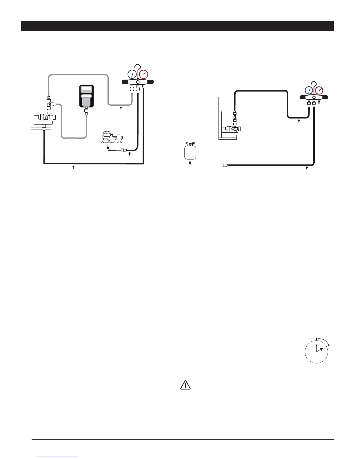
The maximum allowable elevation difference between the de-
humidifier and condensing unit is 30 feet (See FIGURE 8A). If the
elevation difference between the dehumidifier and condensing
unit is greater than 16 feet, an oil trap (as shown above) should be
created in the line set (See FIGURE 8B).
3.4 Brazing the Line Set
WARNING! POLYOL ESTER (POE) OILS USED
WITH HFC-410A REFRIGERANT ABSORB MOISTURE VERY
QUICKLY. IT IS VERY IMPORTANT THAT THE REFRIGERANT
SYSTEM BE KEPT CLOSED AS MUCH AS POSSIBLE. DO NOT
REMOVE LINE SET CAPS OR SERVICE VALVE STUB CAPS UNTIL
YOU ARE READY TO MAKE CONNECTIONS.
WARNING! WHEN USING A HIGH PRESSURE GAS
SUCH AS DRY NITROGEN TO PRESSURIZE A REFRIGERATION
OR AIR CONDITIONING SYSTEM, USE A REGULATOR THAT CAN
CONTROL THE PRESSURE DOWN TO 1 OR 2 PSIG.
CAUTION! BRAZING ALLOYS AND FLUX CON-
TAIN MATERIALS WHICH ARE HAZARDOUS TO YOUR HEALTH.
AVOID BREATHING VAPORS OR FUMES FROM BRAZING
OPERATIONS. PERFORM OPERATIONS ONLY IN WELL-VENTI-
LATED AREAS. WEAR GLOVES AND PROTECTIVE GOGGLES OR
FACE SHIELD TO PROTECT AGAINST BURNS. WASH HANDS
WITH SOAP AND WATER AFTER HANDLING BRAZING ALLOYS
AND FLUX.
IMPORTANT! TO PREVENT STRIPPING OF THE
VARIOUS CAPS USED, THE APPROPRIATELY SIZED WRENCH
SHOULD BE USED AND FITTED SNUGLY OVER THE CAP BEFORE
TIGHTENING.
IMPORTANT! ALLOW BRAZE JOINT TO COOL
BEFORE REMOVING THE WET RAG FROM THE SERVICE VALVE.
TEMPERATURES ABOVE 2500 CAN DAMAGE VALVE SEALS.
IMPORTANT! USE SILVER ALLOY BRAZING
RODS WITH 5% MINIMUM SILVER ALLOY FOR COPPER-TO-
COPPER BRAZING. USE 45% MINIMUM SILVER ALLOY FOR
COPPER-TO-BRASS AND COPPER-TO-STEEL BRAZING.
FOR HVAC INSTALLER ONLY
WARNING! FIRE, EXPLOSION AND PERSONAL SAFETY
HAZARD. FAILURE TO FOLLOW THIS WARNING COULD RESULT IN
DAMAGE, PERSONAL INJURY OR DEATH. NEVER USE OXYGEN TO
PRESSURIZE OR PURGE REFRIGERATION LINES. OXYGEN WHEN
EXPOSED TO A SPARK OR OPEN FLAME, CAN CAUSE FIRE AND/OR AN
EXPLOSION, THAT COULD RESULT IN PROPERTY DAMAGE, PERSONAL
INJURY OR DEATH.
Note – There is a service port inside the dehumidifier (on the gas line)
and both stub tubes of condensing unit. These service ports can be used
to introduce and release nitrogen during brazing.
Use the following procedure to connect the line set to the
Dehumidifier:
CAUTION! THE DEHUMIDIFIER IS SHIPPED FROM THE
FACTORY PRESSURIZED WITH A CHARGE OF INERT GAS AND WITH
RUBBER PLUGS IN THE LINES. PURGE THE INERT GAS FROM THE
DEHUMIDIFIER BY REMOVING THE RUBBER PLUGS IN THE LIQUID
AND GAS LINES TO RELEASE THE INERT GAS BEFORE CONNECTING
THE LINE SET.
Note – If there is no pressure in the dehumidifier when the first plug is
removed, check the dehumidifier for damage and leaks before continu-
ing with the installation.
1. Purge the inert gas from the dehumidifier by removing the rubber
plugs in the liquid and gas lines to release the inert gas before con-
necting the line set.
2. Place a field-provided heat shield, such as a wet rag, against the
dehumidifier and around the piping stubs. The heat shield must be in
place to protect the cabinet from heat damage.
3. Swage the liquid and gas lines (if necessary) to fit onto the dehumidi-
fier lines.
4. Purge the dehumidifier lines and the line set with dry nitrogen (Inert
gas) to prevent oxidation during brazing. Flow dry nitrogen into the
lines at a low pressure of 1 to 2 psig.
5. Braze the line set lines to the dehumidifier lines.
6. Remove the heat shield after brazing and allow the connections to cool.
Use the following procedure to connect the line set to the
Condensing Unit:
1. Cut the line set lines to the proper required length. Deburr the cut
ends of the line set lines.
2. Fit the line stubs with flare fittings (included with the condensing unit)
onto the line set if necessary.
3. Swage the liquid and gas lines (if necessary) to fit onto the line stubs
with the flare fittings.
4. Remove service valve caps and cores.
5. Purge the lines with dry nitrogen (Inert gas) to prevent oxidation dur-
ing brazing.
6. Braze the line set lines to the line stubs.
7. Apply a light coating of refrigeration oil to the flare fitting threads on
the condensing unit valves.
8. Start each flare nut on the corresponding flare fitting on the con-
densing unit valves by hand, making sure the threads are properly
engaged. Tighten the flare nuts hand tight.
30 FT
MAX
CONDENSING
UNIT
OIL TRAP
DEHUMIDIFIER
FIGURE 8B

9Ultra-Aire SD12 Installer’s & Owner’s Manual
FOR HVAC INSTALLER ONLY
9. Carefully torque the flare nuts to the corresponding flare fittings
on the condensing unit valves.
• Torque the liquid line flare nut to 13.3 ft-lbs.
• Torque the suction line flare nut to 30.1 ft-lbs.
10. Reinstall service valve cores and caps.
Note – Alternately, the stubs with the flare fittings can be connected
to the condensing unit before brazing the line set. In this case a field
provided heat shield, such as a wet rag, must be placed over the
flare fittings and valves on the condensing unit to protect them from
heat damage. The service valve cap and core should be removed
before brazing near stub tubes.
3.5 Leak Test Line Set and Dehumidifier
Manifold Gage Set - When checking the system charge, use a
manifold gage set that features low loss anti-blow back fittings.
Manifold gage set used with HFC-410A refrigerant systems must
be capable of handling the higher system operating pressures. The
gages should be rated for use with high side operating pressures
of 0 – 800 psig and low side operating pressures of 30 inches of
vacuum to 250 psig. Dampened gages or anti-flutter gages are
recommended. Gage hoses must be rated for use at up to 800 psig
of pressure with a 4000 psig burst rating.
IMPORTANT! THE ENVIRONMENTAL PROTEC-
TION AGENCY (EPA) PROHIBITS THE INTENTIONAL VENTING OF
HFC REFRIGERANTS DURING MAINTENANCE, SERVICE, REPAIR
AND DISPOSAL OF APPLIANCE. APPROVED METHODS OF
RECOVERY, RECYCLING OR RECLAIMING MUST BE FOLLOWED.
WARNING! WHEN USING A HIGH PRESSURE GAS
SUCH AS DRY NITROGEN TO PRESSURIZE A REFRIGERATION OR
AIR CONDITIONING SYSTEM, USE A REGULATOR THAT CAN CON-
TROL THE PRESSURE DOWN TO 1 OR 2 PSIG.
IMPORTANT! LEAK DETECTOR MUST BE CA-
PABLE OF SENSING HFC REFRIGERANT.
WARNING! REFRIGERANT CAN BE HARMFUL IF
IT IS INHALED. REFRIGERANT MUST BE USED AND RECOVERED
RESPONSIBLY. FAILURE TO FOLLOW THIS WARNING MAY RESULT
IN PERSONAL INJURY OR DEATH.
1. Connect the HFC-410A manifold gage set high pressure hose to
the service port on the suction gas line.
Note – Connecting the high pressure hose to the service port on
the gas line will protect the manifold gage set from high pressure
damage during leak testing. Cap liquid line service port.
2. Make sure all of the valves on the manifold gage set are closed.
Connect a cylinder of HFC-410A refrigerant to the center port of
the manifold gage set.
3. Position the HFC410A refrigerant cylinder to deliver vapor only.
Open the valve on the HFC-410A refrigerant cylinder.
4. Open the high pressure side of the manifold gage set to allow
HFC-410A into the line set and dehumidifier. Weigh in a trace
amount of HFC-410A [A trace amount is a maximum of two
ounces (57g) of refrigerant or 3 PSI]. Close the valve on the
HFC-410A cylinder and the valve on the high pressure side of the
manifold gage set.
5. Disconnect the HFC-410A refrigerant cylinder from the manifold
gage set.
6. Connect a cylinder of dry nitrogen with a pressure regulating
valve to the center port of the manifold gage set.
7. Adjust the dry nitrogen pressure regulator to 150 psig. Open the
valve on the high pressure side of the manifold gage set to
pressurize the line set and dehumidifier.
8. Close the valve on the dry nitrogen cylinder. Close the valve on
the high pressure side of the manifold gage set.
9. Allow the system to rest for a few minutes.
10. Check all (brazed and threaded) joints for leaks using a leak
detector designed to sense HFC refrigerants.
11. After leak testing is complete, disconnect the dry nitrogen cylin-
der from the center port of the manifold gage set and discon-
nect the high pressure hose of the manifold gage set from the
suction gas line service port.
LOW HIGH
MANIFOLD GAUGE SET
NITROGEN
HFC-410A
TO VAPOR
SERVICE VALVE
OUTDOOR UNIT
3-WAY VALVE 2-WAY VALVE
LIQUID LINE STUB
GAS LINE STUB
SERVICE VALVE CAPS
VALVE ROD CAPS
VALVE STEMS
FIGURE 9
FIGURE 10: LEAK CHECK

Ultra-Aire SD12 Installer’s & Owner’s Manual
10
3.6 Evacuating the Line Set and The
Dehumidifier
1. Remove the valve cores from the service ports on the liquid and
gas line stubs using no-loss valve core removal tools.
2. Connect a 1/4” SAE in-line tee to the gas line stub valve core
removal tool.
3. Connect the low pressure side of the manifold gage set to one
of the ports on the 1/4” SAE in-line tee.
4. Connect a micron gage to the remaining port of the 1/4” SAE
in-line tee.
5. Connect the high pressure side of the manifold gage set to the
liquid line stub service port.
6. Connect a vacuum pump to the center port on the manifold
gage set.
7. Open the valve core removal tool valves.
8. Open the high and low pressure sides of the manifold gage set
and start the vacuum pump.
9. After evacuating for a few minutes, close the high and low pres-
sure sides of the manifold gage set and observe the behavior of
the micron gage. A rapid rise in the micron gage reading (pressure)
indicates a leak in the system. If this occurs, check the manifold
gage set, hoses, tee, and valve core removal tools for leaks. If no
leak is found, repeat the leak test procedure in Section 3.5.
10. Evacuate the line set and dehumidifier for a minimum of
15 minutes and check that the micron gauge reads below
500 microns.
11. Close the low and high pressure sides of the manifold gage
set and stop the vacuum pump.
12. Wait 10 minutes.
13. If the micron gage reading rises above 800 microns, check for
leaks and return to step 9.
14. If the micron gage reading remains below 800, close the
valves on the valve core removal tools.
15. Remove the tee from the gas line stub valve core removal tool.
Connect the low pressure side of the manifold gage set to the gas
line stub valve core removal tool.
16. Install the valve core into the liquid line stub service port.
17. Remove the vacuum pump from the center port of the manifold
gage set and proceed to the next section to charge the system.
FOR HVAC INSTALLER ONLY
3.7 Charging the System
The condensing unit is pre-charged with 42 oz. of HFC-410A
refrigerant. The installer will add HFC-410A refrigerant for the
dehumidifier and line set.
1. Calculate the amount of HFC-410A required by determining the
length of the line set and performing the calculation below:
i. 11oz + 2.2oz per every 10 feet of line set length = Total charge
required
2. Connect a cylinder of HFC-410A refrigerant to the center port of the
manifold gage set. Position the HFC410A refrigerant cylinder to deliver
liquid only.
3. Open the valve on the HFC-410A cylinder.
4. Place the HFC-410A cylinder on a refrigerant scale and zero the
scale.
5. Open the valve on the gas line stub valve core removal tool.
6. Open the low pressure side of the manifold gage set and weigh in
the amount of HFC-410A calculated in step 1.
7. Close the valve on the HFC-410A cylinder and the low pressure side
of the manifold gage set.
8. Close the valve on the gas line stub valve core removal tool.
9. Remove the high and low pressure sides of the manifold gage set
from the valve core removal tools.
10. Install the valve core in the gas line stub port using the no-loss
valve core removal tool
11. Remove the no-loss valve core removal tools from the service ports
on the liquid and gas line stubs.
12. Install the caps on the service ports of the liquid
and gas line stubs finger tight, then tighten an additional
1/6 turn. Check the service port caps for leakage –
reinstall if necessary.
3.8 Condensate Water Removal
IMPORTANT! – AUXILIARY DRAIN PAN - WHEN
THE DEHUMIDIFIER IS LOCATED ABOVE A FINISHED SPACE WHERE
DAMAGE MAY RESULT FROM CONDENSATE OVERFLOW, AN AD-
DITIONAL DRAIN PAN WITH AN AUXILIARY DRAIN LINE OF ¾”
MINIMUM DIAMETER MUST BE INSTALLED.
12 111
10
9
8
765
4
3
2
12 111
10
9
8
765
4
3
2
1/6 turn
1/12 turn
OUTDOOR
UNIT
TO VAPOR
SERVICE VALVE
MANIFOLD
GAUGE SET
RECOMMEND
MINIMUM 3/8” HOSE
LOW HIGH
HFC-410A
LOW HIGH
VACUUM PUMP
MANIFOLD
GAUGE SET
MICRON
GAUGE
TO VAPOR
SERVICE VALVE
OUTDOOR
UNIT
RECOMMEND
MINIMUM 3/8” HOSE
500
TO LIQUID SERVICE VALVE
FIGURE 11: EVACUATION
FIGURE 12: CHARGING

11 Ultra-Aire SD12 Installer’s & Owner’s Manual
FOR HVAC INSTALLER ONLY
Note – Check the drain hole in the dehumidifier to verify the opening
and that it is free of any debris before installing the drain line.
Condensate drains by gravity via the dehumidifier drain port. Often
the Ultra-Aire SD12 can be connected to the existing air handler
drain. Use a 3/4” male NPT PVC pipe or adapter to connect to the
drain port. Route drain pipe to an approved drain. Install a trap in the
drain line as shown below. Use an adjustable wrench to secure the
NPT fitting to the drain port. The drain pipe should slope towards the
drain at least 1 inch for every 10 feet of run.
When installing the drain hose, make sure the dehumidifier feet are
extended to raise the dehumidifier 2 1/2” above the ground. Coil the
drain hose under itself or position a spacer to lift the hose 1” off the
ground after the hose has touched the ground. This procedure will
create a trap that ensures your dehumidifier drains correctly. Keep
the hose as flat to the floor as possible. Excessive humps or kinks
will prevent proper drainage.
An optional condensate pump kit may be installed if a lift is re-
quired to dispose of the condensate. The condensate pump kit can
be ordered directly from the factory. See the optional parts list for
information on the kit.
3.9 Ducting
3.9A Installing Duct Collars
The Ultra-Aire SD12 is equipped with 10” and 6” round inlet collars
and a 10” round (ovaled) exhaust collar. Follow instructions included
with collars.
3.9B Ducting for Dehumidification
For the ideal installation, draw air from the central part of the home
and return it to the isolated areas of the home like the bedrooms,
den, utility room, or family room. The ductwork of the existing HVAC
system can be used to supply air to the home. If the existing supply
goes to isolated areas of the home, discharge the supply of the
Ultra-Aire SD12 into the supply of the existing HVAC system. If the
existing heating system incorporates a central supply, installation
of a separate supply duct from the Ultra-Aire SD12 to each isolated
area is recommended. DO NOT draw air directly from the kitchen,
laundry, or isolated basement. You may draw air from a basement
that is open to the home. All flexible ducting connected to the Ultra-
Aire SD12 should be UL listed.
The inlet of the Ultra-Aire SD12 is the 10” diameter hole in the filter
enclosure of the unit. A 10” round collar is supplied with the unit to
attach to round duct. The duct may be permanently attached to the
collar. A 6” round collar is provided with the unit to attach to the 6”
hole in the filter enclosure. The 6” collar should be capped if fresh
make-up air is not desired. If fresh make-up air is desired, see Sec-
tion 3.9C.
A 10” round (ovaled) collar is supplied with the unit for the outlet of
the Ultra-Aire SD12.
A length of flexible ducting on all Ultra-Aire SD12 duct connections
is recommended to reduce noise and vibration transmitted to rigid
ductwork in the structure.
Ducting the Ultra-Aire SD12 as mentioned in Sections 3.9A-3.9G
requires consideration of the following points:
Duct Sizing: For total duct lengths up to 25’, use a minimum 10”
diameter round or equivalent rectangular. For longer lengths, use a
minimum 12” diameter or equivalent. Grills or diffusers on the duct
ends must not excessively restrict airflow.
Isolated Areas: Effective dehumidification may require that ducting
be branched to isolated, stagnant areas. Use 8” or larger diameter
branch ducting to each of two or three areas, use 6” or larger to
each of four or more areas.
Connecting to existing HVAC systems: An optional 10” check
damper is available from the factory to prevent reverse flow through
the Ultra-Aire SD12. If the Ultra-Aire SD12 is ducted to the sup-
ply ducting of the HVAC system, it is recommended that the check
damper be placed in the Ultra-Aire SD12 supply duct. Contact the
factory when connecting to a static pressure of greater than or equal
to +.5” WG.
VENT MUST EXTEND ABOVE THE HEIGHT
OF THE DRAIN BY 2 INCHES.
TRAP MUST BE DEEP ENOUGH TO
OFFSET MAXIMUM STATIC DIFFERENCE
(GENERALLY, 2 INCHES).
DRAIN LINE SHOULD SLOPE A
MINIMUM 1 INCH PER 10 FEET
TO APPROVED DRAIN
DEHUMIDIFIER
VENT
FIGURE 13A: HARD PIPE DRAIN
FIGURE 13B: FLEXIBLE PIPE DRAIN

Ultra-Aire SD12 Installer’s & Owner’s Manual
12
3.9C Ducting for Fresh Air
Fresh air can be brought into the structure by connecting an
insulated duct from outside to the 6” Ultra-Aire SD12 inlet and by
turning on the fan switch or activating the humidity control (on units
with the humidity control panel). Activate the ventilation timer on
the remote control to bring in fresh air. Refer to Section 7.8B for
programming instructions for the ventilation timer. Advantages of
this form of ventilation include:
1. Outside air is filtered before entering the building.
2. Outside air will be dehumidified and cooled before entering if the
Ultra-Aire SD12 is running in dehumidification mode.
3. Drawing air from outside and blowing inside aids in slightly pres-
surizing the structure. This helps prevent dirty and humid air from
entering elsewhere. It also reduces the potential for carcinogenic
radon gas to enter and provides make-up air for open combus-
tion and exhaust devices like the clothes drier, fireplace, and
water heater.
4. Adequate exhaust fans are recommended in the bath rooms and
kitchen.
In cold climates or areas where the outdoor dew point is low at
times, ventilation can be used to dehumidify the structure. This
is accomplished by bringing the dry, low dew point air into the
structure during these times. This approach is often more economi-
cal than running the dehumidifier to remove excess moisture from
the structure. In cold climates, it is critical to adequately ventilate to
reduce the inside moisture content to avoid moisture accumulating
in the wall cavities. For example; in a house that experiences con-
densation on the interior surface of the windows during the winter,
increasing the amount of ventilation will often cure the problem.
An insulated 6” diameter duct is generally sufficient to provide up
to 100 CFM of outside air. Large quantities of outside air will either
positively or negatively impact the performance of the Ultra-Aire
SD12, depending upon inside and outside air conditions. Consult
the factory by calling 1-800-533-7533 for recommendations re-
garding the use of higher flows with your specific application.
The outside air duct should be connected to the 6” round collar
on the filter enclosure of the unit. The 6” round collar includes a
manual damper. Adjust the manual damper to provide the desired
amount of fresh air for ventilation. The amount of fresh air should
be based on the size and occupancy of the residence. If you are
unsure of your ventilation air requirements, consult the factory by
calling 1-800-533-7533 for assistance or check your local building
codes.
3.9D Installation in a Basement or Crawlspace with an
Existing Forced Air HVAC System
It is recommended that a new, separate return duct be installed
FOR HVAC INSTALLER ONLY
for the Ultra-Aire SD12 from a central area of the house. If this is not
possible, and if the existing system has multiple returns, select one
to disconnect from the existing forced air system and use it for the
dedicated Ultra-Aire SD12 return. Always select a return from a central
location in the structure in an area that is always open to the rest of
the structure. Do not use a return from a room that may have its door
closed much of the time.
If the structure in which the Ultra-Aire SD12 is to be installed has an ex-
isting forced air HVAC system, utilize the HVAC system ducting to make
the Ultra-Aire SD12 installation easier.
Basement Installation: Install a separate 10” return for the Ultra-Aire
SD12 in a central area of the structure. Duct the supply of the Ultra-Aire
SD12 to an optional 10” x 10” x 10” tee/damper that is 20% open to the
basement. This allows the dehumidifier to discharge a variable amount
of dehumidified air into a basement that may not be well served by the
existing duct system. Duct the other side of the tee to the air supply of
the existing HVAC system. A backdraft damper is required in the duct
between the 10” tee and the central supply duct to prevent air from be-
ing discharged into the basement during central fan operation. Connect
a duct from outside to the 6” collar of the Ultra-Aire SD12 if you wish to
provide fresh air ventilation.
Crawl Space Installation: Install a separate return for the Ultra-Aire
SD12 in a central area of the structure. Duct the supply of the Ultra-
Aire SD12 to a 10” x 10” x 10” tee/damper that is 20% open to the
crawl space if desired. Duct the other side of the tee to the air supply
of the existing HVAC system ventilation. Connect an insulated duct from
outside to the 6” collar of the Ultra-Aire SD12 if you wish to provide
optional fresh air.
FIGURE 14A: DEHUMIDIFIER BASEMENT INSTALL

13 Ultra-Aire SD12 Installer’s & Owner’s Manual
3.9E Installation in an Attic with an Existing Forced Air
HVAC System
Always install a catch pan with a drain and/or float interrupt switch for
condensate under the Ultra-Aire SD12 in an attic to reduce likelihood of
water damage.
Locate a separate return for the Ultra-Aire SD12 in a central area of
the structure. Duct the supply of the Ultra-Aire SD12 to the air supply
of the existing HVAC system. Connect an insulated duct from outside
to the 6” collar of the Ultra-Aire SD12 if you wish to provide fresh air
ventilation. Adjust damper in the collar to provide the desired amount
of fresh air. Using a remote control, program the unit to bring in the
desired amount of fresh air.
3.9F Installation in a Structure with Two Forced Air HVAC
Systems
The Ultra-Aire SD12 can be installed into two typical HVAC ducting
systems. Install a separate return for the Ultra-Aire SD12 as directed
above. Discharge air from the dehumidifier should be split and routed
to each supply ducting system. A balancing damper and a backdraft
damper is required in each duct between the Ultra-Aire SD12 and the
HVAC ducting system. This allows airflow to be adjusted and prevents
flow of air between the ducting systems. Contact the factory for as-
sistance, if necessary.
IMPORTANT! INSULATED SUPPLY AND RETURN
DUCTS MUST BE USED WHEN INSTALLING THE ULTRA-AIRE SD12
DEHUMIDIFIER IN UNCONDITIONED SPACES TO PREVENT WATER
CONDENSATION ON THE DUCTING. THE ULTRA-AIRE SD12 DEHU-
MIDIFIER WILL REDUCE THE SUPPLY AIR TEMPERATURE 5°F TO
10°F BELOW THE RETURN AIR TEMPERATURE AND PROPERLY
FOR HVAC INSTALLER ONLY
INSULATING THE SUPPLY DUCT IS NECESSARY.
3.9G Installation in a Structure with No Existing Forced
Air HVAC System
When installing the Ultra-Aire SD12 in a structure that does not have
a forced air HVAC system, a single return for the Ultra-Aire SD12
should be installed in central open area of the structure. DO NOT
locate the return in a bathroom or a kitchen. The supply of the
Ultra-Aire SD12 should be located in the remote areas of the struc-
ture (such as bedrooms, den, etc.). By ducting this way, the air inside
the structure will circulate through the Ultra-Aire SD12 to be filtered
and dehumidified. Avoid discharging all the air from the dehumidifier
in one location to prevent overcooling that area. 4” diameter duct
is recommended for branches to the bedrooms, 6” diameter duct is
recommended for branches to larger areas. Refer to section 3.9B for
branch duct sizing.
Connect an insulated duct from outside to the 6” collar of the
Ultra-Aire SD12 if you wish to provide fresh air ventilation.
3.10 Quiet Installation
Consider fan vibration and airflow noise during installation. Use of flex
duct and/or vibration isolation materials during mounting and ducting
will result in quieter operation.
A length of flexible ducting on all Ultra-Aire SD12 duct connections is
recommended to reduce noise and vibration transmitted to rigid
ductwork in the structure.
3.11 System Start Up
1. Rotate the condensing unit fan to check for binding.
2. Inspect all factory and field wiring for loose connections.
3. Check the voltage supply at the condensing unit disconnect switch
and make sure it is 120Vac ±10%. If the supply voltage is outside
this range, do not start the system and repair the power supply
circuit.
4. Plug in the dehumidifier and set the remote control to dehumidify.
Close the condensing unit disconnect to start the condensing unit.
5. Recheck the voltage supply at the condensing unit and make sure
it is 120Vac ±10% while the unit is operating.
6. Check the condensing unit and dehumidifier operation.
4. Controls
The Ultra-Aire SD12 can be equipped with various accessories to
enhance its operation. A remote control must be used with the
Ultra-Aire SD12 system. Therma-Stor offers the DEH 3000 proprietary
controller. The DEH 3000 allows homeowners the ability to moni-
tor and control relative humidity levels in their home. This control is
also offered with a remote sensing option. Refer to Section 3.2B for
Control Installation.
Indoor
Air Supply
UA Indoor
Air Return
UA Supply
Backdraft
Damper
Secondary Drip Pan
Motorized
Damper
DEH 3000
Digital Control
Power Supply
120VAC
Heating & A/C Unit
Fresh Air
Intake
(optional)
Indoor Air
Return
Outdoor
Condensing
Unit
FIGURE 14B: DEHUMIDIFIER ATTIC INSTALL

Ultra-Aire SD12 Installer’s & Owner’s Manual
14
ATTENTION INSTALLER
Ultra-Aire
Dehumidifier
RED
4201 Lien Rd. Madison, WI 53704 •TOLL-FREE 1-800-533-7533 •www.thermastor.com •sales@thermastor.com
TS-234, 11/09
WARNING: Allowing yellow wire to contact red or white wire
will DAMAGE the transformer.
Dehumidifier on : Connect yellow and blue wires.
Fan only on : Connect yellow and green wires.
Accessory power : 24volt AC power supply available for HVAC accessories between yellow and
white(and/or red) wire. Red and white wires are common with each other.
FIGURE 15: Ultra-Aire DEH 3000 Dehumidification & Ventilation Control
YELLOW
BLUE
GREEN
WHITE
Internal Connections
OPTIONAL
DAMPER
24 VAC
DMP COMP FAN
(P/N 4028539; with remote: P/N 4028407)

15 Ultra-Aire SD12 Installer’s & Owner’s Manual
5. Optional Dehumidifier & Ventilation
System Controller
When used with Ultra-Aire Whole House Ventilating
Dehumidifiers, the DEH 3000/3000R allows homeowners the
ability to monitor and control relative humidity levels in their
home.
DEH3000 P/N: 4028539
DEH3000R (remote) P/N: 4028407
Model: DEH 3000
DEH 3000R (remote)
Operating Voltage: 24 VAC
Max Current
DMP, COMP, FAN: 1 AMP each
Humidity Range/Accuracy: 10 – 95% RH,
±
5%
Humidity Setpoint 35% min – 70% max
Auxillary Relay Capacity: 5 Amps, 24VAC
Temp Range/Accuracy: 30°-90°F,
±
2°F
Size: 4.95"L x 1.06"W x 4.19"H
Major Operations
nDigital control of Relative Humidity (Digital Set-Point)
nFan/Filter Operation
nProgrammable Ventilation Timer
nLarge, easy-to-read backlit LCD display
nEasy interaction with air handler fan (Interlock/Lockout)
nHigh Temperature Cut-Out
nDryout Cycle Timer
nAuto Reboot
nRemote Sensor (DEH 3000R Only)
To order call Therma-Stor
at 1-800-533-7533 or
Contact your local distributor
or HVAC contractor.
DEH 3000, DEH 3000R DEHUMIDIFIER & VENTILATION SYSTEM CONTROLLER
DEH3000/DEH 3000R
DEH3000/DEH 3000
R
Part No. 4028539 Part No. 4028407

Ultra-Aire SD12 Installer’s & Owner’s Manual
16
6. Maintenance
6.1 Standard Air Filter
The Ultra-Aire SD12 is equipped with a pleated cloth air filter. This
filter should be checked every six months. Operating the unit with
a dirty filter will reduce dehumidifier capacity and efficiency and
may cause the compressor to cycle off and on unnecessarily on the
defrost control.
To access the air filter, remove the filter access panel from the end
of the Ultra-Aire SD12. The filter should be readily visible and can
be removed by pulling them straight out of the Ultra-Aire SD12.
The pleated cloth filter can generally be vacuumed clean several
times before needing replacement. DO NOT operate the unit
without the standard filter or with a less effective filter than the
standard filter. The heat exchange coils inside the unit could
become clogged and require disassembly to clean. Filter non-
compliance invalidates the product warranty.
6.2 High Efficiency Air Filter – MERV 14
An optional high efficiency pleated microglass paper filter is
available for the Ultra-Aire SD12. This filter is rated as 90%-
95% efficient by the ASHRAE Dust Spot test method 52-76. The
high efficiency pleated microglass paper filter should be used in
conjunction with the standard filter. The filter housing is a seperate
accessory that must be used with the MERV 14 filter. An additional
MERV 11 pre-filter is sold with the filter housing.
This filter is able to remove allergy causing particles from the
airstream. The high efficiency filter has a much larger surface area
than the standard filter, thus the standard filter may need to be
cleaned or replaced several times before the high efficiency filter
requires replacement. Be careful not to damage the fabric media
when handling the high efficiency pleated paper filter. Do not at-
tempt to clean the high efficiency pleated paper filter. It should be
replaced when it becomes restrictive.
6.3 Impeller Fan
The impeller fan motor is factory lubricated for many years of
normal operation, and no further oiling is required.
6.4 Optional Fresh Air Return
Check and clean the screen on the outdoor fresh air return
seasonally. The screen may become plugged during the seasons
when there are many particles in the outdoor air.
6.5 Condensing Unit Maintenance
The compressor and fan motor inside the condensing unit are
permanently lubricated for many years of normal operation, so
maintenance is not required.
Keep the condensing unit clean and free from debris. Check the
coil and other openings on the condensing unit for debris that will
obstruct airflow. The coil on the condensing unit can be carefully
vacuumed or cleaned with a soft bristle brush if needed. Do not
FOR HVAC INSTALLER ONLY
bend the coil fins while cleaning the coil.
Keep the area around the condensing unit clear to allow the required
airflow. Make sure the base of the condensing unit is at least 1” above
ground level and that the condensing unit is level. Do not direct the
discharge towards the condensing unit when mowing grass.
7. Service
7.1 Warranty
A warranty certificate has been enclosed with this unit; read it before
any repair is initiated. If a warranty repair is required, call the factory
first at 1-800-533-7533 Ext. 8459 for warranty claim authorization and
technical assistance.
7.2 Technical Description
The Ultra-Aire SD12 uses a refrigeration system similar to an air
conditioner’s to remove heat and moisture from incoming air, and add
heat to the air that is discharged (See FIGURE 16).
Hot, high-pressure refrigerant gas is routed from the compressor to
the condenser coil. The refrigerant is cooled and condensed by giving
up its heat to the air that is about to be discharged from the unit. The
refrigerant liquid then passes through a filter/drier and capillary tubing
which causes the refrigerant pressure and temperature to drop. It next
enters the evaporator coil where it absorbs heat from the incoming air
and evaporates. The evaporator operates in a flooded condition, which
means that all the evaporator tubes contain liquid refrigerant during
normal operation. A flooded evaporator should maintain nearly constant
pressure and temperature across the entire coil, from inlet to outlet.
The mixture of gas and liquid refrigerant enter the accumulator after
leaving the evaporator coil. The accumulator prevents any liquid
refrigerant from reaching the compressor. The compressor evacuates
the cool refrigerant gas from the accumulator and compresses it to a
high pressure and temperature to repeat the process.
FIGURE 16: REFRIGERATION SYSTEM

17 Ultra-Aire SD12 Installer’s & Owner’s Manual
7.3 Troubleshooting
To turn the dehumidifier ON, make contact between yellow and blue
wires.
To turn the fan ON, make contact between yellow and green wires.
To power an HVAC accessory, connect the accessory to the white (or
red) wire and the yellow wire.
No fans or compressor running. Dehumidification is being called for.
No fan or ventilation call.
1. Dehumidifier unplugged or no power to outlet.
2. Humidity control set too high.
3. Loose connection in dehumidifier internal or control wiring.
4. Defective control transformer.
Compressor is not running. Condensing unit fan and dehumidifier fan
are running. Dehumidification is being called for.
1. Defective compressor run capacitor (Sec. 7.7).
2. Loose connection in compressor wiring.
3. Defective compressor overload (Sec. 7.7A).
4. Defective compressor (Sec. 7.7).
Compressor and condensing unit fan are not running. Dehumidifier
fan is running. Dehumidification is being called for. No fan or ventila-
tion call.
1. No power to condensing unit.
2. Defrost thermostat open.
3. Low pressure switch open.
4. Defective Cond. Relay.
5. Defective condensing unit fan motor.
6. Defective condensing unit fan motor capacitor.
7. Loose connection in condensing unit internal or control wiring.
Compressor and condensing unit fan cycle on and off. Dehumidifier
fan is running. Dehumidification is being called for. No fan or ventila-
tion call.
1. Low ambient temperature and/or humidity causing unit to cycle
through defrost mode.
2. Dirty air filter(s) or dehumidifier air flow restricted.
3. Defrost thermostat defective (Sec. 7.9).
4. Problem with condensing unit power supply.
5. Loose connection in condensing unit internal or control wiring.
Compressor cycles on and off. Dehumidifier fan and condensing unit
fan are running. Dehumidification is being called for.
1. Defective compressor overload (Sec. 7.7A).
2. Defective compressor (Sec. 7.7).
3. Loose connection in compressor wiring.
Condensing unit fan not running. Compressor cycles on and off.
Dehumidifier fan is running.
1. Defective condensing unit fan motor.
2. Defective condensing unit fan motor capacitor.
FOR HVAC INSTALLER ONLY
3. Loose connection in condensing unit fan wiring.
Dehumidifier fan is not running. Dehumidification or fan or ventilation
is being called for.
1. Dehumidifier unplugged or no power to outlet.
2. Loose connection in dehumidifier fan circuit.
3. Obstruction prevents fan impeller rotation.
4. Defective fan.
5. Defective fan relay.
6. Defective impeller run capacitor.
Low dehumidification capacity (evaporator is frosted continuously).
Dehumidification is being called for
1. Defrost thermostat loose or defective (Sec. 7.9).
2. Low refrigerant charge.
3. Dirty air filter(s) or dehumidifier air flow restricted.
4. Excessively restrictive ducting connected to unit.
5. Low ambient temperature dehumidifier operation.
6. Low humidity dehumidifier operation.
No ventilation. Ventilation is being called for.
1. Loose connection in ventilation control circuit.
2. Loose connection in damper power circuit.
3. Defective fresh air damper.
Dehumidifier removes some water, but not as much as expected.
1. Air temperature and/or humidity have dropped.
2. Humidity meter and/or thermometer used are out of calibration.
3. Unit has entered defrost cycle (Sec. 7.9).
4. Dehumidifier air filter dirty (Sec. 6.1 & 6.2).
5. Defective defrost thermostat (Sec 7.9).
6. Low refrigerant charge (Sec. 7.4).
7. Air leak such as loose cover or ducting leaks.
8. Defective compressor (Sec. 7.7).
9. Restrictive ducting (Sec. 3.8).
10. Optional Condensate Pump Safety Switch open (Sec 7.11).
11. Defective condensing unit fan motor.
12. Defective condensing unit fan motor capacitor.
13. Loose connection in condensing unit power or control wiring.
Unit Test to determine problem:
1. Detach remote control wiring connections from dehumidifier.
2. Connect the yellow and green pigtails from the main unit together;
only the impeller fan should run. Disconnect the wires.
3. Connect the yellow and blue pigtails from the main unit together;
the condensing unit and impeller fan should run.
4. If these tests work, the dehumidifer is working properly. You should
check the remote control and control wiring for problems next.
5. Remove the remote control cover from the remote control base and
detach the field installed control wiring. Remove the remote control
base from the wall and carry the remote control to the dehu-
midifier. Connect the blue, yellow, red, and green wires from the
dehumidifer directly to the corresponding terminals on the remote
control. Leave the white wire disconnected!
6. Turn on the fan switch; the dehumidifier impeller fan should run.
Turn off the fan switch.
7. Turn on the humidity control; the condensing unit and dehumidifier
impeller fan should run.
8. If these tests work, the problem is most likely in the field control

Ultra-Aire SD12 Installer’s & Owner’s Manual
18
wiring.
7.4 Refrigerant Charging
If the refrigerant charge is lost due to service or a leak, a new
charge must be accurately weighed in. If any of the old charge is
left in the system, it must be recovered before weighing in the new
charge. Add 53 oz. of HFC-410A plus 2.2 oz. HFC-410A for every
10 feet of line set length to calculate the total refrigerant charge
required. Refer to Section 3.7 for charging procedure.
WARNING! ELECTRIC SHOCK HAZARD. CAN CAUSE
INJURY OR DEATH. UNIT MUST BE GROUNDED IN ACCORDANCE
WITH NATIONAL AND LOCAL CODES. DISCONNECT ALL REMOTE
ELECTRIC POWER SUPPLIES BEFORE OPENING ACCESS PANEL.
UNIT MAY HAVE MULTIPLE POWER SUPPLIES.
7.5 Dehumidifier Impeller Fan Replacement
The motorized impeller fan is a unitary assembly consisting of the
motor and impeller fan. If defective, the complete assembly must
be replaced. See Figure 18B.
1. Unplug the dehumidifier power cord.
2. Remove the cabinet access panel.
3. Disconnect the wires from the dehumidifier fan run capacitor.
Safely discharge the run capacitor. Measure the capacitance
of the capacitor using a capacitance meter. Check the capaci-
tance measurement against the capacitor marked capacitance.
Replace the capacitor if the measured capacitance is not within
10% of the marked capacitance. If a capacitance meter is not
available, an analog ohmmeter can be used to test the capacitor.
Set the ohmmeter to the Rx1 scale. The capacitor is shorted and
must be replaced if continuity exists across its terminals. If there
is no needle movement with the meter set on the Rx100000
scale, the capacitor is open and must be replaced.
4. Remove the impeller fan support bracket.
5. Disconnect the impeller fan leads inside the electric box.
6. Remove the defective impeller fan from the bracket and replace
with it with a new impeller fan.
7. Reassemble the new impeller fan by reversing the above proce-
dure. Note: be sure that the impeller fan aligns with the inlet ring
inside of the dehumidifier.
7.6 Condensing Unit Fan/Blade Replacement
Perform the following tests if the dehumidifier impeller fan and
compressor run, but the condensing unit fan does not.
1. Disconnect the condensing unit power supply. See FIGURE 18C.
2. Remove the cabinet top panel.
3. Disconnect the wires from the condensing unit fan run capaci-
tor. Safely discharge the run capacitor. Measure the capacitance
of the capacitor using a capacitance meter. Check the capaci-
tance measurement against the capacitor marked capacitance.
Replace the capacitor of the measured capacitance is not within
10% of the marked capacitance. If a capacitance meter is not
available, an analog ohmmeter can be used to test the capacitor.
Set the ohmmeter to the Rx1 scale. The capacitor is shorted and
must be replaced if continuity exists across its terminals. If there
is no needle movement with the meter set on the Rx100000
FOR HVAC INSTALLER ONLY
scale, the capacitor is open and must be replaced.
4. Mark the location of the fan blade on the motor shaft. Remove
the fan blade from the motor shaft and slide it to the front of the
condensing unit.
5. Disconnect the fan leads inside the electric box.
6. Remove the defective fan motor from the bracket.
7. Transfer the mark for the fan blade location to the new fan motor
shaft.
8. Attach the new fan motor to the bracket.
9. Slide the fan blade on to the new motor shaft until it is aligned with
the mark you transferred. Attach the fan blade to the motor shaft.
10. Reconnect the fan leads inside the electric box.
11. Install the cabinet top panel.
12. Reconnect the condensing unit power supply.
7.7 Compressor/Capacitor Replacement
This compressor is equipped with a two terminal external overload and
a run capacitor (See FIGURE 18C).
7.7A Checking Compressor Motor Circuits
Perform the following tests if the dehumidifier impeller fan and
condensing unit fan run but the compressor does not with a call for
dehumidification.
1. Disconnect power from the condensing unit; remove the cabinet top
and the electrical connection cover on the compressor top.
2. Reconnect power to the condensing unit and turn the humidity
control to ON. Check for 110 volts from compressor terminal R to
overload terminal 3 using an AC voltmeter. If voltage is present,
go to step 3. If no voltage, there may be a loose connection in the
compressor circuit. Test each component for continuity. See the
appropriate section if a defect is suspected.
3. Disconnect power from the condensing unit, and then disconnect
the red and brown wires from compressor terminals R & S. Using an
ohmmeter check continuity between the points listed below.
4. Compressor terminals C and S: No continuity indicates an open start
winding. The compressor must be replaced. Normal start winding
resistance is 3 to 7 ohms.
5. Compressor terminals C and R: No continuity indicates an open run
winding. The compressor must be replaced. Normal run winding
resistance is .5 to 2 ohms.
6. Compressor terminal C and overload terminal 1: No continuity indi-
cates a defective overload lead.
7. Overload terminals 1 and 3: If there is no continuity, the overload
may be tripped. Wait 10 minutes and try again. If there is still no
continuity, the overload is defective and must be replaced.
8. Compressor terminal C and compressor case: Continuity indicates a
grounded motor. The compressor must be replaced.
9. Disconnect the wires from the compressor run capacitor. Safely
discharge the run capacitor. Measure the capacitance of the capaci-
tor using a capacitance meter. Check the capacitance measurement
against the capacitor marked capacitance. Replace the capacitor of
the measured capacitance is not within 10% of the marked capaci-
tance. If a capacitance meter is not available, an analog ohmmeter

19 Ultra-Aire SD12 Installer’s & Owner’s Manual
FOR HVAC INSTALLER ONLY
can be used to test the capacitor. Set the ohmmeter to the Rx1 scale.
The capacitor is shorted and must be replaced if continuity exists
across its terminals. If there is no needle movement with the meter set
on the Rx100000 scale, the capacitor is open and must be replaced.
10. Reconnect the wires to the compressor and capacitor. Plug in and
turn on the unit. If the compressor fails to start, replace the run
capacitor.
7.7B Replacing a Burned Out Compressor
WARNING! IMPROPER INSTALLATION, ADJUSTMENT, AL-
TERATION, SERVICE OR MAINTENANCE CAN CAUSE PERSONAL INJURY,
LOSS OF LIFE, OR DAMAGE TO PROPERTY.
IMPORTANT! THE CLEAN AIR ACT OF 1990 BANS THE
INTENTIONAL VENTING OF REFRIGERANT (CFCs, HCFCs, AND HFCs)
AS OF JULY1, 1992. APPROVED METHODS OF RECOVERY, RECYCLING
OR RECLAIMING MUST BE FOLLOWED. FINES AND/OR INCARCERATION
MAY BE LEVIED FOR NONCOMPLIANCE.
The refrigerant and oil mixture in a compressor is chemically very stable
under normal operating conditions. However, when an electrical short oc-
curs in the compressor motor, the resulting high temperature arc causes
a portion of the refrigerant oil mixture to break down into carbonaceous
sludge, a very corrosive acid, and water. These contaminants must be
carefully removed otherwise even small residues will attack replacement
compressor motors and cause failures.
The following procedure is effective only if the system is monitored after
replacing the compressor to insure that the clean up was complete.
1. This procedure assumes that the previously listed compressor motor
circuit tests revealed a shorted or open winding.
2. Remove and properly dispose of the system charge. DO NOT vent the
refrigerant or allow it to contact your eyes or skin.
3. Remove the burned out compressor. Use rubber gloves if there is any
possibility of contacting the oil or sludge.
4. To facilitate subsequent steps, determine the type of burn out that
occurred. If the discharge line shows no evidence of sludge and the
suction line is also clean or perhaps has some light carbon deposits,
the burn out occurred while the compressor was not rotating. Con-
taminants are therefore largely confined to the compressor housing.
A single installation of liquid and suction line filter/driers will probably
clean up the system.
If sludge is evident in the discharge line, it will likely be found in the
suction line. This indicates the compressor burned out while running.
Sludge and acid have been pumped throughout the system. Several
changes of the liquid and suction filter/driers may be necessary to
cleanse the system.
5. Correct the system fault that caused the burn out. Consult the factory
for advice.
6. Install the replacement compressor with a new capacitor and an over-
sized liquid line filter.
In a running burn out, install an oversized suction line filter/drier be-
tween the accumulator and compressor. Thoroughly flush the accumu-
lator with refrigerant to remove all trapped sludge and to prevent
the oil hole from becoming plugged. A standing burn out does not
require a suction line filter/drier.
7. Evacuate the system with a good vacuum pump and accurate
vacuum gauge. Leave the pump on the system for at least an hour.
Once the evacuation is complete charge the system per section 7.4.
8. Operate the system for a short period of time, monitoring the suc-
tion pressure to determine that the suction filter is not becoming
plugged. Replace the suction filter/drier if pressure drop occurs. If
a severe running burn out has occurred, several filter/driers may
have to be replaced to remove all of the acid and moisture.
NOTE: NEVER use the compressor to evacuate the system or any part
of it.
7.7C Replacing a Compressor, Nonburn Out
Remove the refrigerant from the system. Replace the compressor
and liquid line filter/drier. Refer to Section 3.5 to check for leaks.
Remove the charge and charge the system per section 7.4. Operate
the system to verify performance.
7.8 Remote Controls
The Ultra-Aire SD12 is controlled by a panel that is remote from the
unit. You may or may not have the devices listed below depending on
the model of the remote control panel you purchased. If the Ultra-
Aire SD12 fails to operate as desired, always check the settings of
the controls to insure that they are correct. Check that the controls
are receiving 24Vac from the Ultra-Aire SD12. Check the connections
between the Ultra-Aire SD12, the control panel, and the field control
wiring.
7.8A Humidity Control
The humidity control is an adjustable switch that closes when the
relative humidity of the air in which it is located rises to the screen
set point.
The Ultra-Aire SD12 is equipped with an automatic defrost mecha-
nism. If the Ultra-Aire SD12 operates in conditions that develop frost
on the evaporator, it will sense the frost build-up and automatically
defrost the evaporator. The Ultra-Aire SD12 may not appear to be
operating correctly during the defrost sequence, but once the defrost
sequence is complete, the Ultra-Aire SD12 will resume dehumidify-
ing.
7.8B Programmable Ventilation Timer – DEH3000/3000R
The ventilation timer controls the dehumidifier impeller fan and the
motorized fresh air damper. When the ventilation timer is activated,
the Ultra-Aire SD12 will circulate the indoor air, and bring in fresh
air from outside. The ventilation timer should be set for the required
ventilation of the residence. The home should be ventilated with
fresh air as suggested by applicable codes and standards.
If the Ultra-Aire SD12 fails to ventilate as expected, check that the
time on the timer is correct. Also check the programs on the timer to
be sure that the timer is calling for ventilation at the correct times.

Ultra-Aire SD12 Installer’s & Owner’s Manual
20
7.9 Defrost Thermostat
The defrost thermostat is attached to the refrigerant suction tube
between the accumulator and the compressor. It will automatically
shut the condensing unit off if the low side refrigerant temperature
drops due to excessive frost formation on the evaporator coil. The
dehumidifier impeller fan will continue to run, causing air to flow
through the evaporator coil and melt the ice. When the ice has
melted, the evaporator temperature will rise and the thermostat will
restart the condensing unit.
7.10 Electric Ventilation Damper
The damper will open when ventilation is called for, allowing fresh
air into the structure through the fresh air inlet duct. The electric
ventilation damper will remain closed when ventilation is not
activated in order to prevent over-ventilating the structure when
the unit is dehumidifying or recirculating the indoor air. The electric
ventilation damper operates on 24 Vac from the control circuit. DO
NOT connect high voltage to the damper motor or damage to the
motor will result. DO NOT force the blade of the damper by hand or
damage to the damper motor may result.
The damper opens in one direction only. The damper rotates very
slowly, allow sufficient time for the damper to cycle. The damper
will take approximately 1 minute to cycle from closed to open or
from open to closed.
FOR HVAC INSTALLER ONLY
If the electric ventilation damper fails to operate:
1. Check that the wiring is correct and that voltage is present at the
damper motor.
2. Check for any obstruction inside the damper. If the electric
ventilation damper fails to operate after performing these checks, it
must be replaced.
7.11 Condensate Pump Kit
An optional condensate pump kit is available from the factory for use
with the Ultra-Aire SD12. Condensate is automatically pumped to a
remote location when the water level in the pump’s reservoir rises to
close the float switch.
The pump also contains a safety float switch. The white leads from this
switch extend from beneath the pump cover. This switch should be in-
stalled in series with the field wire that connects the blue (#7) lead from
the Ultra-Aire SD12 to the dehu terminal on the control panel. Contact a
certified electrician to install the Safety Overflow Switch (optional).
If the pump fails, this switch opens the condensing unit control circuit
and stops water production before the reservoir overflows. The Ultra-Aire
SD12 will continue to ventilate or circulate air as normal, but will not
dehumidify until this switch closes.
LINE NEUTRAL
DEHU.
RELAY
BLOWER
RELAY
BLOWER
XFMR
DEHU.
RELAY
COIL
BLOWER
RELAY
COIL
DEFROST
T-STAT
L. PRESS
SWITCH
RUN
C A P.
1
COMPRESSOR
COND.
RELAY
COND.
RELAY
COIL
115 VAC
LINE NEUTRAL
BLK
RED
BRN
WHT
BLK
BRN
RED
WHT
RUN
C A P.
WHT BLK
BLK
3 4 5 6 7
RUN
C A P.
BLOWER
24VAC SIGNAL
FROM DEHU.
NC
NO
YEL-6
BLU-7
GRN-5
PNK-3
WHT-4
RED-1
YEL-2
BLK-9
BLK-8BLKBLK
BLK-3
WHT-5
BLK-2
BLU-2
115V
24V
COM
COM
BRN-3
BLK-1
BLK-1
+24VAC
DEHU
FAN
COM
CUSTOMER
CONTROL
WIRING
BLU
YEL
GRN
RED
BLK
BLK
24VAC TO
COND.
GRN-4
NO
BLK-5VIO-6
2
S
C
R
1
3
FIGURE 17A: DEHUMIDIFIER WIRING DIAGRAM
FIGURE 17B: CONDENSING UNIT
WIRING DIAGRAM
Other manuals for SD12
2
This manual suits for next models
3
Table of contents
Other Ultra-Aire Dehumidifier manuals
Popular Dehumidifier manuals by other brands

Panasonic
Panasonic CD-B1600R operating instructions

Sonnenkonig
Sonnenkonig SECCO 12 W user manual

ecofort
ecofort ecoQ DryAir 20L Complete instruction manual

Zibro
Zibro D116 operating manual

Johnson Controls Unitary Products
Johnson Controls Unitary Products S1-CD065T01 installation instructions

Admiral
Admiral DH-30M1FC use and care manual