6Ultra-Aire 98H Installation Instructions www.Ultra-Aire.com | (800) 533-7533
Important Precautions
• The device is designed to be installed indoors in a space that is protected from rain and flooding.
• Install the unit with enough space to access one of the side panels for maintenance and service.
• Avoid directing the discharge air at people. The dehumidifier should be used in the upright position.
• If used near a water source, be certain there is no chance the unit could fall into the water or get splashed and
that it is plugged into a dedicated circuit and Ground Fault Circuit Interrupter (GFCI) protected outlet.
• DO NOT use the dehumidifier as a bench or table.
• DO NOT place the dehumidifier directly on structural building members without vibration absorbers or unwanted
noise may result. Place the Ultra-Aire 98H on supports to raise the base of the unit.
• A drain pan with a float switch MUST be placed under the dehumidifier if installed above a living area or above
an area where water leakage could cause damage.
Location Considerations
• Allow sufficient clearance to handle the unit’s overall dimensions as well as the necessary return and supply
ductwork to the unit.
• Allow sufficient clearance for filter removal and to prevent airflow obstruction.
• Electrical service access will require the removal of a side panel. Allow sufficient clearance on a side of the unit.
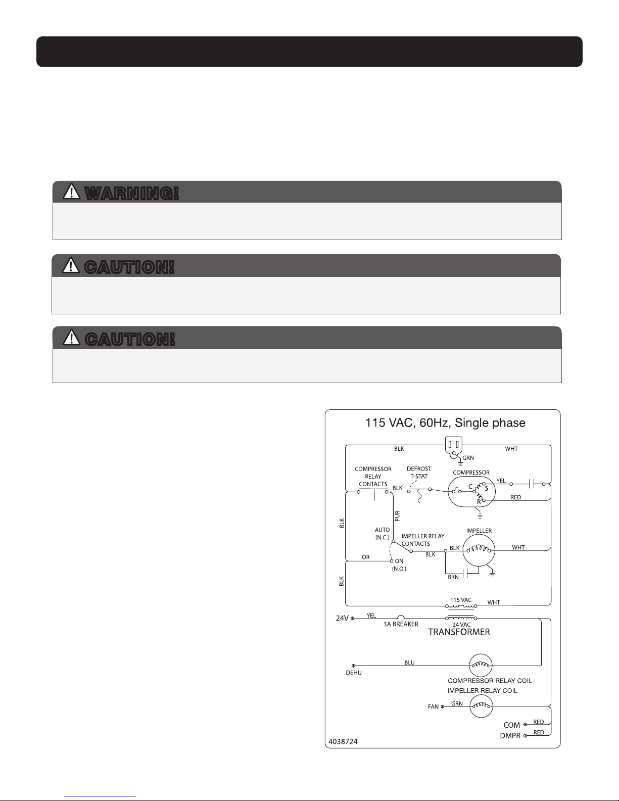
• Locate the dehumidifier in an area where the cord’s length (9') easily reaches a 115 VAC electrical outlet with a
minimum of a 15 Amp circuit capacity.
• Locate the dehumidifier in an area
where field wiring the control (low
voltage) to the unit will be possible.
• It is recommended that a backdraft
damper be used in the discharge duct
of the Ultra-Aire 98H, especially
when connecting to the supply ducting
system. The backdraft damper prevents
supply air from counter flowing through
the Ultra-Aire 98H when it is not
operating. The dehumidifier’s location
should be chosen to allow installation
of this accessory if necessary.
• The Ultra-Aire 98H may be suspended
from structural members with steel
hanger straps or a suitable
alternative, ensuring the assembly
supports the dehumidifier’s base in
its entirety. DO NOT hang the
Ultra-Aire 98H from its cabinet.
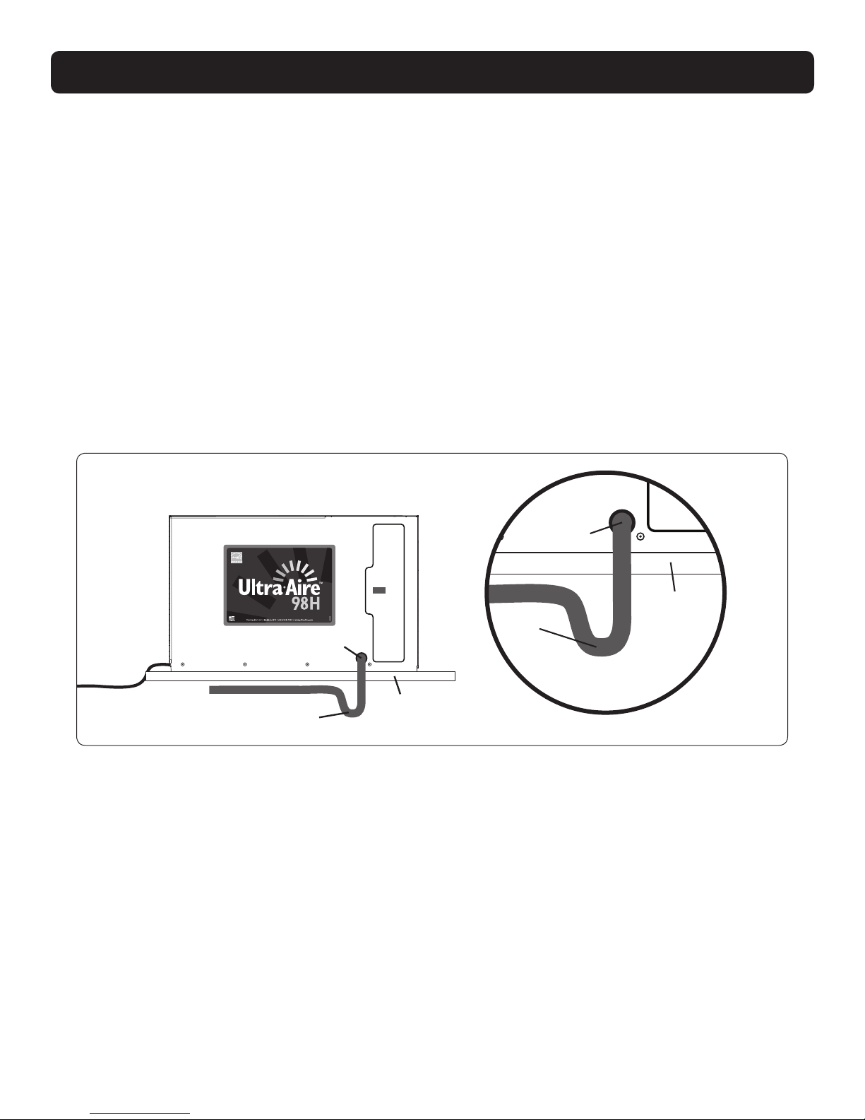
• Allow for proper routing and drainage
of needed drain pipes.
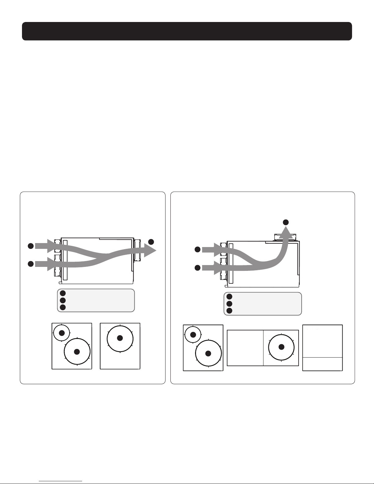
Electrical Service Access
(Either Side)
Filter 9' Power Cord
Top View
Minimum
Clearance
For Filter
(Either Side)
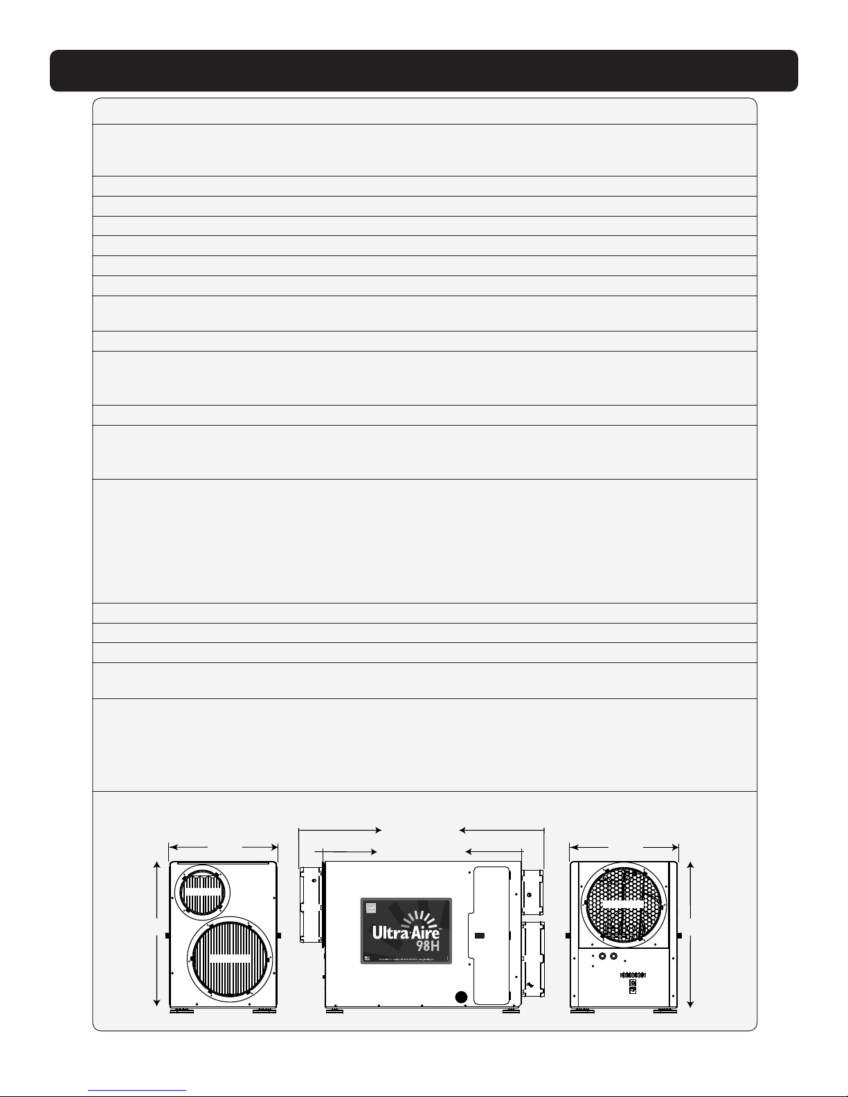
15"
6" Fresh Air Intake (Optional)
10" Return Air Duct
10" Supply Air Duct
A
B
C
32 3/8"
With Collars Installed
26"
Without Collars Installed
B
C
Drain Port
A
DEHUMIDIFIER SET UP