ULTRASUN Q6-0 User manual


•Read the instructions before using this product or consult the attendant for
further information.
•The power supply must be fused with a time-lag fuse.
•The supply voltage (V) and frequency (Hz) must agree with the information given on the
machine type plate. A copy is on the backside of this manual.
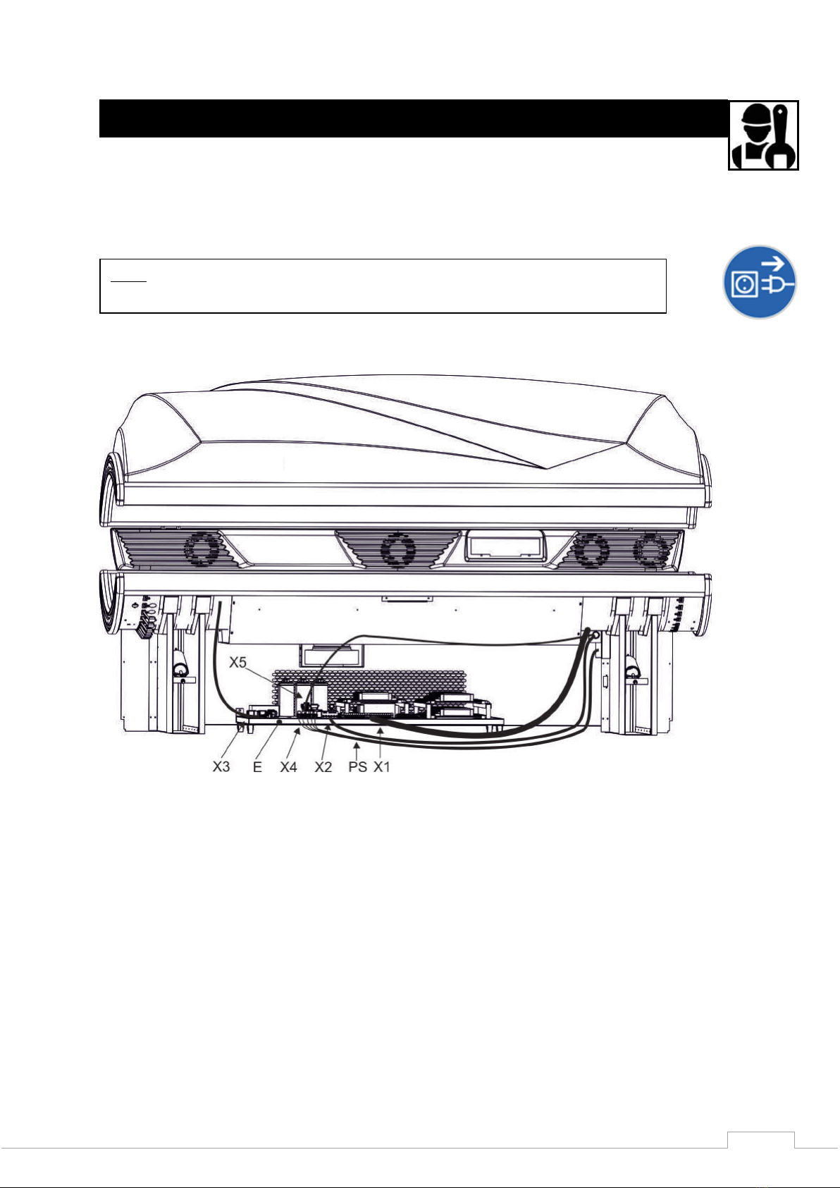
•Before servicing this equipment or changing lamps, remove the power supply cord or
isolate from main supply.
•This equipment must have an earth connection.
•Never use this machine when the timer is faulty.
•Do not use this machine when the airhose is not connected.
•Never use this machine when one of the filters of the facial(s) is broken or removed. You
must check this before use. When during use one of the filter(s) breaks, stop this machine
immediately. A bluefilter is broken when some white light appears through the ‘blue’ light.
It is possible this is weak white light, but it can also be clear white light.
•This device is intended to be used by one person at a time!
•Make sure there is at least 10 cm / 5 inches space between the machine and the
walls/ceilings to ensure proper ventilation.
•Never use this device, if one or all of the acrylics are broken or removed. Check this for each
tanning session.
•This machine may not be operated if the temperature inside the tanning cabin is 30oC /
86 o F or higher.
•Always use the protective sunglasses provided!
•In order to keep your Ultrasun machine in compliance with the standard, you have to make
sure to change lamps, components and accessories with original lamps, components and
accessories only. Otherwise guarantee will be taken off as well as any responsibility and
any liability.
•Water and electricity are a dangerous combination. Do not place your Ultrasun in a humid
room or near water facilities like a shower or swimming pool.
•This machine is equipped with an automatic security system against overheating. In case
there is insufficient ventilation (because the ventilating shafts of the machine are covered
or the ventilation in the room does not function optimally) the appliance will
automatically switch itself off. When the machine has cooled down, the machine will
automatically switch itself on again. However, you should always examine what the cause
was that the machine switched off!
•The appliance is not to be used by children or people with reduced physical, sensory or
mental capabilities, or lack of experience and knowledge, unless they have been given
supervision or instruction.
•Children should be supervised to ensure that they do not play with the appliance.
•Read also the tanning rules on page 16 and 17!
WARNING : PLEASE READ THIS CAREFULLY

3
WARNING…………..………………………………………………………………………………………………………….………..……
CONTENT……………………………………………………………………………………………………………….………………………
EXPLAINING THE ICONS..............................................…………………………………….………………..…………..
(DIS)ASSEMBLY OF THE Q6…………………………………………………………………………………………………………….
AUDIO (OPTION) …………………………………………………………………………………………………………………………..
VOICE GUIDE, WELLNESS SOUND AND BLUETOOTH (OPTION) ……………………………………………………..
CONNECTING THE REMOTE CONTROL………………………………………………………………………………………….
RGB LED CONTROLLER WITH IR DISTANCE CONTROL………….……………………………………………….........……
EXPOSURE SCHEDULE Q6..…………………………………………………………………............................................
TROUBLESHOOTING………………………………………………………………………………………………………………………
MAINTENANCE……………………………………………………………………………………………………………………………..
CHANGING LAMPS AND FACIAL BULBS…………………………………………………........……………………………….
SERVICE PARTS………………………………………………………………………………………………………………………………
DIMENSIONS………………………………………………………………………………………………………….……………………..
TECHNICAL PRODUCTINFORMATION…………………………………………………………………..…………………………
DECLARATION OF CONFORMITY…………………………………………………………………………..…………………….…
CONTACT INFORMATION AND IDENTIFICATION…………………………………………………..…………………………
You have just chosen for a product from the Ultrasun range. You have made an excellent choice. By
this purchase you have chosen for a product which has been carefully manufactured from high quality
parts which have been tested completely and have been checked fully after manufacturing. We advise
you to carefully read through this user manual so you can use the sunbed safely and with many years
of pleasure.
During the development of our professional sunbeds, the specific desires of our customers have been
taken into account. If you still have questions about or suggestions for our sunbeds, please do not
hesitate to contact us.
Please check if the serial number plate at the back side of this user manual resembles the serial
number plate at the back of the sunbed. Ultrasun spends a lot of time and attention on the
development and improvement of the delivered products. Ultrasun holds the right to make changes
without informing you previously.
We hope you enjoy your purchased sunbed.
The Ultrasun team.
Content
2
3
4
5
12
14
14
15
16
18
18
19
19
21
22
23
24

4
Remove the plug from the wall socket when working on the sunbed.
Make sure that the power supply is removed.
Attention: dangerous electrical voltage.
Have a specialized fitter fix, repair or work on the sunbed
Many parts can be recycled, so keep them separate and do not
dispose of them.
Attention: danger, read the instructions carefully and follow the
directions.
Attention: ultraviolet radiation: always wear eye protection when
exposed to UV light and read the corresponding warning
texts.
This user manual consists of all the possible options which you can have on your Ultrasun Q6. If these
options are not relevant to your sunbed, then you can skip the chapters indicated as “(option)”. The
user manual of your Q6 consists of this user manual and a separate user manual for the IQ Touch
Control. The electrical scheme of this sunbed is delivered separately.
Always choose the user manual that has the grey sunbed identification sticker on the backside. And
always keep this user manual close to the sunbed.
•Check if the packaging is in the original state and report possible damages directly to your
transporter. Especially look for possible dents, cracks or water damage on the outside of the
packaging.
•Get all separate parts out of the packaging. Check directly if all parts are present and undamaged.
•May one of these control checks not suffice these requirements, report this as soon as possible to
your Ultrasun distributor.
Explaining The Icons

5
This sunbed is partially pre-build (Fig. 1). For completing the sunbed, the synthetic covers (Fig. 11:L1
and L2 and Fig. 12:L3) need to be attached to the bed. For easy transportation of the sunbed to its
final location, the sunbed can be disassembled as follows:
Remove the plug (Fig. 1:X1, X2, X3, X4 and X5) from the ballast tray (Fig. 1:E) and unscrew the swivel
plates (Fig. 2:D), which are both attached with two screws (3,9x9,5) to the side of the posts. The
cables of the ballast trays (Fig.1:E) now all lay loose, but the ballast tray is attached to the pallet to
restrain eventual damage during transport: Unscrew the transportation screws from the ballast tray
and hereafter the ballast tray can be taken out of the packaging. It is now possible to lift the total
machine (with minimal 4 people) off the pallet for further disassembly. Hold the machine up only on
its metal parts, the synthetic parts are unsuitable for this.
In Fig.2 arrows point to the screws that need to be unscrewed when disassembling the back plates
(Fig.2: A, B and C). This is only necessary in case both posts need to be disassembled for
transportation purposes. It is not a necessary action!
Fig. 1
Note: Always disconnect the power supply before disassembling and during
assembling.
(Dis)assembly Of The Q6

6
Also disassembling the legs and the spring coil system is not recommended, but it can ease
transportation. In Fig.7 an explanation is given how the spring coil and the gas spring are assembled.
Unscrew the four screws (Fig.2:9) at the backside of the bodycooler (Fig.2 and 3:BC).
Lift the top part of your sunbed up (Fig.4) and push the bodycooler (Fig.3:BC) as far to the front so
the screws (Fig.3:5) become visible, remove them.
Fig. 2
BC
Fig. 3
BC

7
Hereafter, disassemble the control- and display-module of
the IQ Touch Control by rotating the two screws on the front
side 90º to the left. The (UTP) cable which is assembled now
can be disconnected. The frontplate of the bodycooler
(Fig.4:H) can now be disassembled. In case your Q6 has an
audio-system with speakers (option), this can be remained
assembled.
Carefully disassemble the back part of the bodycooler
(Fig.4:F) and hereafter the front part (Fig.4:H). The
bodycooler normally rests on the metal strip (Fig.4:G).
Note: Do not damage the ventilators of the bodycooler
during this action!
Hold the top part in the highest position, so a second person
can unscrew the four nuts
M8x10 (Fig.5a, detail a:1 + b:1).
Fig. 5
Fig. 4

8
Place a piece of cardboard for protection at the aluminium edge of the bed and let the front side of
the top part rest on the cardboard. Unscrew the M8 nut (2) on the left (Fig.5a, detail a + b:2) and
right side (Fig.5a, detail b:2) and remove the bolt M8x90 (Fig.5a, detail a + b:3) from the pivot. The
top part is now independent from the bed and can be laid carefully on the ground. The bed now can
be placed to its final location and the ballast tray (Fig.1:E) can be slide under it.
Now the top part can be assembled and attached as follows:
Lift the top part over the bed and let the front of the top part rest on the bed (remember to put the
cardboard at the bed to avoid damage). Place the insulating rings and distance pieces (Fig. 5a)
between the hinge plates and assemble the bolts M8x90 (Fig. 5a:2) on the left (Fig.5a, detail a) and
right (Fig.5a, detail b) in the pivot.
Hold the top part in the highest position, so a second person can screw the four nuts
M8x10 (Fig. 5a, detail a:1 + b:1). Note that the bolts M8 (Fig.5a:1) have been provided with
the distance pieces!

9
In case the spring coil (Fig.6 and 7:MT) and the
gas springs (Fig.6 and 7:G) are disassembled,
these can now be assembled in their position again.
Turn the single nut on the thread with the ring until it
reaches the end on the backside with the double nut
(Fig.2b:DM). Note that the spring coil must return in
its exact same position as it was before the disassembly.
Figure 7 displays this position.
Assemble the back plates A, B and C like in Fig.2
Carefully slide the backside of the bodycooler (Fig.4:F) around the hinge construction (in the
direction of the arrows) and place the bottom on the steel strip (Fig.4:G) which is attached to the
backside of the bed.
The bodycooler rests on this metal strip. The front plate of the bodycooler (Fig.4:H) can now be
constructed with the screws from Fig.3:5 and on the backside with the screws from Fig.2:9. The
control- and display module of the IQ Touch Control can be assembled and connected with the
network cable.
T
G
MT
MT
Fig.6
DM
G
MT
Fig.7

10
Connect all cables (X1, X2, X3 and X5 from Fig.1) and assemble the swivel plates (Fig.2:D).
Connect the power supply cable (Fig.1:PS) to the power supply X4. This needs to be done like is
indicated in Fig.8 (for 230V)
In the end, the ballast tray (Fig.1:E) needs to be secured with the two already assembled screws in
the left post (Fig.9:P)
Attach the side covers (Fig.11:L1 and L2) on both sides of the bed, by sliding the top of the cover into
the synthetic end profile and placing it over the metal plate on the backside (Fig.12:K).Fasten both
side covers with 3,9x9,5 screws to the metal backside like is indicated (arrows) in Fig.10.
Note: Do not damage the ventilators of the bodycooler during this action!
Fig. 8
3 x 2,5 mm2
Fig. 9

11
At the backside of the sunbed the connection for the universal remote control is located (Fig.11:DC),
in the chapter “connecting the remote control” detailed information about the function of this
connection is mentioned.
Attach the front cover (Fig.11:L3) to the machine, by first placing the top in the ditch of the bed and
hereafter by pushing the lower part of the cover to the inside. Fasten both sides of the front cover
with 3,9x19 screws like is indicated in Fig.11:M. Attach the synthetic decoration strip as a cover
between the aluminium profile and the synthetic front cover (Fig.11:N)
Now all previous actions are completed and checked, the power supply can be connected. The
sunbed is now ready for use. Read the user manual of the IQ Touch Control for instructions how to
control the sunbed. We recommend to disconnect the machine from the power supply in case the
machine will not be used for a long time.
M
L3
Fig. 12
M
Fig. 10
Fig. 11
L1
L2
N
DC

12
If your Q6 is equipped with the audio-option (the Audio Pro option), then you have
Audio* (Option)
Fig. 12
Fig. 13

13
two speakers in the bodycooler (Fig. 12:S) and a subwoofer (bass speaker) which will be placed
separately behind the sunbed (Fig.14:SW). At the side of the bodycooler a connection can be found
with the entrance of the sound (Fig.13:input): this can be an MP3/iPod.
This connection is made with an so-called 3,5 mm (stereo-) plug. Fig. 14 displays schematically how
the wires are connected to the audio part from the IQ Touch Control
The drawing on the next page (Fig.15) show the connections and operating elements of the
bass speaker.
For more information about the audio connections read the included user manual of the IQ
Touch Control.
Fig. 15
Fig. 14
230 V AC ONLY
FOR AUDIO !
NOTE
It is advisable to set the Volume
and the Bass control halfway.
Please note that if you adjust the
Volume and the Bass control to a higher
level there is a possibility that the sound
will be distorted. Eventually this can
lead to damaged speakers.
ATTENTION
Loud music can cause hearing
problems!
3,5 mm MP3/iPod input
USB connection
Fig. 14

14
In case your Q6 is equipped with the Music Pro audio option, the possibility exists to extend this
option by including the Voice Guide, Wellness Sound and/or Bluetooth option. In case one of these
options is installed, this is automatically recognized by the IQ Touch Control and visible in the control
display. Read the user manual of the IQ Touch Control for more information.
At the backside of the sunbed, the connector for the remote control is located. The connections
resemble the figure above.
Note: The only purpose of this connection is for controlling the sunbed by means of a coinbox or a
remote control with a potential free switch or contact.
The counterproductive plug can be connected to your control box, timer or coin box. An incorrect
connection of the connector can lead to damage to the parts of the sunbed.
In case you would like to use a potential free switch or contact, the parameter P021 of the IQ Touch
Control needs to be changed to P021:01 or P021:02 depending upon the application. For this, please
read the user manual of the particular remote control you want to use.
The 220-230V connection is only intended as an exit for connecting the electronics in a remote
control (for example a Paytronic coin box) with a maximal current consumption of 1,0 ampere.
The exit L* delivers 230V in case the machine is turned on. This connection can be used by
applications like feedback signal or occupied signal. Always note that during assembly the plug is
connected in accordance to the manufacturing method (the smooth and ribbed side must be in
accordance with each other).
In case larger distances must be bridged or in case disturbances in the pipes arise, the possibility
exists to place an Opto-box (Ultrasun article number 3T0480) between the remote control pipes.
Voice Guide, Wellness Sound And Bluetooth* (Option)
Connecting The Remote Control
Only for potential free remote control connections

15
Your tanning device is equipped with a RGB led controller and a remote control with which you can
control the colour settings of the Rainbow-led strip. With the led controller (Fig.1:A) you can set the
colour changing, colour jumping, etc. and the colour can be set to static at any time. This system is
applicable for 12V DC. The maximum current per color may not exceed 4 Amp. The electrical scheme
for the led controller can be found in Fig.2
The remote control has 24 buttons, each having its own function:
The 16 “static” buttons give the opportunity for an immediate color selection, the other buttons have
the following functions:
-Brightness up/speed up and Brightness down / speed down : if a static color is
selected, the brightness can be changed to more or less bright. If another button is
selected, the speed can be changed up or down .
-On and Off button : switches your RGB led controller on or off.
-7 color jump (FLASH): gives the opportunity to jump from color to color.
-White fade in/out (STROBE) : gives a strobe effect in white color.
-7 color change (FADE): gives the opportunity to run automatically through the color
spectrum.
-3 color jump (SMOOTH): jumps through the three basic colors red, blue and green.
Fig. 1
Fig. 2
Be aware that the infrared transmitter should be directed to the receiver
RGB Led Controller With IR Distance Control

16
Recommended exposure times for the Q6 – for UV4:
RECOMMENDED EXPOSURE SCHEDULE
MAXIMUM EXPOSURE TIMES (IN
MINUTES)
CLASS
SKIN TYPES
week 1
week 2
week 3
week 4
I
Sensitive skin
Tanning not advised
Burns easily and severly, and does not
tan.
II
Light skin
6
10
15
20
Burns easily and severly, and tans
minimally.
III
Normal skin
7
12
16
20
Burns moderately, and tans
moderately
IV
Dark skin
8
13
17
20
Burns minimally, and tans well or
above agerage.
Allow at least 48 hours between all exposures, tan maintenance: 1-2 times weekly
MAXIMUM EXPOSURE TIME: 20 minutes.
Notice the following tanning rules for proper and safe use of your tanning device :
•The exposure time for first session must not be shorter than 1 minute.
•Follow the recommendations concerning exposure duration and exposure intervals
•Protect your eyes from visible and infrared radiation, take adequate precautions ! Always use
the provided sunglasses!
•Do not sunbath and use the machine on the same day.
•This device is intended to be used by one person at a time!
•Lie on the sunlamp bed and lower the top section to its internally regulated stop point to attain
this position. Any other position may result in overexposure.
•Always use the protective sunglasses provided.
•Remove cosmetics well in advance of exposure and do not apply any sunscreens.
•Do not undergo exposure when taking medicines or using cosmetics, which increase sensitivity to
ultraviolet radiation. If in doubt, take medical advice.
•Follow the recommendations concerning exposure duration and exposure intervals.
•Seek medical advice if persistent lumps, sores or pigmented moles develop on the skin.
•Ultraviolet radiation from the sun or UV-machines can cause injury to skin or eyes. These
biological effects depend upon the quality and the quantity of the radiation as well as the skin
sensitivity of the individual.
•The skin may develop sunburn after an excessive exposure. Excessively repeated exposure to
ultraviolet radiation from the sun or the machine may lead to premature ageing of the skin as
well as increased risk of development of skin tumours.
Exposure Schedule Q6

17
•The unprotected eye may develop surface inflammation, and in some cases, damage may occur
to the retina after excessive exposure. Cataracts may develop after many repeated exposures.
Therefore: always use the protective sunglasses provided.
•This machine is not to be used by people burning without tanning when exposed to the sun, by
people suffering from sunburn, by people suffering from or previously suffering from skin cancer
or predisposed to skin cancer.
•Read this carefully: if unexpected side effects, such as itching, occur within 48 hours of the first
session of using a UV appliance, medical advice should be sought prior to further UV exposure.
•This appliance is not to be used by people burning without tanning when exposed to the sun, by
people suffering from sunburn, by people under the age of 18, or by people suffering from (or
previously suffering from) skin cancer or predisposed to skin cancer.
•Do not undergo exposure when taking medicines or using cosmetics, which increase sensitivity to
ultraviolet radiation. If in doubt, take medical advice.
•This appliance shall not be used by persons under medical care for diseases that involve
photosensitivity or persons receiving photosensitizing medications.
•Seek medical advice if persistent lumps, sores or pigmented moles develop on the skin.
•Ultraviolet radiation from the sun or UV-machines can cause injury to skin or eyes. These
biological effects depend upon the quality and the quantity of the radiation as well as the skin
sensitivity of the individual.
•The unprotected eye may develop surface inflammation, and in some cases, damage may occur
to the retina after excessive exposure. Cataracts may develop after many repeated exposures.
•Read this carefully: if unexpected side effects, such as itching, occur within 48 hours of the first
session of using a UV appliance, medical advice should be sought prior to further UV exposure.
•The skin may develop sunburn after an excessive exposure. Excessively repeated exposure to
ultraviolet radiation from the sun or the machine may lead to premature ageing of the skin as
well as increased risk of development of skin tumours.
•Remove cosmetics well in advance of exposure and do not apply any sunscreens.
•According to basic standards your Ultrasun tanning equipment needs to be equipped with
original parts and lamps. In every other case the guarantee is taken off as well as any
responsibility and any liability.
Many parts can be recycled, so keep them separate and do not dispose
of them.

18
When your sunbed or part of it (top, bed or facial) does not function, please check:
-the fuses/differential switch of your main supply;
-the connection to the main supply and fuse (Fig. 8 and Fig.9).
-the thermal switches (temperature safety), these are checked by the IQ Touch Control, read
the user manual of the IQ Touch Control for more information;
-the (possible) plug connection between the different parts (for example the ballast tray, base,
top or bodycooler, Fig.7:Z1, X2, X3);
-the broken-glass sensors for the facials;
•If one of the lamps does not function anymore, change it with the lamp next to it. If it still does
not work, change the starter;
•If the facial(s) not work, check if the switch is the correct position;
•If the top does not stay in the required positions or it moves up and down by itself, the spring
coils in the compartments B1 and B2 (Fig. 14) need to be adjusted;
•Switch off the power supply to the machine in case of:
-working inside the sunbed;
-fans are out of order;
-any doubt of the nature of the failure;
•Please contact your technical service in case the problem cannot be solved with the above
mentioned possibilities;
After 50 hours or at least after one month and then every 500 hours or 6 months:
•Visual inspection of all parts inside the sunbed;
•Remove dust and fluffs inside;
•Check the working of the whole machine;
•Control screws and nuts (if loose tighten);
•Clean the filters of the facials;
Always:
•Pay attention to strange noises in the sunbed;
•Clean the acrylics after every tanning session;
•Consult an authorised service agent in the event your Ultrasun machine has a failure;
Maintenance
Troubleshooting

19
When effective life of your lamps and facial bulbs is over, or when there is an obvious decrease in the
tanning results, it is necessary to change the lamps and facial bulbs.
The top:
Remove the acrylic by carefully disassembling the synthetic strip on the whole length of the front
side. Now gently lift the acrylic from the top (with minimal two people) by taking the backside out of
the profile. Then the acrylic can be cleaned and the lamps can be changed.
The bed:
Remove the acrylic by disassembling the synthetic strip on the front and back side. Once the strip is
removed, the acrylic can simply be lifted and removed, preferably by two people.
When changing the lamps, turn the lamps in the lamp holders until the ‘click’ before you remove
them. When changing the lamps, also remove the dust from the machine (particularly around the
fans) and clean the acrylics from the inside. Read the assembly instructions for more information.
The facials (only for units with facial tanners):
To change the facial bulb, remove the cover from the top. This is possible by disassembling the two
synthetic profiles and taking the cover off. The reflector with the facial bulb inside can be completely
removed by removing the two screws (on both sides) from the reflector. At the same time the two
wires of the facial bulb must be disconnected. The facial bulb can be removed out of the pinch-spring
and replaced by a new one. Do not touch the glass of the facial bulb with your fingers. Remove the
dust and clean the white and blue filter with a
glass cleaning fluid.
Although this Ultrasun Q6 is equipped with high quality parts, there is a possibility the parts will get
exposed to mechanical erosion. When this happens, these parts need to be replaced. In the table
“Technical product information” the specific article numbers of the lamps and facial burners are
listed. In the separately enclosed electrical scheme the article numbers of the electrical parts are
mentioned in the inscription. In order to keep your Ultrasun Q6 machine in compliance with the
standard, you have to make sure to change lamps, components and accessories with original lamps,
components and accessories only. Otherwise guarantee will be taken off as well as any responsibility
and any liability.
Service: Parts And Registration
Attention:Make sure that the new lamps and facial bulbs are of the same type
as the previous ones!
Attention:When changing lamps, first remove the power supply, then remove
the acrylic.
Changing Lamps And Facial Bulbs

20
Below other parts are listed that can be ordered with their related article number.
Q6
Art. number
Article
2B6205 Bluefilter for facial : MUG6+– 205x270x3 mm
2W0031 Whitefilter for facial UV 4: SunFlex 4 – 205x270x4 mm
2W0020 Whitefilter for facial UV 3: 320 – 205x270x4 mm
2Z0100
UV eye protection sunglasses brown special for IQ Touch Control
5A3510
Acrylic plate for bed: Model Q6 – 4 mm
5A7030
Acrylic plate for top: Model Q6 – 3 mm
5M0012
Acrylic cushion transparent
5R0076
Synthetic profile for acrylic plate or synthetic cover: color silver - 2071 mm
2P0050
Paytronic coin payment system
In order to keep a good overview of failures and ensuing repairs, we suggest you to register all
notifications in the table on this page. Do not register messages that appear on the IQ Touch Control,
these are stored in the timer memory and can be read out in parameter 180.
Enter all information as completely as possible in the table on the next page, so that you keep a good
overview of the history of your Ultrasun Q6.
Date
Failure
Replaced parts
Repaired by
Date
--
--
--
--
--
--
--
--
--
--
--
--
--
--
--
--
--
--
--
--
--
--
--
--
--
--
--
--
--
--
--
--
--
--
--
--
--
--
--
--
Table of contents
Other ULTRASUN Personal Care Product manuals
Popular Personal Care Product manuals by other brands

gk-medizinmechanik
gk-medizinmechanik GK Basic user manual

Orliman
Orliman oneplus OPL354 Use and maintenance instructions

HoMedics
HoMedics StyleSpa TRAVELER MAN-50C Instruction manual and warranty information

Panasonic
Panasonic EH2511 operating instructions

Rio
Rio faceLITE manual

BresoTEC
BresoTEC URU user guide